Available online at www.sciencedirect.com
ScienceDirect Procedia CIRP 61 (2017) 715 – 720
The 24th CIRP Conference on Life Cycle Engineering
Integrating Environmental Impacts with SysML in MBSE methods Sébastien Bougaina*, Detlef Gerharda Technische Universitaet Wien, MIVP Research Group, Getreidemarkt 9, 1060, Vienna, Austria * Corresponding author. Tel.: +43 (1) 58801 - 30757; fax: +43 (1) 58801 - 307 98. E-mail address:
[email protected]
Abstract
The continuously growing integration of mechanics, electronics, and informatics into modern products introduces a considerable complexity into product development activities. Model-Based Systems Engineering (MBSE) methods are one approach to handle this complexity. Eco-design methods, which are also increasingly important due to sustainability focus of many companies, is not fully implemented or even not taken into account at all in MBSE methods. Therefore, this paper aims at integrating the environmental impacts of a mechatronic product in a MBSE method using Systems Modelling Language (SysML). © Authors. Published by Elsevier B.V. This is an open access article under the CC BY-NC-ND license ©2017 2017The The Authors. Published by Elsevier B.V. (http://creativecommons.org/licenses/by-nc-nd/4.0/). Peer-review under responsibility of the scientific committee of the 24th CIRP Conference on Life Cycle Engineering. Peer-review under responsibility of the scientific committee of the 24th CIRP Conference on Life Cycle Engineering Keywords: MBSE; SysML; Environmental impacts; Eco-design.
1. Introduction Products get increasingly complex combining different fields of knowledge like software, mechanics, electrics and electronics. Model-Based Systems Engineering (MBSE) is an interdisciplinary approach for handling complexity during product development. The System Modelling Language (SysML) [1] is the main modelling language incorporating MBSE methods. Meanwhile, since environmental threats are major concerns for consumers and companies, they are getting more attention in the product creation processes. Therefore, consideration of environmental issues along the whole product’s life cycle increases in importance. This additional complexity stemming from environmental aspects is not explicitly integrated in MBSE. For this reason, this paper presents a method that integrates the environmental impacts in MBSE using SysML. The method assists engineers with understanding and modelling the intricacy of major environmental impacts of the product, proposing optimizations and reports. First, the paper gives an overview of related work on Product Lifecycle Management (PLM) and applied modelling of environmental impacts with SysML. In chapter 3, the method itself is detailed with a focus on the following points: consideration of appropriate requirements, modelling of the environmental impact with
SysML and finally reporting and evaluation. Using a 3D Printer as example product, the method is illustrated. SysML models are generated using the software tool MagicDraw [2]. 2. Related work 2.1. Model-Based Systems Engineering and Product Lifecycle Management According to the International Council on System Engineering (INCOSE), “Systems Engineering is an interdisciplinary approach and means to enable the realization of successful systems. It focuses on defining customer needs and required functionality early in the development cycle, documenting requirements, then proceeding with design synthesis and system validation while considering the complete problem” [3]. MBSE is an extension of the systems engineering (SE) approach that focusses on capturing product properties and engineering information consequently within models instead of predominantly using documents. The various representations from the MBSE are Requirements, Function, Logic, Behavior, and Structure. The resulting analysis provides traceability from requirement to component and vice versa.
2212-8271 © 2017 The Authors. Published by Elsevier B.V. This is an open access article under the CC BY-NC-ND license (http://creativecommons.org/licenses/by-nc-nd/4.0/). Peer-review under responsibility of the scientific committee of the 24th CIRP Conference on Life Cycle Engineering doi:10.1016/j.procir.2016.11.196
716
Sébastien Bougain and Detlef Gerhard / Procedia CIRP 61 (2017) 715 – 720
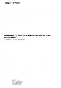
VDI guideline 2206 [4] supports the development of complex mechatronic product on methodic level. Particularly, the so called V-model, see Fig 1, guides through development processes for engineering design of mechatronic products. Although environmental issues are not addressed specifically in the V-model they can be treated along the development.
R: Requirements F: Function L: Logics/Behaviour P: Physical Structure
Figure 1, The V-model, adapted from [4]
Product Lifecycle Management (PLM) is an approach to holistically manage all product related information in engineering design processes and beyond, especially production and usage [5]. PLM is based on the combination of various systems and models along the product’s lifecycle so as to connect them for increasing the traceability between the different abstraction levels. The lifecycle phases that are explicitly treated in eco-design methods are as follows: material extraction, manufacturing, operation and use, end-oflife, and several transport processes within the phases [6].
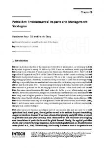
2.2. The System Modelling Language (SysML) and its application for modelling environmental impacts To successfully model function, behavior and other aspects of an intended product, SysML, which is an extension of the Unified Modeling Language (UML), is integrated. Each model is enriched with different relations like “composition”, “aggregation”, “satisfy”, “verify” etc. that state the relationship between the blocks. The goal is to have a clear and fast comprehension of the whole system, see Fig 2. Moreover, the different SysML models are interlinked with one another. For instance, when a product’s part is fulfilling a requirement it can be shown in the requirements diagram with a “satisfies” relationship established between the involved objects. An interesting part of SysML software tools is that they can be linked with a core solver in order to perform calculations. The plugin ParaMagic for MagicDraw from InterCAX [7] for instance is able to extract information from the model and make calculations with a chosen core solver like Mathematica or Simulink. This can help the designer for assessing the product in the early stages of the development and have lots of applications. Concerning interaction between the environment and the product, Matar [8] detailed a SE approach for realizing sustainability in infrastructure projects. One goal of his
research is to “adequately represent, but simplify, the complexities of both the environmental system and the construction product and production systems for both buildings and infrastructure projects.” Thanks to SysML, a model of interaction between the environment and the product (in this case a building) is detailed. This is shown as an interacting model using blocks and showing the exchange of energy, material and information. With the help of such a representation, design engineers are able to assess the impact of each part or function. This could be further used for a complete representation of the environmental interaction as for instance eutrophication or waste water assessments. Concerning manufacturing phase, Romaniw et al propose an equivalent approach using blocks and relations for calculating environmental impacts of a production system using the InterCAX tool [9]. The method uses a slightly different Activity-Based Costing method, where a manufactured part is made via a manufacturing operation which consumes resources. All operations will consume a quantity of energy and produce carbon dioxide. Constraints and relations define for a machine how much energy is consumed and how much is emitted. The InterCAX plugin is then capable of extracting, exploiting and calculating the environmental impacts of a machine and assessing the whole factory. Related work about the use of SysML with calculation of environmental impacts exists but has a different approach as it will be analyzed in chapter 3. 2.3. Eco-design software Wimmer et al [10] developed in the early 2000s the ECODESIGN PILOT (EP), a tool for providing and supporting strategies in order to design a product with consideration about the environment. It was the result of an investigation based on many eco-design projects and optimizations of product in order to deduce a method like in a Case-Based Reasoning (CBR) approach. The software follows an approach of qualitatively enabling design engineers to quickly identify appropriate eco-design measures for the improvement of their product. Most important, design engineers have to determine, in which phase a product consumes and emits the most. This process is supported by the software assistant, which asks for information about the product like materials used, life expectancy, energy used for manufacturing etc. in order to determine the phase in which the product probably consumes the most. Then the software gives different strategies with questions that the designer has to ask himself (and rate from 5 to 10) in order to decrease the environmental impact of the product. Each of these strategies is filled with measures helping the design engineer to apprehend the issue if she or he is not familiar with the subject. For instance, for a use intensive product, the following 5 strategies are proposed in EP, the last is detailed with its 6 measures: x Optimizing product functionality x Improving maintenance x Ensuring environmental safety performance x Reducing consumption at use stage x Avoidance of waste at use stage
Sébastien Bougain and Detlef Gerhard / Procedia CIRP 61 (2017) 715 – 720
Figure 2, the pillars of SysML from [11]
x Closed cycles for process materials needed at use stage x Avoid and/or minimize waste at use stage x Avoid and/or minimize environmental damage caused by emissions, waste, noise, etc. at use stage x Provide for incentives for and possibility of collecting waste from use stage x Reuse and/or recycling of waste from use stage x Ensure environmentally acceptable disposal of waste from use stage Each measure possesses a priority (from 0 to 40) calculated from the level of fulfillment this measure has achieved (0; 1; 2; 3 or 4) multiplied by its relevance (0; 5 or 10). The values are estimated by design engineers. Each measure can then be annotated with ideas for realization, costs, feasibility and action. A critical success factor is to integrate eco-design methods at the beginning of product development. The challenge is that at this stage of the process only little information about the product, the detailed production process and even the usage patterns is available, and therefore, assessment is quite difficult. 3. Method The method shown in this paper has three different goals. First, an adequate eco-design strategy for design engineers to assist in making the right (verified) decisions during product development projects as soon as possible is proposed. Second, this method aims at integrating the environmental impacts (Green House Gas Potential (GHGP) and Cumulative Energy Demand (CED) from four lifecycle phases: Extraction phase, Manufacturing phase, Use phase, and End-of-Life phase. The transport phase is not integrated yet; it will be included in further works. Third, the method is intended to enable
reporting about the product and its sustainability at an early stage. This facilitates the integration of eco-design methods adequately in the product development process and enables design engineers to take appropriate actions and decisions about the product as early as possible. Eigner et al [12] developed a similar approach with an extended V-model for multidisciplinary product development. Their model is adapted from the V-model from the VDI 2206 with extensions about the product’s lifecycle phases. The approach developed in this paper is different and concerns all the life-cycle phases taken into account as early as possible in the V-model and adds a dynamical eco-design strategy. A Mendelmax 3D Printer [13] serves as product development example for this paper. The requirement phase is the stage within the product lifecycle, where the demands to a product are formulated and translated afterwards in a technical point of view. It is the crucial phase for product development as it sets the basis for the whole design. According to the EN NF X-50-100 [14], different requirements diagrams for each use phase are modelled separately. Inside each model, the corresponding eco-design strategies are formulated with a requirement point of view and added by default. Commonly, for mechatronic products like machine tools, cars or airplanes the most energy-intensive phase is the use phase because of fuel or electricity consumption during operation. That is why, as a first assumption, this method uses by default the strategies that have to be implemented for use-intensive product. For the example of the 3D printer, the use phase is also considered as the most intensive in terms of the environmental impact. The requirements derived from EP method are shown in each phase in a separate requirements diagram. Each strategy from a lifecycle phase has a title and an importance (from 0 to 2). The importance of a strategy is characterized with a value
717
718
Sébastien Bougain and Detlef Gerhard / Procedia CIRP 61 (2017) 715 – 720
from 0 (indifferent) to 2 (important). Importance 0 will have no effect, importance 1 will have an average effect and could be implemented if the designer wants to and importance 2 is strongly advised. The highest importance value 2 is given for the most intensive phase and importance value 1 is given for the second most intensive phase. Importances are shown only for EP strategies whereas measures possess the 8 following properties, see Fig 3: x Designation x Priority (P)= R*F (from 0 to 40) x Relevance (R) x Fulfillment (F) x Idea for realization: x Costs: x Feasibility: x Action: With such a representation the best eco-design path is shown to the design engineer. As later discussed in 3.5, the assumption made before design for the priorities will be then validated or changed.
the right value of CED and GHGP for the extraction phase and add it to the model. Later, when the CAD models are fully defined and a specific material has been assigned, the part’s block is linked with a Product Data Management (PDM) System for retrieving the data (material and weight). As soon as a link is made, the previously estimated data is stored in a database, overwritten in the model and replaced with newly calculated values. Assemblies have no value for the extraction phase as they only sum up the values from the parts they consist of. Yet, it is possible that during use phase this particular part has to be changed although the product would still be able to work. By changing the part more material has to be extracted, processed and recycled which concerns not only the extraction phase but others also. To take this factor into account, a maintenance factor is added in the structure model. If the part has to be changed three times during the product life, then the maintenance factor is “3” and the CED and GHGP values concerning this part for the extraction, manufacturing and End-of-Life phases will be multiplied by “3”. By working daily with those CED and GHGP values, the design engineer will later be able to even know which material has less impact on the environment and gain time before the models tells him. 3.2. Modelling the environmental impacts of the Manufacturing phase In order to calculate a first evaluation of the environmental impact of the product for the manufacturing, instead of modelling the whole factory, an estimated manufacturing process and work time are added as previously for each part. As for the extraction phase, once a link with an Enterprise Resource Planning (ERP) system is made, the relevant data like manufacturing process used for one part and worktime for manufacturing are retrieved and overwrite the previously estimated data. If the ERP system already has the energy value for producing the part, it is directly extracted and written in the model for the use phase. Concerning assembly, a value for manufacturing is added as the parts have to be assembled via a specific operation. 3.3. Modelling the environmental impacts of the Use phase
Figure 3, A strategy and two of its measures according to the EP method [6]
3.1. Modelling the environmental impacts of the Extraction phase The data needed for assessing the raw material extraction phase of a part are GHGP and CED data, given by the material description and the weight of the part. Once the designer knows the material to be used, it is possible to calculate the CED and GHGP created by the material. The Granta Design [15] database, for instance, provides specific values for material extraction and recycling for one material. By modelling the structure, design engineers can at the beginning of product development determine the material and weight and implement it in the model. By assigning the material in the SysML model, the software is able to look for
Modelling of the use phase is made via SysML behavior models. A Use Case model details different use possibilities occurring over the product’s life. The idea is to define how much the use case will be executed over the product’s lifecycle. Because of a lack of means to define a percentage property of life time with SysML for each use case, the use case title has been implemented with the percentage of the use time of the product in which the use case occurs, see Fig 4. A better option would be to add a property for each use case.
Figure 4, Use Cases repartition over the use phase in MagicDraw
Sébastien Bougain and Detlef Gerhard / Procedia CIRP 61 (2017) 715 – 720
For example, a user simply wants to print a CAD model which occurs 90% of the time, whereas calibrating and testing occur 5% of the time each. The Use Case “Print a CAD model” is detailed in an activity diagram as follows. For printing a 3D part, the 3D printer moves the extruder, heats the ABS and lays it on the heat bed. Design engineers want to know how much energy this is going to be consumed during the whole use phase of the product and hence need the following data: x Energy consumption of the extruder heating the filament x Energy consumption of the motors moving the nozzle. x Energy consumption of the motor moving the filament to the nozzle. x Total amount of printed volume the 3D printer is going to print x Printing speed The first three energy consumption categories and the printing speed are directly integrated in the structure model in blocks as they concern a specific part of group of parts. A typical structure block summing up the section 3.2, 3.3 and 3.4 is shown in Fig 5. The total printed distance is linked with a specific use of the product for its whole phase. That is why the block “3D Printer”, the product, defines the use properties and is allocated with the use case. As this information may be highly variable, it is not necessary to use resource usage stereotype in the activity diagram as done for a digital camera [16]. Nevertheless, this could be a good choice for redesigning a product when the designer possesses the detailed value concerning the energy consumption. With this data, the calculation of energy consumption for this use case is made and updated in the SysML model with a parameter diagram.
3.5. Calculation and reporting Each phase, except transport, is now modelled with SysML. An important factor for realizing a consistent reporting is the relation between the models and also inside the models. For the 3D printer example, see Fig 6, a specification (technical requirement) for the printing precision of 1mm has been formulated. From this specification, two furthers are derived: positioning precision of 0,5 mm and material laying diameter of 0,5 mm. These specifications are equally responsible for the fulfillment of the main requirement.
Figure 5, a typical part in SysML with environmental impacts
3.4. Modelling the environmental impacts of the Extraction phase and End-of-Life Concerning the End-of-Life phase, the principle is the same as for the extraction phase. GHGP and CED data are retrieved through a database thanks to the material designation and the weight of the part. First the engineer is able to write himself which material and with what weight he is going to use but afterwards when a link with a CAD model is made, the data is retrieved automatically. The previous data is stored. For assemblies, a value is added, which corresponds to disassembly for recycling if necessary.
Figure 6, the links between the different layers of abstraction
With the different lifecycle phases modelled with SysML and the models linked with one another, the calculation can be executed. With such a calculation, several reports are possible. First, a report can show, in which phase the product consumes the most. By knowing this, the model is automatically updated and the priorities eco-design strategies
719
720
Sébastien Bougain and Detlef Gerhard / Procedia CIRP 61 (2017) 715 – 720
are updated as well in order to exactly show the environmental issues that can be optimized. A second report concerns the energy consumption induced by the requirements. It shows the whole life CED and GHGP of the product related to one or more requirements. For instance, the positioning motor is used for the purpose of positioning for printing which occurs at 90% of the product’s life the system during printing, then 90% of the motor’s CED is shown in the report for the requirement “Print a 3D part”; 5% is shown for testing the nozzle and 5% for calibrating the nozzle. A similar report can also determine how much energy a function consumes. 3.6. Iteration Knowing how much energy consumption is caused by a particular function or part is a valuable input for the designer. A database for this purpose is made and contains the models and the estimated and calculated values made during design. Actual values of energy consumption or LCA can also be added in the model in order to optimize it for later use. This Case-Based Reasoning (CBR) approach can be called in subsequent projects in the early stages of product development in order to optimize estimations during the early stages of design of a new product. A specific database for this CBR purpose is to be developed separately. Instead of using general values from ecodatabases a specific value for the factory can be developed and be more accurate. 4. Discussion SysML is a practical tool for achieving automated calculation of environmental impacts through a parameter diagram. This can help designers by dynamically seeing the consequences of their design during product development and as early as possible. By modelling the environmental impacts in SysML, some issues appeared concerning the traceability between different layers of abstraction. The SE approach tends towards a network of model for overcoming the complexity. Although SysML succeeds in modelling a wide range of artefacts in the product development, the link between use cases cannot be detailed with weighting factors inside the model without having to use a separate parametric model that can unbalance the models stability by duplicating properties that are not linked with each other in two different parts of the model. Another issue that isn’t solved yet is the addition of assembly operations like fastenings. Those parts have a CED and a GHGP that is not modelled in the actual state of the research which could help the designer in deciding the assembly process. They could be added as manufacturing value or separately in a block to which the assembly refers with a specific multiplicity. Moreover the capability for companies to integrate the tool developed in this paper could be difficult due to the fact that links between different data management systems are necessary.
5. Conclusion and outlook The intricacy of relationships between models induced a really captivating report approach with a lot of possibilities. In the long run, this can probably work as a learning system for design engineers who can conclude on the consequences of designs before analysis and thereby be more efficient. This research is still in development and some features will later be added in order to fully achieve modelling of environmental impact. A feature for enhancing productivity is simulation as an important part of design. A process to be implemented in this method for such an analysis would be the following: If a design engineer wants to decide between two or more product design options, a “what-if” analysis could be activated in order to track changes in the models. The transport phase has to be integrated in the model and the CBR database will be detailed. As a software development possibility, a plugin for MagicDraw could be later coded for the implementation of the method. References [1] OMG SysML. http://www.omgsysml.org/. (page accessed 2016-10-24) [2] MagicDraw. http://www.nomagic.com/products/magicdraw.html.(page consulted 2016-10-24). What is SE? [3] International Council on SE, INCOSE, http://www.incose.org/AboutSE/WhatIsSE. (page accessed 2016-08-23) [4] VDI Guideline 2206. Design methodology for mechatronic systems, Beuth, 2004. [5] Abramovici, M., Gerhard D., Langenberg L.: "Application of PDM technology for Product Life Cycle Management" in: "Life Cycle Networks", 4th CIRP International Seminar of Life Cycle Engineering, Berlin; 1997, p. 17 - 31. [6] Ashby, M. Materials and the Environment, Eco-informed Material Choice, 1st Edition, Butterworth-Heinemann, 1992. [7] ParaMagic. http://intercax.com/products/paramagic/ (page consulted 2016-11-03) [8] Matar, M., Osman, H., & El-Said, M.: "A systems engineering approach for realizing sustainability in infrastructure projects." HBRC Journal. 2015. [9] Romaniw, Y., Bras, B., Guldberg, T.: "Sustainable Manufacturing Analysis using an Activity Based Object Oriented Method," SAE Int. J. Aerosp. 2(1):214-224, 2010. [10] Wimmer W., Züst, R., Strasser, Ch. The Application of the Ecodesign Pilot and Methodical Support for the Implementation of Ecodesign in Products, International Design Conference, 2002. [11] Friedenthal S, Moore A, Steiner R. OMG Systems Modeling Language, Tutorial. 2009. www.omgsysml.org/INCOSE-OMGSysML-TutorialFinal-090901.pdf (page accessed 2016-08-23) [12] Eigner et al. System Lifecycle Management: Initial Appraoch for a sustainable Product Development Process Based on Methods of Model Based Systems Engineering. IFIP, 2014. [13] Reprap MendelMax 1.5. http://reprap.org/wiki/MendelMax. (page accessed 2016-10-24). [14] AFNOR NF X50-100:2011-11-01: “Value management - Functional analysis, basic characteristics - Functional analysis : Need (or external) functional analysis and technology/product (or internal) functional analysis - Requirements for deliverables and implementation approach”, 2011. [15] Granta Design. https://www.grantadesign.com/. (page accessed 2016-1024) [16] Baouya A. et al. A quantitative verification framework of SysML activity diagrams under time constraints. Expert Systems with Applications. 2015. P. 7493-7510.