Integrating Feature Modeling into UML ˇ Valentino Vrani´c and J´an Snirc Institute of Informatics and Software Engineering Faculty of Informatics and Information Technology Slovak University of Technology, Ilkoviˇcova 3, 84216 Bratislava 4, Slovakia
[email protected],
[email protected] Abstract: Feature modeling is an important approach to dealing with variability at an abstract level in a hierarchical manner extensively used in software product lines. For its use in conjunction with other UML models and MDA approach, it is important to correctly integrate feature modeling into UML. In this paper, we present an approach to integrating feature modeling into UML that respects abstractness of feature modeling elements. This is achieved by deriving feature modeling elements from the deeper levels of the UML metamodel. We applied this approach to the essential elements of feature modeling in the cardinality-based Czarnecki-Eisenecker notation and selected elements specific to other notations. Since UML modeling tools do not support such modifications of the UML metatmodel, in order to facilitate experimentation with combining elements from different notations, we implemented this feature modeling extension as a UML profile (in Enterprise Architect and Omondo UML).
1
Introduction
With a growing interest in software product lines, a need to deal with variability in a clean and abstract way becomes more obvious. Feature modeling enables this in a hierarchical manner. It aims at expressing concepts by their features taking into account feature interdependencies and variability in order to capture the concept configurability [CE00]. Having UML as a standard modeling language, it is important to integrate feature modeling into it to facilitate its use in conjunction with other modeling techniques in UML. Some degree of usage for configuration of other models may be achieved using stereotypes and tagged values with external feature models [CA05] or those based on a lightweight UML extension [CA05]. However, in order to be able to fully employ feature modeling in conjunction with other UML models and MDA approach, it is important to integrate it correctly into UML. Concepts and features in feature modeling abstract from solution mechanisms needed for their implementation in order to enable developer to fully concentrate on variability. They often map well to classes, but also to methods and operations in general sense, aspects or other constructs. The abstractness of concepts and features rules out simple extensions of UML based on stereotypes of classes and their relationships because they all bear semantics concepts and features do not have. For example, if a feature is represented as a stereotyped class, it would be possible to apply aggregation and generalization to it, which represent solution
mechanisms, which are undesired in feature models. Therefore, we must go deep into the heart of the UML metamodel and derive concepts and features from more abstract elements without unwanted semantics in order to achieve a correct integration of feature modeling into it. In the following sections, we provide a basis for such an integration of feature modeling into UML by extending its metamodel focusing on abstractness of feature modeling elements. First, Sect. 2 identifies feature modeling essentials. Next, Sect. 3 presents our approach to integrating core feature modeling elements into UML. Subsequently, Sect. 4 presents integrating of notation specific feature modeling into UML. Section 5 presents a UML profile we developed to facilitate experimenting with combining different feature modeling notations. Section 6 compares our approach to other UML extensions for feature modeling. Finally, Sect. 7 concludes the paper and points out some issues requiring further work.
2
Feature Modeling Essentials
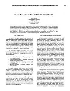
Feature modeling is based around the notions of concept and feature. A concept is an understanding of a class or category of elements in a domain. Individual elements that correspond to this understanding are called concept instances. A feature is an important property of a concept [CE00]. A feature may be common, in which case it is present in all concept instances, or variable, in which case it is present only in some concept instances. The features connected directly to a concept or feature are being denoted as its direct features; all other features are its indirect features [CE00]. Any feature may be isolated and modeled further as a concept. Hence, being a feature is actually a relationship between two concepts [Vra04]. However, the concepts identified only in the context of other concepts, i.e. as their features, will be referred to as features exclusively in order to emphasize the main concepts in a domain. There are many different feature modeling notations [Vra04]. Generally speaking, a feature model consists of a set of feature diagrams (one for each concept), additional information on concepts and features, and constraints and default dependency rules (associated with feature diagrams). A feature diagram is commonly understood as a directed tree, although it may also be considered to be a connected directed graph [Vra04, FN05], whose root represents a concept and the rest of the nodes represent its features. Feature diagrams constitute the most important part of a feature model and we will further in the paper concentrate on this part of the feature model. We will present the basic feature modeling notation by an example. Consider we are developing a family of peer-to-peer chat systems (Fig. 1). An important concept in such a system is a chat protocol. The chat protocol defines features available during a connection. For the purpose of this study, we will assume a simplified version of such a protocol. A user (Caller) sends a request for establishing a connection to another user (Connect).
P2P Connection
Privacy Caller Encryption Algorithm
Callee User
Connect Hide State
User
RSA
DES
Hide Personal Information Send Message
Encrypt Files
Send File
Encrypt Communication
Terminate Connection
Figure 1: Peer-to-peer chat protocol in Czarnecki-Eisenecker notation.
This request has to be accepted by the user being called (Callee). Any of the two participating sides may then send messages (Send Message) or terminate the connection (Terminate Connection). These features are mandatory and are a part of any P2P Connection concept instance. The concept of user is modeled separately with the basic features relevant to peer-to-peer chat systems (Fig. 2). This concept is referenced in the feature diagram of the P2P Connection concept. Concept references from should be distinguished from other features in R mark put after the name of a concept reference for a feature diagram. Here we use the this purpose. A concept reference is equivalent with the repetition of the whole feature diagram of the referenced concept. User
IP
Name
Picture
Figure 2: The concept of user referenced in the peer-to-peer chat protocol.
Optional features of the protocol include file transfer (Send File), encryption (Encrypt Connection), as well as some privacy management (Privacy). These features don’t have to be included in a concept instance, so we may have a communication system with restricted functionality that doesn’t support file transfer. Privacy support can be configured at finer level. A system can support hiding the user state (Hide State) or personal information (Hide Personal Information), or both, but at least one of these features has to be included if we include the (Privacy) feature. This is denoted by grouping these two features as or-features, which is denoted by a filled arc. The privacy
management may also include an encryption algorithm to be used throughout a system to encrypt messages and files. The diagram in Fig. 1 is in original Czarnecki-Eisenecker notation, which is based on FODA notation [KCH+ 90]. The same diagram in cardinality-based Czarnecki-Eisenecker notation is depicted in Fig. 3. Cardinalities were first introduced to non-grouped features based on practical experience [CBUE02]. Later, the notation was extended to include group cardinalities [CHE05] as proposed by Riebisch [RBSP02]. P2P Connection [0..1] [1..1] Caller [1..1] User
Privacy
[0..1]
[1..1]
Encryption Algorithm [1..1]
Callee
Connect [1..1]
Hide State
User
RSA
DES
Hide Personal Information
[0..1] Encrypt Files
[1..1] Send Message
[0..1] [0..1]
Send File
Encrypt Communication [1..1]
Terminate Connection
Figure 3: Peer-to-peer chat protocol in cardinality-based Czarnecki-Eisenecker notation.
In the contemporary version of this notation [CK05], features in a group are considered to have [0..1] cardinality (not shown in the diagram), but the cardinality may also be set to [0..0] or [1..1] to denote features eliminated or selected, respectively, from the group during specialization. Figure 4 (adapted from [Vra04]) demonstrates the use of cardinalities to define features that may be multiply included in a concept instance.1 The concept being modeled is a feature model itself. As we explained, a feature model consists of a set of feature diagrams (at least one), which is modeled by the Feature Diagram feature. We may also link feature model to zero or more other artifacts, which is modeled by the Link feature. In the original Czarnecki-Eisenecker notation, we would not be able to express cardinalities in a such straightforward way and we would be forced either to model cardinality as a feature [CE00] or to use the idiom shown in Fig. 5 that can be generalized for a full support of cardinalities based on open feature groups, concept references, and parameterized 1 The original notation for optional and mandatory features, as well as for alternative and or-feature groups, is also allowed and encouraged for its better readability in cardinality-based Czarnecki-Eisenecker notation, so it is applied here, too.
concepts [Vra04]. Feature Model New Feature Diagram Name
[0..*]
[1..*] Description
Feature Diagram
Delete Feature Diagram
Link
Normalize
Figure 4: Feature model concept (adapted from [Vra04]).
Feature Diagrams
... Feature Diagram 1
Feature Diagram 2
Feature Diagram
Feature Diagram
Figure 5: The plural form of the Feature diagram concept.
While we may expect further development of the notation, having cardinalities as a basis for expressing feature cardinality is unlikely to change. Moreover, we may imagine a family of notations based on cardinalities. Therefore, further in this paper we will concentrate on the core elements of the feature modeling and show how some notation-specific elements may be added.
3
Extending UML Metamodel with Core Feature Modeling Elements
The UML metamodel has been extended by adding new metaclasses and metarelationships that represent feature modeling elements. Since a feature model doesn’t bear any implementation connotation, the extension is based on the most abstract metaclasses. The extension preserves relationships of existing elements. Thus, a model based on the original UML metamodel will be correct in terms of the extended metamodel, too. The feature modeling extension is enclosed in its package denoted as FMConstructs. This package is merged into the Kernel UML package to assure its propagation throughout the language (see Fig. 6). The basis for all feature modeling elements is the FMElement abstract metaclass (see Fig. 7). By deriving it from the Element metaclass we avoid including any underlying semantics. Features constitute a subclass of FMElement. Each feature has to be named. The same feature name may be used across one feature diagram. Even siblings may share the same name which enables feature cloning as proposed in cardinality-based CzarneckiEisenecker notation [CHE05].
Figure 6: Merging package FMConstructs into Kernel [Obj05].
Using this extension, one can model feature diagrams as graphs. However, a common understanding is that strictly hierarchical organization of feature diagrams as directed trees each of which represents one concept is more beneficial than limiting. In our extension, this can be achieved by introducing a stereotype for the feature diagram root (sometimes called root feature). The relationship between a feature and its subfeatures is modeled by the SubfeatureRelationship metaclass as depicted in Fig. 8. To enable the use of feature cardinalities, the SubfeatureRelationship is based also on the MultiplicityElement. Feature group membership is defined as a relationship between the base feature and two or more subfeature relationships that belong to the group (see Fig. 9). To enable the use of
Figure 7: FMElement metaclass.
Figure 8: SubfeatureRelationship metaclass.
group cardinalities, the GroupRelationship is based also on the MultiplicityElement, as it was the case with SubfeatureRelationship. This is different from the cardinality-based Czarnecki-Eisenecker notation in allowing features in groups to have cardinalities, too. For pure cardinality-based Czarnecki-Eisenecker notation, cardinality 1 should be used. We find representing feature groups as sets of subfeature relationships (edges) to be a more appropriate solution than to represent them as sets of features (nodes), which is the ˇ solution we considered originally [Sni05]. This corresponds to understanding features as relationships between concepts as explained in Sect. 2.
Figure 9: GroupRelationship metaclass.
A mandatory feature could be defined as a stereotype of this relationship with cardinality , and optional features with cardinality along with their common graphical representation. Similarly, the most commonly used group cardinalities can be stereotyped as alternative () and or-features ().
4
Notation Specific Feature Modeling Elements
There are many notation specific extensions to feature modeling. Some approaches to feature modeling (e.g. FODA and FORM) use a layered representation of feature models.
In such approaches, each feature belongs to some layer according to its type. To facilitate this, we introduce the FMLayer metaclass derived from the FMElement metaclass. This class serves as a container of feature modeling elements. Number of layers is considered a method issue, so it is not prescribed in any way by the feature modeling extension.
Figure 10: Layers in feature models.
While design spaces approach to feature modeling offers a quite different graphical notation, it essentially enables to model a feature diagram in a FODA-style [Gey00]. This approach introduces a notion of feature correlation that represents a form of expressing additional constraints between features. A correlation may be weak or hard. A weak correlation constitutes a recommendation to combining features in the form of a floating point number in the range [-1, 1]. A hard correlation is represented as a boolean value (combine or do not combine). Similarly as feature groups, a correlation is based upon subfeature relationships rather than features themselves.
Figure 11: Correlation between features.
5
Feature Modeling Profile for UML
Contemporary UML modeling tools do not enable to modify the UML metamodel. It is possible only to extend UML using profiles as stereotyped packages. Profiles represent
so-called lightweight extensions and may employ stereotypes, tagged definitions and constraints as extension mechanisms [Obj05]. We created a UML 2.0 profile2 to facilitate experimenting with combining different feature modeling notations. With this profile, we are not trying to mimic a correct integration of feature modeling into UML, which we presented in the metamodel we proposed in previous sections. In our profile feature models are represented as trees, which is a common practice. Thus, each diagram has a root node which represents a concept. A concept is modeled as a stereotype of the Artifact metaclass (see Fig. 12). A feature is modeled as a component (see Fig. 13).
Figure 12: Elements based on Artifact.
Figure 13: Feature.
Subfeature relationships (mandatory, optional, and a general cardinality-based relationship) are modeled as Dependency metaclass stereotypes (see Fig. 14). Mandatory and optional relationships are separate from the features as such (nodes), while in cardinalitybased relationship two tagged values at a feature are used to denote its cardinality as in cardinality-based Czarnecki-Eisenecker notation. Since it n-ary relationships are not supported by modeling tools, feature groups are modeled as variation points. They are based on Artifact metaclass (see again Fig. 12). Three types of feature groups are defined in the profile. AlternativeVariationPoint enables to define an alternative feature group with the possibility to set the minimal number of features to be selected as a tagged value. Similarly, OrVariationPoint enables to define an or-feature group with the possibility to set the maximal number of features to be selected as a tagged value. Finally, GroupDependency enables full control 2 Feature modeling profiles for Enterprise Architect and Omondo UML are available at http://fiit. stuba.sk/∼vranic/fm/.
over the group cardinality with tagged values as specified by the cardinalitybased Czarnecki-Eisenecker notation.
Figure 14: Subfeature relationships.
The profile also embraces the two notation-specific extensions embraced in the metamodel extension (see Sect. 3): layered feature models (as in FODA or FORM) and correlation relationship (see Fig. 15). A layer is modeled as a package stereotype. Only a weak correlation from design spaces notation is included and it is modeled as an association stereotype with the tagged value in the range [-1, 1].
Figure 15: Notation-specific extensions in the UML feature modeling profile.
6
Related Work
There are several known UML extensions for feature modeling, but all represent lightweight extensions like our UML profile presented in the previous section, which inevitably adds undesired semantics to feature modeling elements. Such approaches have been characterized as “diagram hacking” by Czarnecki and Eisenecker [CE00], but may serve well as a solution at hand for feature modeling using UML modeling tools. On the other hand, we are not aware of any attempt to provide a unifying basis for different feature modeling notations. Clauβ employs a straightforward solution to extending UML with feature modeling by representing a concept and feature as class stereotypes [Cla01]. Features themselves bear the information on variability expressed by three different stereotypes: , optional>>, and alternative>>. The most significant problem with Clauβ’s approach lies in modeling feature relationships using aggregation and generalization, which forces to make design decisions during do-
main analysis phase in which feature models are being created. Furthermore, alternative features actually represent or-features3 , while real alternative features (xor) are achieved by applying {xor} constraint to the respective edges. These constraints may be used to partition subfeatures of a feature into several groups of alternative features, but there is no way to denote several independent or-groups at one feature. This may be bypassed using the mechanism of an explicit variation point, which is also a class stereotypes. Variation points enable to set the maximal number of features to be selected, similarly to the solution we used in our profile (see Sect. 5). In his approach to designing software product lines with UML [Gom05], Gomaa proposes to model features as use case packages or as stereotyped classes, depending on intended use of the model. Stereotyped classes approach, with feature groups modeled with aggregation, suffers from the problems pointed to above. The use case representation brings an interesting perspective. However, it is useful mainly in the context of the elaboration of mapping of features to use cases, which is an important point of Gomaa’s approach. In approach of Griss et al., class stereotypes are used to express features, too, but there is no separate notion of concepts [GFd98]. Thus, it is possible to have a feature model as a general graph. The character of the feature—along with its variability—is modeled by class attributes. One of the attributes enables to set a feature to act as a variation point of alternative features, which brings again the limitation of having only one subfeature group per feature. The subfeature relationships are modeled as dependencies with the stereotype. Dolog’s approach is also based on class stereotypes representation of features [DN04, Dol06], but it employs a thorough treatment of feature groups through variation points. This approach actually supports feature diagrams in the form of directed acyclic graphs, but the information on variability is still inadequately built into the features themselves.
7
Conclusions and Further Work
Feature modeling is gaining more popularity along with rising awareness of the importance of software product lines. This is mainly due to its ability of dealing abstractly with configurability. Having UML as a de-facto standard modeling language, it becomes necessary to have feature modeling as part of it. In this paper we presented an approach to integrate feature modeling into UML by extending its metamodel. We focused on making a basis for further development of the feature modeling extension. For this, it was crucial to assure abstractness of feature modeling elements. With our feature modeling extension, based on the cardinality-based Czarnecki-Eisenecker notation, we were also addressing the objective of providing a basis for different notationspecific feature modeling extensions. To facilitate experimenting with combination of different feature modeling notations in UML modeling tools, we developed a UML profile. 3 They
are denoted as “non-exclusive alternatives,” contrary to the meaning of the word alternative.
While we are aware it is not possible to achieve abstractness of feature modeling elements this way, our profile’s advantage is modeling feature variability as relationships between features which we consider to be a more correct solution compared to having this information as part of the nodes that represent features. The metamodel we presented in this paper forms a basis for feature modeling in UML. Further work will include introducing concept references and covering additional information on concepts and features, such as including description and binding time information. It is also inevitable to treat constraints and default dependency rules. This issue has already being explored and it seems quite reasonable to represent additional constraints as logical expressions [Vra05, Vra04], which in the context of UML may be successfully implemented in OCL [CK05, SRP03]. Also, we will continue to experiment with other notation-specific extensions in our feature modeling UML profile. Acknowledgements The work was supported by Slovak Science Grant Agency VEGA, project No. 1/3102/06, and Science and Technology Assistance Agency of Slovak Republic under the contract No. APVT-20-007104.
References [CA05]
Krzysztof Czarnecki and Michal Antkiewicz. Mapping Features to Models: A Template Approach Based on Superimposed Variants. In Robert Gl¨uck and Michael R. Lowry, editors, Proc. of Generative Programming and Component Engineering, 4th International Conference, GPCE 2005, LNCS 3676, pages 422–437, Tallinn, Estonia, October 2005. Springer.
[CBUE02] Krzysztof Czarnecki, Thomas Bednasch, Peter Unger, and Ulrich W. Eisenecker. Generative Programming for Embedded Software: An Industrial Experience Report. In Don Batory et al., editors, Generative Programming and Component Engineering: ACM SIGPLAN/SIGSOFT Conference, GPCE 2002, LNCS 2487, pages 156—-172, Pittsburgh, PA, USA, October 2002. [CE00]
Krzysztof Czarnecki and Ulrich W. Eisenecker. Generative Programing: Methods, Tools, and Applications. Addison-Wesley, 2000.
[CHE05]
Krzysztof Czarnecki, Simon Helsen, and Ulrich Eisenecker. Staged Configuration Through Specialization and Multi-Level Configuration of Feature Models. Software Process: Improvement and Practice, 10:143–169, April/June 2005.
[CK05]
Krzysztof Czarnecki and Chang Hwan Peter Kim. Cardinality-Based Feature Modeling and Constraints: A Progress Report. In International Workshop on Software Factories, OOPSLA 2005, San Diego, USA, October 2005.
[Cla01]
Matthias Clauß. Modeling Variability with UML. In Proc. of Net.ObjectDays 2001, Young Researchers Workshop on Generative and Component-Based Software Engineering, pages 226–230, Erfurt, Germany, September 2001. tranSIT.
[DN04]
Peter Dolog and Wolfgang Nejdl. Using UML-Based Feature Models and UML Collaboration Diagrams to Information Modelling for Web-Based Applications. In Thomas
Baar Alfred Strohmeier Ana Moreira and Stephen J. Mellor, editors, Proc. of Seventh International Conference on the Unified Modeling Language: Modeling Languages and Applications (UML 2004), LNCS 3273, pages 122–137, Lisabon, Portugal, October 2004. Springer. [Dol06]
Peter Dolog. Engineering Adaptive Web Applications. PhD thesis, University of Hannover, Germany, 2006.
[FN05]
Roman Filkorn and Pavol N´avrat. An Approach for Integrating Analysis Patterns and Feature Diagrams into Model Driven Architecture. In SOFSEM, pages 372–375, 2005.
[Gey00]
Lars Geyer. Feature Modelling Using Design Spaces. In Proc. of the 1st German Product Line Workshop (1. Deutscher Software-Produktlinien Workshop, DSPL-1), Kaiserslautern, Germany, November 2000. IESE.
[GFd98]
Martin L. Griss, John Favaro, and Massimo d’Alessandro. Integrating Feature Modeling with the RSEB. In P. Devanbu and J. Poulin, editors, Proc. of 5th International Conference on Software Reuse, pages 76–85, Vicoria, B.C., Canada, 1998. IEEE Computer Society Press.
[Gom05]
Hassan Gomaa. Designing Software Product Lines with UML. Addison-Wesley, 2005.
+
[KCH 90] Kyo C. Kang, Sholom G. Cohen, James A. Hess, William E. Novak, and A. Spencer Peterson. Feature-Oriented Domain Analysis (FODA): A Feasibility Study. Technical Report CMU/SEI-90-TR-21, Software Engineering Institute, Carnegie Mellon University, Pittsburgh, USA, November 1990. ˇ [Sni05]
ˇ J´an Snirc. Integrating Feature Modeling into UML. Master’s thesis, Slovak University of Technology in Bratislava, 2005. In Slovak. Available at http://fiit.stuba. sk/∼vranic/.
[Obj05]
Object Management Group. UML 2.0 Superstructure Specification. Technical report, August 2005. Available at http://www.uml.org/, last accessed in February 2006.
[RBSP02] Matthias Riebisch, Kai B¨ollert, Detlef Streitferdt, and Ilka Philippow. Extending Feature Diagrams with UML Multiplicities. In Proc. of the 6th Conference on Integrated Design and Process Technology (IDPT 2002), Pasadena, California, USA, June 2002. Society for Design and Process Science. [SRP03]
Detlef Streitferdt, Matthias Riebisch, and Ilka Philippow. Details of Formalized Relations in Feature Models Using OCL. In Proc. of the 10th IEEE Symposium and Workshops on Engineering of Computer-Based Systems (ECBS’03), pages 297–304, Pasadena, California, USA, April 2003. IEEE Computer Society.
[Vra04]
Valentino Vrani´c. Reconciling Feature Modeling: A Feature Modeling Metamodel. In Matias Weske and Peter Liggsmeyer, editors, Proc. of 5th Annual International Conference on Object-Oriented and Internet-Based Technologies, Concepts, and Applications for a Networked World (Net.ObjectDays 2004), LNCS 3263, pages 122–137, Erfurt, Germany, September 2004. Springer.
[Vra05]
Valentino Vrani´c. Multi-Paradigm Design with Feature Modeling. Computer Science and Information Systems Journal (ComSIS), 2(1):79, June 2005.