(CNTs) [9] and Tunneling Phase logic (TPL) [10], all have the potential to replace the current ... K-MAP BASED KNOWLEDGE MODULE ... class is sufficient for the concepts introduced in this module, hence additional books or reference.
1
Integrating Nano-logic Knowledge Module into an Undergraduate Logic Design Course Saket Srivastava, Student Member, IEEE and Sanjukta Bhanja, Member, IEEE
Abstract—This work discusses a knowledge module in the undergraduate logic design course introduced to electrical engineering and computer science students exposing them to nano-computing concepts. This knowledge module has a two-fold objective. First, it generates interest amongst students regarding the fundamental logical behavior and functionality of future nano-devices. This will motivate them to enroll in other elective courses related to Nanotechnology, being offered in most EE and CS departments. Further, this module can be used to let students analyze, synthesize and apply their existing knowledge of Karnaugh-map based Boolean logic reduction scheme into revolutionary design context with majority logic. Where many efforts focus on developing new courses on nanofabrication and even nano-computing, this work intends to augment the existing standard EE and CS courses by inserting knowledge modules on nano-logic structures in order to stimulate student interest without significant diversion from the course framework.
Index Terms—logic design, K-maps, majority logic, QCA
I. INTRODUCTION There is a consensus among the computing researchers that CMOS devices will stop scaling
2
sometime around the year 2020 [7]. Some of the promising technologies such as Quantum-dot Cellular Automata (QCA) [6] [15], Single Electron Transistors (SETs) [8], Carbon Nanotubes (CNTs) [9] and Tunneling Phase logic (TPL) [10], all have the potential to replace the current generation CMOS. It is very difficult to tell in advance which particular technologies or their variants are going to become important for system designers in coming years. What is necessary is for students to recognize that technologies change and that they must adapt to those changes. The learning module described by this paper is an example of one of the directions in which students might need to adapt. Furthermore, the introduction to some nano-computation concepts seems worthwhile for students of electrical engineering (EE) and computer science (CS) in order to have the knowledge of future nano-devices and the logic associated. Logic design students in both EE and CS will have to design circuits in these technologies based on the logic associated with them. The logic primitive for one nano-device might not be the same for another. For example, in QCA [6] [16], the most optimum designs are those that make use of majority logic. Similarly, while using SET and TPL, minority gate logic design is used to implement circuits [2]. Apart from the logic associated with these new technologies, students also need to be aware of design methods that can make use of present Boolean logic designs and transform them into logic associated with the future technologies. Several research efforts are currently underway on logic level and circuit level designs of these nanotech devices. The goal of this study is to augment the existing courses with flavors of the nanotechnology in a friendly, abstracted manner. This generates interest amongst students and motivates them to enroll in other existing nanotechnology courses [3]. This work aims to provide a seamless learning curve to the students to maximize the gains they obtain from this knowledge module without hindering their normal learning curve. In order to achieve this, the concept of majority network was introduced in the class following the Karnaugh map (K-map) based logic minimization techniques (for AND-OR logic). Since K-maps are an
3
integral part of any logic design curriculum, this was the right context to introduce the students to nano-computing. The educational experiments are set to not only expose the students to newer technology but also to test the synthesis and comprehension skills on the learnt K-map in previous lectures. The knowledge module consists of three parts. Initially, students are introduced to some novel nanodevices and logic primitives for such technologies. Next, they analyze simple majority logic design examples that enable usage of familiar logical concepts to perform simple analysis. Finally, the students use the knowledge obtained in the first two parts to design a small circuit using a novel algorithm showing a higher level comprehension, synthesis and application. At each step there needs to be a smooth transition between consecutive stages of the module to maximize learning by applying familiar logic design concepts. Worksheets assignments are handed out at each step of the module to evaluate student learning. Finally, an abstracted view of QCA logic and functionality is demonstrated to motivate students into nano-device and nano-computing research. At every step, apart from exposing students to nanotechnology, the goal of this work is to enhance their critical thinking by reinforcing the known idea and synthesis of novel logic structures applying the logic design concepts that they are familiar with. This will help the students understand how existing design techniques can be adapted to new technologies. This knowledge module was introduced in two semesters (Fall 2006 and Spring 2007) thus creating a broader base of students to evaluate the outcome as well as the progress. II. DIGITAL LOGIC DESIGN COURSE The knowledge module on nano-computing resides in the undergraduate logic design course. This course is offered twice a year (Fall and Spring). The class consists of two one and a half hours of lectures per week. This is one of the core courses for electrical engineering students and
4
a pre-requisite for a number of advanced courses such a CMOS VLSI design and microprocessor design. Students taking this course are usually in their sophomore or junior year. Most of the students are not yet familiar with Boolean logic and current technology being used in the industry to design circuits. Since this is the first course of this type that they undertake, their interest in this course will determine their future in this area. This course deals with number systems and the basic arithmetic operations. Also, this is the first time students are exposed to 2’s complement and 1’s complement addition and subtraction. Students are also taught various logic reduction schemes, one of which is K-maps. They are supposed to design small subsystems like adders, multiplexers and the course is concluded with basic sequential circuit design. Since this course is an introduction to digital logic and computing, a flavor of nano-logic was introduced in this course. III. K-MAP BASED KNOWLEDGE MODULE The knowledge module discussed in the work was presented to the students over a period of two lectures each of which is one and a half hours in length. The lecture materials for this module include power point presentations and worksheet assignments. The material presented in the class is sufficient for the concepts introduced in this module, hence additional books or reference material was not recommended. This is also evident from the student feedback received. The students however were directed to visit some websites [1] [11] [12] [13] that provide tutorials for nanotechnologies discussed in this module.
A. Intellectual Merit The intellectual merit of this work is two-fold. The aim is to motivate students in electrical engineering towards future technologies, and also to reinforce their knowledge in K-maps. This module helps them apply their knowledge of K-maps into a novel majority logic synthesis application and helps to improve their analytical skills.
5
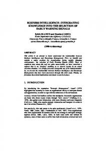
In the beginning of this knowledge module the study of various promising nanotechnologies that are being researched was presented to the students. Since this is a design oriented course, students are not required to be overwhelmed with the fabrication details of the technology. Focus is rather on the functionality and logic associated with the technology. Some interesting technologies such as QCA, CNT and SET were short-listed for this purpose. The primary reason to choose these three technologies is that all three of them use different logic schemes for implementation. While QCA uses majority logic, CNT implements traditional NAND logic and SET uses minority logic. Fig. 1 shows the schematic representation of these devices.
P=-1
P = +1
(a)
(b)
(c)
Fig. 1. (a) Schematic of a QCA cell (b) A Carbon Nanotube Transistor (CNT) (c) Schematic of a Single Electron Transistor (SET)
Each of these devices is based on novel concepts. QCA uses columbic interaction between adjacent QCA cells to transfer information rather than flow of charge used in current technologies. While CNT technology uses similar logic concepts as CMOS, it has a completely different implementation which uses carbon allotropes unlike silicon used in the current technology. SET technology uses a very novel concept called “coulomb blockade” to perform logical operations. Since the knowledge module spanned over two lectures, it was not possible to educate the students about the quantum mechanical properties of these devices. Major focus of this work is to abstract the logical behavior of these devices and present it to the students in a way that is easy
6
to comprehend. The algorithm used in this module is difficult for students of this class to understand. The algorithm uses a multi-level iterative design procedure which is beyond the scope of the undergraduate logic design course. Hence to simplify the complexity of this algorithm and use it in the class, it was first solved for a number of common logic expressions such as an even parity generator and an odd parity generator. These expressions are regularly used in the undergraduate logic design class and students are quite familiar with them. Next, the instructor demonstrates this algorithm to the students with these simple examples and asked students to design a new circuit based on that. The objective is to let the students understand the algorithm without getting overwhelmed with the iterative procedure used to optimize the logical function. In order to enable students to use the algorithm they were only provided with a library of five such K-map patterns (overall 38 such patterns could be there). Students needed to choose three patterns to out of the five provided to effectively represent a Boolean logic function into a majority logic function. This module also intends to work as a reinforcement of their digital logic concepts namely algebraic manipulation, logic minimization and the true meaning of min-terms. The students were able to synthesize and apply the knowledge of achieving irredundant prime-implicants into achieving minimum majority network.
B. Teaching Methodology The teaching methodology is three-fold. The instructor first demonstrates on how students can relate the already familiarized Boolean logic concepts to logic associated with other nanodevices. This step helps the students grasp the underlying idea behind the new information and relate it to the information they have learnt in the previous lectures of this class. It will also help them reinforce the existing knowledge, thus resulting in increased information acquisition and retention.
7 x1’ f1
n = f 1+ f 2
0
f 1 = x1 '• x3 ' f 2 = x2 • x3 '
x3’
f1
x1’ 0
n
1
x3’
x3’
n 1 0
x3’ 0
f2
x2
f2 x2
(a)
(b)
Fig. 2. AND/OR mapping of a Boolean Logic function n = x1’.x3’+x2.x3’
Secondly, students are shown how they can use this acquired knowledge to analyze the new logic style by making use of a simple AND/OR mapping scheme. Since students are already familiar with AND/OR gates, they often find it really interesting how the same type of analysis can
n = f 1 • x3 ' f 1 = x1 '+ x2 x1’ 1 x2
0
x1’ f1
n
1
f1 n 0 x3’
(a)
x2
x3’
(b)
Fig. 3. AND/OR mapping of reduced Boolean logic function n = x1’.x3’+x2.x3’ = (x1’+ x2) x3’
be performed using majority logic. This step helps the students visualize and analyze the new logic style with a minimum diversion, and it was observed that this step has great impact on student learning (discussed in section III). It is important for students to realize that while logic styles might change when technology changes, the inherent concepts regarding design styles remain the same.
8
Students are taught how a 3-input majority gate can be represented as an AND or OR gate by fixing one of its inputs as a 0 or 1 respectively as shown in Fig 2(a). In this way students are able to visualize and synthesize small Boolean circuits using majority gate logic just by representing each AND and OR gate by its equivalent majority gate. Fig. 2(b) shows QCA implementation [1] for the Boolean expression mapped by AND/OR logic in Fig 2(a). It was also emphasized that any Boolean function can be implemented by using majority gates and inverters. Fig 3(a) shows the AND/OR mapping of a reduced Boolean logic function (shown in Fig. 2) and Fig 3(b) shows its QCA implementation. As a final part of this logic module, students were asked to perform a relatively complex design algorithm by applying the already-known K-map to the new logic style to which they have been recently exposed in the earlier part of this module.
C. K-maps in Logic Design Course K-maps are the graphical representation used for reduction of complex logical expressions to a reduced form. K-maps are one of the most essential elements of any Digital logic design curriculum. They facilitate learning by representing information in a graphical format that is easier to comprehend, analyze and evaluate. The patterns that the students are looking at traditionally in a logic design course are connected to AND-OR logic and the patterns resemble squares/rectangles of 2m by 2n cells due to the algebraic adjacency. However for majority logic the patterns are of irregular shape and students need to understand and comprehend the differences and similarities between the logic styles.
9
A Boolean logic function can be minimized by mapping all the zeros and ones in the truth table to a K-map. Adjacent ones are combined as a rectangular group in the K-map, each representing a min-term. The ones in a K-map are grouped by first trying the largest 2p group and then grouping them in decreasing order of 2p-1, 2p-2 and so on. This grouping is done only on a rectangular or square matrix of 2m by 2n cells. In this way each one mapped on the K-map has to be covered and each group represents a min-term of the reduced Boolean logic function.
ab
00
01
11
10
0
0
0
1
0
1
0
1
1
1
c
a b b c
(a)
c 0 1
00 0
M1
c a
f = ab M1 + bc + ca
ab
f
(b) M2
F(a,b,c)
M2
01
11
0
1
10 0
F(a,b,c) Maj (M1,M2,M3)) a
f
Maj (M1,M2,M3))
b 0
1
1
1
c
M3
M3 ( a , b , c ) f = M
(c) (a)
(d) (b)
Fig. 4. (a) Grouping of 1’s in a K-map for Boolean reduction (b) AND/OR schematic of the reduced Boolean expression (c) of 1’s in a K-map for implementation a majority logic andexpression (d) a majority gate equivalent the reduced K-map Fig.grouping 4. Schematic diagram and QCA of design a Boolean represented in majorityoflogic. expression.
In order to change a Boolean logic function to a majority logic function, the ones are not grouped in the way described above; rather they are grouped according to one of the shapes in the pre-built library of 38 such shapes. Each shape in the library denotes a majority logic function of at most three variables. Fig. 4(a) shows how a logic expression mapped on a K-map will appear in the reduced form in Boolean logic. It can be seen that the reduced Boolean expression contains three min-terms, where each min-term is a group of two adjacent ones. Since all the four ones cannot be grouped in a matrix of 2x2 hence they are grouped in three matrices of 2x1. Each grouping represents a
10
min-term in the reduced expression. The schematic of reduced expression is shown in Fig. 4(b). Fig. 4(c) shows that all the four ones can be grouped together to represent a majority gate of three variables. The schematic of a three input majority gate (derived from the K-map) is shown in Fig. 4(d).
D. Algorithm The algorithm demonstrated for majority logic in [2] is complex to understand and had to be simplified significantly to enable undergraduate logic design students to understand and implement it in their worksheets. The algorithm makes use of a library of 38 predetermined K-map patterns. An iterative algorithm then chooses three most optimum K-map patterns each of which represents a majority logic function (M1, M2 and M3). Using [4] it as been proven that any three input logic function f can be represented using a maximum of four majority gates.
f (a, b, c) =M(M1,M2,M3)
Fig. 4(a) shows the schematic of a majority logic function obtained after using the algorithm that reduces a complex three input Boolean logic function to a majority logic function. Fig. 4(b) shows the QCA implementation of a four majority gate design derived using the K-map based design algorithm discussed above. In the next section, the impact of this knowledge module is evaluated based on the performance of students in each of the worksheets handed out to them. IV.
EVALUATION
In order to evaluate the level of understanding that students gained from this course module, they were given worksheets at the end of each step of this knowledge module. This study follows
11
the Bloom’s taxonomy [5] in the cognitive domain while formulating these worksheets in order to maximize the gains to the students.
The cognitive domain deals with the development of
knowledge and development of intellectual attitudes and skills.
A. Worksheet Details Worksheet-1 evaluated their understanding of QCA majority logic. This worksheet gives an idea about the interest and the level of understanding shown by the class to the new concepts. For the students, this worksheet evaluates information acquisition of a novel concept. This worksheet deals with the knowledge and comprehension skills. Worksheet-2 evaluated their level of understanding to perform an AND/OR mapping of simple Boolean expressions. This worksheet helps the students not only perform the simple design, but also evaluates the seamless transition between known concepts using old logic style to a novel logic style. This worksheet deals with the application and analytical skills of the students. Finally, in worksheet-3, students were asked to perform a K-map based synthesis method to reduce a complex three input logic function. Students were also asked to perform an AND/OR mapping for the same function to understand the advantage of K-map based method over AND/OR mapping method. Not only does this worksheet challenge the analytical skills of the students to apply the knowledge attained in this course to a totally new logic style, it also enhances their critical thinking by reinforcement of known ideas. They see how K-maps while being an important part of logic design curriculum can also be used as a design tool for other logic styles. This worksheet falls under the category of synthesis skills (different from majority logic synthesis discussed above) in the cognitive domain.
12 TABLE I RESULTS OBTAINED FOR EACH WORKSHEET IN FALL 2006 AND SPRING 2007
Worksheet
Grade A
1 2
F06 81.25 68.75
S07 59.09 50.00
3
37.5
76.00
Percentage of students receiving grade Grade B F06 S07 18.75 31.82 31.25 31.82 25
12
Grade C F06 0 0
S07 9.09 18.18
37.5
12
B. Evaluation of Worksheets This knowledge module was first introduced in digital logic design course to undergraduate electrical engineering students in Fall 2006. The results of worksheets and feedback were quite encouraging and it was decided to introduce this module again in Spring 2007 semester. The results of grades assigned to students in all three worksheets are tabulated in Table I. • In worksheet-1, 81.25% students were able to complete each problem (Grade A) in Fall 2006 as compared to 59.09% in Spring 2007. Overall, students of Fall 2006 semester were able to grasp QCA concepts better. • In worksheet-2, 68.75% students were able to complete each problem (Grade A) in Fall 2006. In Spring 2007, 50% of students received Grade A. • In worksheet-3, interestingly in Spring 2007 percentage of students that were able to understand the synthesis algorithm properly and achieve a Grade A doubled as compared to Fall 2006. A lack of control group makes it a difficult task to evaluate the pedagogical goals achieved from this work. A thorough study in this regard would take a few years to track the enrollment of students in elective nanotechnology courses and also in the nanotech research programs offered in the college of engineering. Table I shows the results of graded worksheet assignments of the two sample groups.. In order to gain more insight on the relevance of worksheet results presented in this study, a ttest analysis was performed on all the three worksheets to assess if the data from of two sample
13
groups are statistically different from each other. The results of this t-test are shown in Table II. For the purpose of evaluation numerical grades were assigned to each letter grade that the students received in the worksheets (A=4, B=3, C=2 and D=1). The mean, standard deviation and two-tailed p-values were then calculated using this data to calculate the statistical significance. Data from the first two worksheets show that for both the groups students performed equally well (statistical diversity is very low, p-value>0.05). For worksheet-3, both the groups showed sufficient understanding of the complex algorithm; however the second group performed significantly better than the first group (p-value < 0.05). One of the reasons for this could be the fact that in Spring 2007, this knowledge module was introduced a few classes after they were taught K-maps and hence by then they were already very comfortable with the K-maps and found it challenging to solve new problems using those. TABLE II STATISTICAL EVALUATION OF STUDENTS IN THE TWO SEMESTERS BASED ON THE T-TEST RESULTS
Worksheet
Number of Samples
Average Grade
Standard Deviation of Grades F06 S07 0.40 0.67
Two-tailed p-value
1
F06 16
S07 22
F06 3.81
S07 3.50
2
16
22
3.69
3.32
0.48
0.78
0.103
3
16
25
3.00
3.64
0.89
0.70
0.014
0.107
Despite the difference in grading patterns of the two semesters, it was interesting to see that students from both classes were very motivated towards learning more about Nanotechnology and were very comfortable in using their K-map knowledge and applying it for majority logic design. This is evident from the feedback received from the students as discussed in the next section. V. FEEDBACK FROM STUDENTS At the end of each semester student’s response was collected as a feedback survey. The objective of this feedback was manifold. Even though the worksheet assignments were graded,
14
they only provide an idea of the level of understanding the students gather from this knowledge module. Feedback survey helps in knowing their perspective and ideas to improve this course module as well as to evaluate if it was able to achieve the desired objectives. As per the Bloom’s taxonomy, this feedback survey along with the results of graded worksheets falls under the evaluation skills. Feedback Questions: 1. How did you find the lecture on Nano Logic? 2. How comfortable you were in extending K-map knowledge and apply it to nanotechnology? 3. How well did you comprehend the lectures? 4. How did you find worksheet assignments on logic flow in QCA? 5. Would you have liked to have more classes on Nano-logic devices? 6. Do you think these lectures were helpful in motivating you to study more on these devices? 7. Do you think Nano-logic should be made a part of curriculum in future logic design classes?
Since this knowledge module has a two-fold objective, Question-2 and Question-6 are of particular interest. In Question-2, an overwhelming 86% of the students were able to use K-map knowledge for majority logic synthesis. Around 42% could do it easily while almost 44% of the class could do it with some effort. In Question-6, an overwhelming 89% of the students showed motivation to learn more about future nanotech devices. While 23% said that the lectures were very motivating, another 66% developed an interest in the subject and thought them to be useful. The other feedbacks show that students are very keen to learn more about nanotechnology and logic associated with it. Majority of them suggested that it was a good idea to introduce it and that they would even like to see it as a part of the EE curriculum. Table III and Table IV show the
15
pie-charts for each question asked in the survey. The size of the survey includes students from both the semesters. This provides a broader base for the feedback. TEACHING MATERIALS The supplementary teaching materials with guidelines to use them will be available on the website: http://www.eng.usf.edu/~bhanja/nanologic.htm. The website [14] also contains copies of graded worksheets and feedback surveys. A number of links to other websites, that have plenty of useful resources and teaching material, are also provided. The website content will be continuously updated each semester or whenever the knowledge module is altered for different nanotechnologies. TABLE III PIE-CHARTS OF STUDENTS RESPONSE TO THE FEEDBACK SURVEY. SAMPLE SIZE INCLUDES STUDENTS FROM BOTH THE SEMESTERS. QUESTION 1 TO QUESTION 4 Question 1: How do you find the lecture on Nano-logic in this class? Not Interesting at all 2%
Question 2: Did you feel comfortable in extending the Kmap knowledge and apply it to Nanotechnology? I was not able to figure it out 7%
I don't care 2%
Very Interesting 56%
Yes, very comfortable 42%
Not comfortabIe at all 5% Comfortable 46%
Interesting 40%
Question 3: How did you comprehend the lectures? Did not understand anything at all 5%
I understood everything 14%
I think I know what was being lectured. 19%
Question 4: How did you find the worksheet assignments on logic flow in QCA logic? Neither able to understand the concepts nor complete the worksheet. 2% Difficult to understand the concept and to complete the worksheet. 9%
Simple to understand the concept, but worksheets were hard 16%
Understood quite a bit 62%
Simple to understand and I was able to complete the worksheets 73%
16
TABLE IV PIE-CHARTS OF STUDENTS RESPONSE TO THE FEEDBACK SURVEY. SAMPLE SIZE INCLUDES STUDENTS FROM BOTH THE SEMESTERS. QUESTION 5 TO QUESTION 7 Question 6: Do you think that these Iectures were helpful in motivating you to study more on these devices?
Question 5: Would you have liked to have more classes on different types of Nano logic devices?
It'll be more like a burden on us to understand and study 5%
I don't care 9%
I don't think it is fruitful at all 5%
I do not think they were interesting or motivating 2%
It would be really interesting and fruitful 67%
It would be interesting but I am not sure that it would be easy to understand. 23%
Yes, they motivated me 23%
I feel they were interesting and would be usefull to me 66%
Question 7: Do you feel that Nano logic should be made a part of curriculum for future Logic design classes? It am against it 2% Maybe 23%
I feel very strongly 40%
I think it would be interesting 35%
VI.
CONCLUSION
This module will serve as a good resource for faculties teaching logic design classes. The results from worksheets and the feedback survey suggest that this work achieved the desired objectives. Students showed motivation towards learning more about nanotechnology and nanocomputing in an effective and understandable way. It also strengthened their knowledge in Kmaps and helped them develop cognitive skills to apply this knowledge in a very novel way. The deliverables of this work are the lecture notes, sample student worksheets and feedbacks. In
17
future semesters students will be introduced to other promising nano-logic devices such as SET and TPL and logic associated with them.
REFERENCES [1] QCADesigner,www.qcadesigner.ca [2] Zhang R; Gupta, P; Jha, N K, "Synthesis of majority and minority networks and its applications to QCA, TPL and SET based nanotechnologies," 18th International Conference on VLSI Design., 3-7 Jan. 2005, pp. 229- 234 [3] Minsu Choi; Park, N., "Teaching nanotechnology by introducing crossbar-based architecture and quantum-dot cellular automata," Microelectronic Systems Education, 2005. (MSE '05). Proceedings. 2005 IEEE International Conference on , vol., no.pp. 29- 30, 12-14 June 2005 [4] S. B. Akers, “Synthesis of combinational logic using three-input majority gates,” in Proc. Third Annual Symp. Switching Circuit Theory & Logical Design, Oct. 1962, pp. 149–157. [5] Bloom B. S. (1956). Taxonomy of Educational Objectives, Handbook I: The Cognitive Domain. New York: David McKay Co Inc. [6] P. D. Tougaw and C. S. Lent, "Logical devices implemented using quantum cellular automata," J. Applied Physics, vol. 75, no. 3, pp. 1811--1817, Feb. 1994. [7] International Technology Roadmap for Semiconductors, 2006. [8] M. A. Kastner, “The single-electron transistor”, Rev.Mod. Phys. 64, 849 (1992). [9] Adrian Bachtold, Peter Hadley, Takeshi Nakanishi, and Cees Dekker “Logic Circuits with Carbon Nanotube Transistors”, Science 294 (5545), 1317, 9 November 2001 [10] H. A. Fahmy and R. A. Kiehl, "Complete logic family using tunneling-phase-logic devices," in Proc. Int. Conf. Microelectronics, Nov. 1999, pp. 22--24.
18
[11] Nanohub - http://www.nanohub.org/ [12] QCA Homepage - http://www.nd.edu/~qcahome/ [13] UVA Virtual Lab - http://virlab.virginia.edu/VL/QCA_cells.htm [14] http://www.eng.usf.edu/~bhanja/nanologic.htm [15] C.S. Lent, P.D. Tougaw, W. Porod and G.H. Bernstein “Quantum cellular automata” NANOTECHNOLOGY 4, pp. 49-57 (1993) [16] R. Zhang, K. Walus, W. Wang, and G. A. Jullien, "A Majority Reduction Technique for Adder Structures in Quantum-dot Cellular Automata", Copyright SPIE International Symposium on Optical Science and Technology, paper 5559-10, Denver, CO, August 2-6, 2004.