Integrating Presence and Location Services using SIP Jamey Hicks, Andrew Christian, Brian Avery HP Laboratories Cambridge HPL-2005-115 June 14, 2005*
internet telephony, location awareness, session initiation protocol, wireless tracking
In semi-nomadic professions such as medicine, practitioners move through office buildings carrying personal computing and communication devices. These practitioners make use of fixed computing and communication resources in the rooms they visit. Organizations have strong financial incentives to help their mobile professionals find each other, communicate effectively, and make efficient use of the infrastructure. The challenge is to provide the desired functionality in a cost-effective manner without requiring special hardware on the mobile devices. Our solution consists of a standards-based voice, video, and instant messaging communication system integrated with a location tracking system. Our location tracking system is a low-cost scanning network that monitors the wireless network transmissions from the mobile devices and uses that information to identify and track the mobile clients. This paper describes (1) the architecture, implementation, and performance tradeoffs for a low-cost sensor network for live tracking of 802.11 wireless clients in an office building, and (2) the integration of the location tracking data with a standards-based SIP voice/video/presence communication infrastructure. This architecture requires no special client hardware or software. This system has been deployed and tested both in the laboratory and at two conferences.
* Internal Accession Date Only Published in HP TechCon 2004, 20-23 June 2004 © Copyright 2005 Hewlett-Packard Development Company, L.P.
Approved for External Publication
Integrating Presence and Location Services using SIP Jamey Hicks, Andrew Christian, and Brian Avery OS&T, HP Labs, Cambridge Research Laboratory
[email protected],
[email protected],
[email protected]
Abstract In semi-nomadic professions such as medicine, practitioners move through office buildings carrying personal computing and communication devices. These practitioners make use of fixed computing and communication resources in the rooms they visit. Organizations have strong financial incentives to help their mobile professionals find each other, communicate effectively, and make efficient use of the infrastructure. The challenge is to provide the desired functionality in a cost-effective manner without requiring special hardware on the mobile devices. Our solution consists of a standards-based voice, video, and instant messaging communication system integrated with a location tracking system. Our location tracking system is a low-cost scanning network that monitors the wireless network transmissions from the mobile devices and uses that information to identify and track the mobile clients. This paper describes (1) the architecture, implementation, and performance tradeoffs for a low-cost sensor network for live tracking of 802.11 wireless clients in an office building, and (2) the integration of the location tracking data with a standards-based SIP voice/video/presence communication infrastructure. This architecture requires no special client hardware or software. This system has been deployed and tested both in the laboratory and at two conferences.
Motivation In many professions people do not spend all day at a desk or remain in a fixed location. Examples include medical personnel, airport staff, conference/stadium personnel (and attendees), and manufacturing facility workers. These people carry lightweight communication and computing devices (pagers/cell phones/PDAs) and use fixed communication and computing resources in the places they visit. Our discussions with customers suggest they have four types of desired “location” services: 1. Locating specific people and equipment.
Where is Carl?
2. Finding people or equipment in the vicinity that match a criterion.
Where is the nearest paramedic? Connect me to the nearest public color printer.
3. Using location information as a part of authentication and authorization.
Allow access to the color printer to people on the 2nd floor.
4. Generating events based on location.
Contact me when Dr. Bob is in the pediatric ward.
The location granularity required for these services is ‘room-level’—the precise location within a room is not as important as being able to distinguish between sides of a wall. The time granularity required for these services is on the order of a minute; i.e., a system lag of a minute for the position of a person walking down a corridor is acceptable. Customers have little interest in a solution that requires individuals to purchase new portable specialpurpose hardware or software. But, they already carry wireless communication and computing devices such as 802.11 PDAs and telephones; these devices can be located and tracked by monitoring wireless network traffic. HP is in the business of selling devices, infrastructure, and services; a low-cost way of enabling our wireless infrastructure to locate and track clients would be a powerful market differentiator. The challenge is to do it in a cost-effective manner that meets the customer’s needs for tracking accuracy.
Extended example: In-hospital location services integration To illustrate the necessary features, consider the following example of an attending physician working in an intensive care unit (ICU) at a hospital and a primary care physician whose patient is in the ICU.
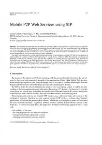
Figure 1: VoIP infrastructure
The attending physician visits a patient in the ICU and observes a condition that she would like to discuss with the patient’s primary physician. The attending doctor directs the communication system to set up an automatic call between the outside physician and herself when he arrives at the hospital. When the primary care physician arrives, the system initiates a call between his phone and the phone in the ICU closest to the attending physician. While talking, the patient’s doctor pulls up related patient lab results and radiology images on his office PC. A little later, the system notifies the attending physician of an impending appointment on her calendar in another room. The notification is delivered as an instant message that appears on the ICU phone. She transfers the ongoing call to her Wi-Fi phone from the ICU phone and continues the conversation while walking to the meeting. During the discussion, she conferences in a technician from the radiology lab so the two doctors can ask for clarification. After finishing the discussion, the attending physician pushes the “save as email” button on her phone, causing the system to transcribe the call and to send the recording and transcript to the attending physician’s email for her records. Finally, the system automatically adds the transcript directly to the electronic medical record for the patient. This single example highlights several desirable features that are not present in current phone systems. First, the system is integrated with location tracking, enabling actions to be triggered when a person is in a certain location or in a location meeting a specified condition. Second, the system can initiate calls between two people and can find the phones or endpoints closest to those people. Third, it supports call pickup from a semi-public phone. Fourth, the system can extend a two party call to a multipoint call, automatically interposing a conference bridge when needed. Fifth, it supports on-demand recording and transcription services. Sixth, the system integrates with other vertical applications in use. Research Objectives: Locate and track unmodified wireless client devices to room-level accuracy with minimal time lag using only low-cost infrastructure. Integrate presence and location services with telephony, email and other communication modes using inexpensive, commodity infrastructure.
Our Solution To facilitate our research, we first built and deployed a complete voice-over-IP (VOIP) system for our office, including desktop phones, outside lines, and voicemail. In keeping with HP corporate strategy, our solution uses open IETF standards that are implemented on off-the-shelf components available at a variety of performance levels and price points. By using standard networking protocols, it can easily be deployed on mainstream computing and networking infrastructure using existing authentication methods. Figure 1 shows our solution, which uses the widely implemented Session Initiation Protocol (SIP) family
of protocols to coordinate voice, video, and instant messaging sessions. SIP [RFC3261] is the IETF protocol for setting up calls between two entities. It is beyond the scope of this paper to fully describe all of the components in Figure 1, but here is an overview: The SIP proxy provides authentication and call routing functions. Each phone or other user agent (UA) registers with the SIP registrar. A registrar provides a level of indirection between a symbolic address of record corresponding to a person and the contact address of that person’s phone or phones. Calls may be placed from desktop phones such as the Cisco 7960 and soft phones running on PC’s or handheld computers. A user may have multiple phones registered, in which case typically all the phones would ring when a call is received so that the user can be reached at any of them. Alternatively, the user can configure the proxy to try his phones sequentially. Once a call has been established between two phones, the actual audio or video is carried by one or more RTP streams. As shown in the figure, additional features are provided by other servers. The media gateway translates between the SIP protocol and the protocol used by the PBX and the public telephone system. In our system, we are using the open source SIP Express Router (SER) [IPTEL] as the SIP proxy and registrar. This proxy supports the invocation of external scripts or executables to provide additional flexibility and extensibility. We use Perl, Python, PHP, and MySQL to implement additional call handling features. Scripting support enables administrators to quickly implement new functionality. The SIP proxies and related telephony application services run on standard rack-mounted 1U servers running the Linux operating system. The SIP phones and servers communicate via conventional switched Ethernet. We are currently using a relatively expensive Cisco media gateway to interface between our SIP system and the lab’s Nortel PBX; however, there are lower cost alternatives available. We worked with the HP IT department to define and implement an HP-corporate approved way for SIPbased voice and video calls to cross the corporate firewall without requiring two factor authentication for in-bound phone calls. All calls between user agents inside the firewall and outside the firewall are routed through an Ingate Siparator [Ingate] proxy that ensures that all media streams are associated with calls that have either been initiated or accepted on internal user agents. In addition, it shields internal user agents from attack from machines on the internet.
Web-based voicemail and transcripts In the system deployed in our lab, voicemail is provided by an application that is part of the Asterisk open-source PBX [Asterisk]. This application is a user agent that registers itself on behalf of each user. From the point of view of the SIP proxy, it looks like a telephone that waits several seconds to answer. When it answers, it records the call to an audio file. As one example of how the system can be augmented by layering applications on top of the off-the-shelf infrastructure, we developed a web interface to voicemail (Figure 2). The original voicemail application provided a touch-tone phone interface to access voicemail. We added PHP pages that authenticate a user and give access to the audio files corresponding to recorded calls, call identification, and call length. In addition, we added a voicemail transcription service by using the speech recognition system from the HP Labs “Speechbot” speech indexing project [Speechbot]. We extended Asterisk to make SOAP calls to the Speechbot service, sending the recorded audio and receiving the transcription in response. The script then stores the transcribed text in the database backing the voicemail web interface. The text of the message is also sent to the user’s email account along with a link to the audio on the voicemail website. In similar fashion, the call transcription service described in the example in the first section could be implemented by scripts on the SIP proxy adding the voicemail application to the call and invoking the transcription service upon completion of the call.
Working Deployment The SIP telephony infrastructure has been running in our facility since May 2003. We use it as a "living
Figure 2: Web voicemail and transcripts
lab" as our day-to-day phone system (approximately 30% of our population uses it exclusively). The system has been very reliable for the most part, though it has highlighted some inadequacies of our production data network. Users of our system have been enthusiastic about having web access to voicemail. Several people requested to be able to use the system based on that feature alone.
Location Tracking Implementation In this section, we describe our solution to location tracking, which is required for integrating location services with communication. We have built tracking solutions for a number of wireless protocols, including IrDA, Bluetooth, and 802.11. This paper will focus on the 802.11 tracking system. A naive approach to finding targets using RF signal strength is to place three scanners in the corners of the building, measure the received signal strength of the target’s transmissions, and calculate the distance of the target to each scanner based on a path-loss model. Unfortunately, in most office environments, this approach doesn’t work. Signal reflections, multipath fading, antenna orientation, fixed obstructions (walls), and moving obstructions (people) preclude a simple (or even monotonic) relationship between signal strength and distance. Angle of arrival or time of arrival methods are more accurate, but are challenged by signal reflection and multipath. In addition, they require non-commodity and hence expensive sensors. They also have difficulty with walls. Signal-strength measurements naturally divide buildings into rooms because the path loss through a wall is significant; angle- or time-based systems locate objects in absolute coordinates which may leave the system confused as to which side of a wall the tracked object is on (is the doctor in the operating room or the staff lounge?). The nonlinear nature of RF in an office building suggests that a large number of very low-cost sensors scattered through the infrastructure and measuring signal strength may be the most effective solution. Such a low-cost, dense network of sensors has been deployed and tested in our office building.
802.11 Sensor network: Hardware and Software Our approach is to deploy a network of 802.11 scanners throughout an office building and measure transmitted signal strengths. The tracking technology is based on established research in RF signal strength analysis (in particular [Bahl]); the implementation has been carefully focused on tracking large numbers of client devices without requiring any special software or hardware on the client. Each scanner consists of a low-cost embedded computer with wired Ethernet and a PCMCIA slot for a commodity 802.11 card. All of the scanners listen to a single 802.11 channel in promiscuous mode and extract core identifying information from each packet received: packet type, received signal strength, signal quality, network identifier, and other distinguishing information. For privacy reasons the content of the packet is
Figure 3: Location-tracking system architecture
dropped. In buildings using access points on multiple RF frequencies, the scanners periodically shift in unison from channel to channel so that they can monitor all of the channels of interest. Periodic channel hopping also enables the scanners to cover both 802.11b/g and 802.11a frequency bands if the system uses 802.11a/b/g cards. The scanners continuously send packet information over the wired network to a data consolidator which records statistics in a SQL database and aligns packets (i.e., decides if a packet has been seen by multiple scanners). The inference engine receives the processed data stream from the consolidator and uses the aggregated information to estimate the position of targets. Tracking data are stored in the SQL database and are accessible via a web interface, SOAP interface, and a SIP location server. We have tried a variety of algorithms for locating targets based on the raw tracking data. The most robust and reliable algorithm to date is the “normalized room signature”. To generate a room signature, a person carries a ‘talkative’ wireless device around each room for a minute or two while the system records the signal strength and quality for each packet received by each scanner. Statistics per scanner are calculated from these data (e.g. minimum, maximum, mean, standard deviation, and skew) for both signal strength and quality. In addition, relative frequency of packet reception by scanner is calculated (nearby scanners see a large percentage of the transmitted packets). A room signature is this set of statistics. In large rooms or rooms with many RF obstructions these statistics may vary strongly by position in the room; in this case the calibration routine automatically divides the room into ‘subrooms’. The inference engine calculates statistics on the packet data gathered from each target at five second intervals and places these in the target’s aggregated statistics queue. Older data are removed from the queue either when they are too old (a few minutes) or when an adequate number of more recent packets have arrived; around 100 transmissions are sufficient to guarantee a good position estimate. The target statistics are normalized and a correlation value is calculated for target data versus the normalized room signature data for each room. The room correlations are rank ordered and a ‘95%’ distance confidence is calculated as the physical distance between rooms with a correlation value within 95% of the best correlation—i.e., if many rooms have roughly the same correlation score, then we have low confidence that the target is actually in the room with the highest correlation score. Finally, the inference engine uses a rule-based approach to decide the reported target room location, taking into account the room correlation, number of packets received, 95% distance confidence, the access point the client is associated with, and the calibration confidence ranges (measures of the attainable accuracy based on the available calibration data). The final position estimate is given as a room, a set of rooms, an approximate location within the building (e.g. ‘southwest corner’), or ‘unknown’.
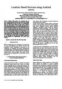
Working Deployment We have deployed 23 802.11b scanners across one floor of a typical office building (approximately 20,000 ft2) in downtown Cambridge, Massachusetts (USA). The density of scanners is non-uniform to test for variation in position estimate based on scanner density. This installation has been in operation since October 2003, with minor interruptions (we have taken it to two conferences). At any one time it is typically tracking 15 wireless clients on the scanning floor and 60 devices from other floors or buildings. The room signature algorithm reliably finds and tracks wireless clients in the building. Tracking lag time for a client is a function of how many packets the client is transmitting. To ensure good location
Figure 4: Scanner locations (left), and snapshot of live targets being tracked (right). The 8 blue boxed targets have been located to a single room; the 2 targets in green have approximate locations. The 7 red “RA2000-#” targets are access points. Another 43 targets (not shown) have been identified as being outside of this building.
estimates, quiescent clients are located with an ICMP ‘ping’ every 150 seconds. Busier clients (10-20 packets per second) easily attain the system’s minimum lag time of 10 seconds.
Tracking Accuracy The running system finds the approximately location of all clients—but the accuracy varies depending on the density of scanners and the indoor ‘terrain’. Tracking accuracy (finding the client in the correct room) has a number of sources of intrinsic error that limit performance. The indoor environment is a complicated maze of RF null zones and shadowy reflections. The RF characteristics of a building vary as people move around and devices use the RF spectrum. Each client device has its own unique RF characteristics based on its particular transceiver, firmware, and (most importantly) antenna orientation and mounting. If the client is moving within the room (like a doctor visiting a patient), the RF problems tend to be averaged out. But if the client is fixed (the doctor put her laptop on a table), a bad RF spot can potentially throw off the tracking system. These sources of errors can be mitigated with clever algorithms; e.g., Bayesian analysis of room connectivity or Kalman filters that take into account that characteristics of the received data. But fundamentally, a higher scanner density is the best guarantee of better position accuracy. We’ve run experimental trials to try to determine the required scanner density for different office environments, as shown in table 1. For example, the measured data suggest that in an office environment with 100 ft2 offices, a scanner density of approximately 1 per 550 ft2 should be sufficient to locate people to within an office with 95% accuracy. Table 1: Measured 95% tracking accuracy.
Open space (cubicles/corridors) Enclosed rooms (offices with walls)
Scanner density 1 per 600 ft2 1 per 1600 ft2 190 ft2 270 ft2 2 105 ft 200 ft2
It can be difficult to optimally position the scanners. The data gathered during calibration and operation can be used to optimize the scanner placement. There are two ways to optimize: micro-position and macro-position. A scanner positioned poorly inside a room may experience unusually high RF multipath or null-zones. This can be detected by examining the range and deviation of the RF signal strengths received by the scanner. Poorly positioned scanners can be improved by moving them a foot or two.. Macro-position optimization uses sensitivity analysis to calculate how much each individual scanner is
contributing to tracking accuracy. Regions with low tracking accuracy benefit from additional scanners. Scanners that are not improving tracking accuracy are relocated to regions that need the higher accuracy. At the present this macro-position optimization is more art than science—one of our ongoing research activities is developing tools to make it easier to optimize scanner macro-position. A correlate of this research activity is the optimization of the position of access points.
Competitive Location Tracking Approaches There are several competitive commercial tracking systems available, based on either measured signal strength or time of arrival. Measured signal strength solutions take two forms: (1) modified 802.11 access points that record signal strength or (2) custom client software that is installed on each client device that is to be tracked. In both cases, position is estimated using tracking filters and some form of proprietary room signature algorithm. Performance data for measured signal strength systems are hard to judge (companies are unwilling to provide hard data), but we believe that they perform at best comparably to our system, and at worst, where access point density is low and the number of channels in use is high, they will have great difficulty tracking clients. As location tracking is adopted by the major wireless network infrastructure providers as a standard feature, we believe these companies will exit the market. A few companies have built time-of-arrival (TOA) tracking systems; they require that at least three custom sensors receive the same packet from a target, then generate a position estimate based on the relative (nanosecond accuracy) arrival time at each sensor and the known sensor locations. They report accuracy on the order of 1-3 meters with a 10 second lag time to locate the target. Earlier in this paper we describe the advantages and disadvantages of TOA tracking systems (both financial and technical). Another potential problem with TOA systems is that we believe that over time the cell size of 802.11 access points will shrink to accommodate a higher client density. Small-cell clients will broadcast at lower power levels, necessitating more TOA receivers. But our low-cost, high density sensor network actually benefits from the lower transmission power as it helps to isolate the client locations.
Integrating presence and location services In order to integrate location services with communication, we developed a Presence and Location (PAL) Service as an add-on to SER. Presence indicates whether a user is available to talk, with values such as online, busy, or offline. Location tells where a user is, with values such as “CRL Room 12-128”. Presence and location information in SIP is distributed by a publish/subscribe/notify model [RFC3265]. The PAL server aggregates presence and location data published via phones, instant messaging clients, and the location tracking system. Watchers (user agents) that wish to receive presence or location information subscribe to a user’s address of record. If the user is authorized to subscribe to another user’s presence attributes, then PAL sends notification messages to the watcher. Our location tracking system uses the registration information from the SIP proxy to identify the user associated with each wireless client. The tracking system publishes location information to the PAL server when it detects a change of location of a user’s 802.11 client. We also defined and implemented a location event package, which provides per location information rather than per person information. For example, a watcher would subscribe SIP address sip:
[email protected] to learn which users are in office 12.128 at CRL. The system may be configured to restrict access to this information to individuals who are either in that region of the building or who have appropriate privileges. The PAL server that we developed enables the implementation of the location services described in the extended example in the first section of this paper. Because of the flexibility of SIP, services may be added either by augmenting user agents or infrastructure. Consider the portion of the example where a call is set up between the ICU physician and the outside physician (when the attending arrives at the hospital). In a user-agent based implementation, the attending physician’s phone subscribes to the outside doctor’s presence information. When her phone receives a notification saying that the doctor is in the hospital, it places a call to the doctor’s address of record, which causes his Wi-Fi phone to ring.
Alternatively, in a server-based implementation, when the system detects that the outside physician has arrived at the hospital, the system uses third party call control [RFC3725] to initiate a call from the ICU physician’s active phone to the outside physician’s phone.
Presence and Location Service Trials We are actively participating in the Internet2 Presence and Integrated Communication [PIC] working group. We deployed our location tracking system and PAL server as part of PIC working group “rich presence trials” at the January 2004 Internet2 JointTechs meeting. Participants in the trial could view the location of other users on a web portal, send instant messages, make phone calls via SIP, and could view the presence status and locations of their colleagues on their buddy list. Approximately 300 laptop computers were tracked during the four day meeting; a smaller number of people participated in the PIC trial. During this trial, we ran into some incompatibilities between the network infrastructure and our location tracking system. We had been relying on the ARP protocol to map 802.11 MAC addresses to IP address, but the switch that performed MAC-based access control prevented the use of ARP on half of the floors. In the laboratory, we used client association data gathered from the access points via SNMP to improve location tracking estimates. The JointTechs meeting used five different models of access points with a variety of SNMP interfaces (including ‘non-functioning’) and a switch that blocked SNMP. As a result, we were unable to use access point association data as input to the location tracking system. We deployed an improved version of the system at the Internet2 Spring member meeting in April 2004. We improved the system to overcome the two main deficiencies of the system from the JointTechs meeting. We updated the scanners to gather the MAC address to IP address mapping by observing the MAC and IP addresses in monitored packets. In addition, the scanners parsed 802.11 link management packets and observed source and destination MAC addresses to learn which wireless devices were access points on the SSID of interest and which clients were associated with those access points. Not only did this technique find the known access points, it was also able to identify “rogue” access points. These rogues were typically notebook computers inadvertently configured in ad-hoc mode or ‘internet connection sharing’ mode—both of which can snare nearby wireless users and cause great confusion. At the Spring Internet2 meeting, we tracked the wireless devices of all 500 attendees, though we only had user identification for the 60 attendees who authenticated to the system with a SIP user agent. The location information gathered by the system was displayed in several ways. Attendees could use a web browser to see a map of the hotel annotated with the location of devices identified by IP address. Figure 5 shows snapshot of a typical view of that map during the meeting. Attendees could also see a second map with the location of users who identified themselves to the system via SIP authentication. Attendees who used the sipc SIP client from Columbia University were able to see the location of their buddies in both a list and a map view. Figure 6 shows an example screenshot of sipc displaying the location of three users. At both conference deployments we have been pleased by the positive reception from attendees and IT staff. The attendees have been delighted with the ability to find and communicate with their colleagues. The IT staff became enthusiastic when they found it helped them do their job. For example, at the Spring Internet2 meeting, the IT staff using a packet scanner identified a mobile user with a virus-infected laptop that was attacking other machines. They turned to the location-tracking system to map the client MAC address into a room location, walked downstairs, and solved the problem with a brief conversation with the attendee.
Status and next steps Both the SIP telephony infrastructure and wireless location tracking system are in continuous operation in our facility. We continue to extend these technologies to add services, improve reliability, and provide better management tools. Our current VOIP activities include collaborating with MIT to incorporate the MIT Galaxy speech
Figure 5: Typical live tracking data at Internet2 Spring meeting. The left figure shows the three floors of the Marriott Crystal Gateway hotel where meetings were held. Targets are identified by their IP address (if available) or MAC address. The right figure shows the positions and status of scanners in the building.
interaction system as a way to access information, to leave voicemail, and to configure user preferences. We are also working with HP IT and HP telecommunications to interconnect HP facilities with voice and video over IP. We continue to actively participate in the Internet2 Presence and Integrated Communication working group. The goal of this group is to deploy systems like ours at all of the Internet2 member institutions systems. For our next demonstration we hope to extend our presence and calendar-based services to include session reminders (the session starts in 10 minutes and you’re not in the room), live maps that combine location tracking data with event information (the Health care group is in Room X and your colleagues are already there), and network utilization data. We are testing different location tracking algorithms and methods of making the location-tracking infrastructure more reliable, robust, and faster to deploy. We are building a ‘rapid deployment’ system
Figure 6: Columbia University’s sipc user agent showing location in contact list and buddies on map.
which will use ad-hoc 802.11a networking with auto-calibration capabilities and should eliminate the requirement that all scanners be attached to the wired network (stringing cables is a limiting factor for rapid deployment). We believe that the system that we described is a good fit for HP’s server, infrastructure, and networking equipment businesses. This infrastructure should interface to all standards-compliant software and hardware user agents to provide maximal flexibility to our customers while still minimizing costs. The infrastructure and applications can be integrated with OpenView for manageability. Deploying customized features and applications is a good opportunity for HP Services.
References [Asterisk] [Galaxy] [INGATE] [IPTEL] [PIC] [Bahl] [RFC3261] [RFC3265] [RFC3725] [Speechbot]
Asterisk Open Source PBX. http://www.asterisk.org/ MIT Galaxy spoken language system. http://www.sls.csail.mit.edu/GALAXY.html Ingate SIParator SIP proxy. http://www.ingate.com/siparators.php SIP Express Router (SER). http://www.iptel.org/ser/ Presence and Integrated Communications (PIC) Working Group. http://pic.internet2.edu/ RADAR: An In-Building RF-based User Location and Tracking System. P. Bahl, V. Padmanabhan. INFOCOM 2000. SIP: Session Initiation Protocol. J. Rosenberg, H. Schulzrinne, G. Camarillo, A. Johnston, J. Peterson, R. Sparks, M. Handley, and E. Schooler. IETF. June 2002. Session Initiation Protocol (SIP)-Specific Event Notification. A. B. Roach. Best Current Practices for Third Party Call Control (3pcc) in the Session Initiation Protocol (SIP). J. Rosenberg, J. Peterson, H. Schulzrinne, G. Camarillo. Speechbot. http://www.speechbot.com