Today, a variety of multi-agent systems provide means for facilitating the imple- mentation of such systems, ..... notified, and the auctioneer waits for the bidder to transfer the money. When the ... the auction from its data store. The full process ...
Integrating Process Modelling into Multi-Agent System Engineering Tobias K¨ uster, Marco L¨ utzenberger, Axel Heßler, and Benjamin Hirsch {tobias.kuester|marco.luetzenberger| axel.hessler|benjamin.hirsch}@dai-labor.de DAI-Labor, Technische Universit¨ at Berlin, Germany
Abstract. While today’s agent oriented software engineering facilitates the development of complex, distributed systems, fundamental problems remain. One of the difficulties is that one can see only part of the system, or one side of the business, but not the whole context. BPMN is considered a remedy here, but while suitable for modelling some aspects of agenthood, there are others for which BPMN does not go very well. In this paper, we show how BPMN can be embedded in a broader methodology so that its strengths can be exploited while avoiding its weaknesses.
1
Introduction
The design of large, distributed applications involving several communicating partners can be extremely challenging. Besides the prevailing SOA solutions, agent-oriented systems are regarded as a promising approach in this domain [1]. Today, a variety of multi-agent systems provide means for facilitating the implementation of such systems, such as libraries and special languages for discovery, messaging, and event handling, and some provide advanced concepts like proactiveness and autonomy. However, some general problems of distributed systems remain, such as the alignment of sending and receiving messages in a complex communication protocol. The developer sees just a part of the problem: One file of source code, one agent’s set of rules, one side of the communication. What is needed is a holistic, integrated view on the system, showing the involved partners and their processes as they are orchestrated in the system. Additionally, everything has to be welldocumented, especially in cross-enterprise projects, and technological progress is demanding shorter and shorter development cycles. One possible solution to this problem is the application of techniques from business process design to agent engineering. Over the last years, a number of industrial projects have investigated business process design as a way of closing the gap between analysis and development [2]. Many ideas from agent theory, such as roles, rules, and communication, can be found in the Business Process Modeling Notation (BPMN), too, which has already led to some efforts of mapping BPMN diagrams to multi-agent systems, as we will see later. We will have a closer look on BPMN in Section 2.
Still, there are other aspects, for which BPMN is not intended, such as organisation, data, or complex algorithms. While BPMN describes business partners, i.e. roles, it does not define how these are implemented by agents, let alone their physical location. And while process diagrams are in general very well suited for displaying all kinds of control flow, modelling each single algorithm in BPMN would not be adequate. Finally, while BPMN can refer to data types, e.g. for properties and assignments, it does not provide means for defining them. In order to apply business process design in agent engineering, it needs to be combined with other techniques and additional notations. Therefore, in Section 3, we introduce a methodology, in which BPMN is used together with ontology engineering, multi-agent system design and service engineering, combining the strengths and balancing the weaknesses of the individual approaches. While the methodology is applicable for other agent frameworks, too, we will illustrate it using the JIAC framework, providing a number of useful tools and editors (see Section 4). Later, in Section 5, we will apply the methodology to a simple online auction example, before we take a look at related work and conclude.
2
BPMN
The Business Process Modeling Notation [3] can be seen as a combination of UML’s Activity Diagrams and Sequence Diagrams. It can be understood at three levels of abstraction: 1. The diagrams are made up of a few easily recognisable node types, i.e. Events, Activities and Gateways, connected by control- and message flow. 2. These basic elements are further distinguished using sets of marker icons, e.g. Message, Timer, and Error Events, or parallel and exclusive Gateways. 3. Each element contains a number of additional attributes, which are hidden from the diagram, but contain all the information that is necessary for automated code generation. Thus, BPMN is easily understandable by all business partners, even those who have great knowledge in their domain but do not know too much about programming and multi-agent systems. At the same time, BPMN diagrams provide enough information for generating executable program code from them. One problem with BPMN which is often brought up is that most of the semantics are derived from the mapping from BPMN to the Business Process Execution Language (BPEL), so for those elements that are not covered by this mapping the semantics are not always made clear, let alone formally defined. Still there is an increasing number of approaches describing the semantics of BPMN using e.g. Petri nets [4–6], and version 2.0 of the specification makes things clearer, too. But why not use Petri nets in the first place? The answer is simple: While Petri nets have very clear semantics, and basically everything can be expressed as a Petri net, some high-level constructs, that are directly supported by BPMN, would result in huge, incomprehensible Petri nets.
BPMN diagrams, on the other hand, have a variety of notational elements, making them well suited for the design of distributed systems in general and multi-agent systems in particular. The process diagrams are subdivided in pools, each representing one participant in the process, which maps to the concept of agent roles. Using message flows for communication between pools, even complex interaction protocols can be modeled clearly. The “ad-hoc” process even resembles goal-oriented behaviour. Further, the notation supports features such as event- and error handling, compensation and transactions. But as already mentioned, there are other aspects of a system that can not be designed very well using BPMN alone. We will focus on these issues and how to deal with it in the next section.
3
Methodology for Process Oriented Agent Engineering
The core aspect of our approach is the application of business process design in an early stage of the development process in order to provide a holistic view of the entire distributed multi-agent system. As we have pointed out, BPMN alone is not sufficient for this task, but has to be embedded in a methodology that deals with the missing aspects, including (a) the declaration of data types, (b) design of agent organisation and distribution, and (c) textual programming for low-level algorithms. Further, as one BPMN diagram shows only one business process, while a complex system might consist of a number of processes, we also include (d) use case diagrams, providing an overview of the processes belonging to the system and their relation to the several participants. Finally, no methodology can be complete without iterative development, testing and maintenance.
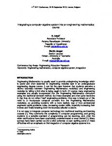
Fig. 1. Process diagram showing the stages emphasised in this work within the complete methodology.
The “big picture” is shown in Fig. 1: The development process starts with use case analysis and ontology engineering. Then, for each use case a business process diagram is created. From the processes, the role model and a number of behaviours/capabilities are derived. Both are then further refined using tools more suitable for this task than BPMN. Finally, the agent organisation model
and the components are integrated and tested, and the process can go into another iteration, until the system is eventually deployed. In the following, we will describe the relevant steps in more detail. 3.1
Use Case Analysis and Ontologies
The methodology starts with the identification of actors and use cases of the system under design. For this task we adopted the use case notation from UML. Here, each actor represents an agent role, with each use case being a business process in which the actor takes part. Apart from providing an entry point into the design, this also serves as a connection between the several business process diagrams, since one BPMN diagram alone does not suffice for describing a complete system.1 Another task that can and should be accomplished in this early phase is the (formal) definition of the domain vocabulary or ontology. However, in the context of this methodology it is not relevant whether this is done using UML class diagrams, Java classes, or sophisticated ontology languages, such as OWL. 3.2
Business Process Engineering
Next, a number of BPMN diagrams are created based on the use case diagrams. Each use case corresponds to one business process, and each actor involved in the use case matches one pool in that process diagram. Here, the process diagrams are not used for modelling the entire life cycle of that actor. Instead, they depict only the workflow and the communication between the actors for this specific use case. In this regard they can be seen as a combination of activity diagrams and protocol diagrams. The process diagrams will serve as starting point for the implementation. As a rule of thumb, the process diagrams should contain at least each activity and each branch related to the communication with the other actors, referred to as the ‘public process’ in the BPMN specification [3]. The payload of the messages should also be specified using the formerly defined domain model. Of course, the diagrams can be further detailed to contain more of the actor’s internal activities (the ‘private process’), since they can also be used as documentation and for validating the final implementations against them. But as the diagrams’ complexity quickly increases as one tries to depict each detail of an algorithm, the modeler has to find an adequate compromise here. For example, while possible, it does not seem reasonable to detail a path finding algorithm like A∗ in BPMN; instead, a single activity called ‘calculate path’ should be used. 3.3
From Business Process to Multi-Agent System
The business process diagrams provide a view on the system as a whole that can be used as groundwork for the following implementation of (a) the agents’ 1
Version 2.0 of BPMN includes Conversation Diagrams, serving a similar purpose. We still prefer use case diagrams, as these are more intuitive to understand.
behaviour, e.g. in the form of plans, rules, or services, and (b) the organisational model, e.g. roles, agents, and agent platforms. Of course, the derivation of agent behaviours from the process diagrams is highly dependent on how behaviours are implemented for a given agent framework, e.g. imperative or declarative, as a set of rules, goal-oriented, or as hybrid approaches, and whether it is done automatically or manually. Generally speaking, for each pool in the different process diagrams, or more precisely, for each start event in the pools, one behaviour is derived, covering the workflow (branching, communication, etc.) from that starting point on. For instance, a pool with a message start event can be translated to a script for the content of the workflow and a rule for starting that script when the given message arrives. The basic procedure of the mapping has been developed in our previous work. First, a BPMN normal form for facilitating the mapping has been investigated and formalised using Petri nets [5]. Then, the first steps of the actual mapping were specified, basically mapping pools to agents, processes and flow objects to the agents plans and the control flow, and message flow to the exchange of messages between the agents [7]. Since then, the mapping has been adapted in order to provide better support for systems consisting of multiple BPMN diagrams, by taking the use case diagrams into account, too. The use cases and actors are used for identifying the agent roles. For each actor one agent role is defined, offering the respective behaviours derived from the processes corresponding to that use case. Since the business process diagrams make no assertions towards the grouping of roles to individual agents and agent systems, this aspect has to be dealt with in the next step. Fig. 2 shows an overview of the models and their dependencies. Both parts of the transformation can be done manually or automatically. We will introduce a BPMN editor that can be used for automatically generating services and a role model for the JIAC framework in Section 4.1. 3.4
Refinement
By now we have agent roles and their relation to a number of behaviours, derived from the use cases, and the behaviours implementing the workflow and the communication as designed in the BPMN diagrams. As mentioned, the use of BPMN is not efficient when going into too much detail. Thus, in this step the behaviours are refined with everything that is too cumbersome to model in BPMN, e.g. complex calculations, or GUI calls. Further, the role model has to be completed with actual agents and agent platforms. 3.5
Integration, Testing, Deployment
After the different parts have been integrated, the system needs to be tested. Here, the process design can be of some help, too, as processes can be simulated, similar to a Petri net, and the behaviour of the final system can be compared to that of the process. Most notably, the use of model driven engineering ensures
Fig. 2. Overview of models and their dependencies. Use Cases, Process Model, Role Model, Implementation
the consistency of the resulting multi-agent system with the formerly defined models. Depending on the applied tools, the system (or at least parts of it) can be generated from the models, and the models can be updated according to the implementation. However, the latter is still a hot topic of current research.
4
The JIAC V Agent Framework and Tools
While our methodology is independent from any specific agent framework, it highly benefits from model driven engineering, thus a certain amount of tool support should be provided, so that the mapping from the process models to the implementation can be automated. In this section we will have a look at the JIAC framework, which satisfies this requirement. JIAC V is a Java based multi-agent development framework and runtime environment [8]. JIAC combines agent technology with a service oriented approach and accentuates this facet by its scripting language JADL++. Furthermore, the framework features transparent distribution of agents and services, semantic service descriptions (based on ontologies), agent management, and provides support for dynamic reconfiguration in distributed environments, such as component exchange at runtime and strong migration. JIAC V agents can be programmed using plain Java or JADL++. Using Java, the agents’ behaviour is defined in a number of so-called agent beans, which are controlled by the agent’s life cycle. While agent beans are required for some sorts of behaviour, e.g. for displaying a GUI, or perceiving or acting in non-agent environments, other aspects, such as memory access, or messaging, can be abstracted using JADL++. The language features knowledge, or facts,
based on the ontology language OWL as well as an imperative scripting part that is used for the implementation of services, including high level language features such as parallelism, events, and many more. JIAC comes with a set of tools, supporting development from the analysis to the deployment of multi-agent applications. The most important tools regarding our methodology are introduced in the next sections. 4.1
The Visual Service Design Tool
Our methodology starts with defining use cases and the respective BPMN processes. This stage is supported by the Visual Service Design Tool (VSDT) [9], a BPMN editor, providing process analysis and validation tools, such as a process structure view, a process simulator, and the generation of natural language process documentation (see Fig. 3). The VSDT is also used for creating the use case diagrams, establishing the relation of participants to processes and connecting the individual business process diagrams to a complete system. The VSDT includes an extensible transformation framework, which is responsible for grouping the nodes of the process graphs to blocks of structured programming languages (i.e. sequences, selections, and repetitions). Currently, the process diagrams can be exported to both BPEL and to JIAC’s scripting language JADL++, and more transformations can easily be added. The use case diagrams are translated to the agent role model and the relation of the roles to the generated services. These models then serve as input for the Agent World Editor.
Fig. 3. The Visual Service Design Tool
4.2
The Agent World Editor
The MAS Design in JIAC is done with the Agent World Editor (AWE) [10]. AWE allows for the visual creation and editing of multi-agent systems via drag and drop and supports concepts such as agent-nodes, -types and -roles or components. The applied notation is simple but comprehensive and represents the entire MAS in one single diagram as directed graph (see Fig. 4). Access to the file system allows to reference existing agent beans or JADL services just like the ones created by the VSDT. A code generation feature allows for the generation of executable code from the visual MAS design. The code can be understood directly by the JIAC runtime and triggers the execution of a MAS according to the design specification.
Fig. 4. Agent World Editor and JADLedit as a part of JIAC’s tool suite.
4.3
JADLedit
JADLedit [11] is a source code editor for JADL++. The tool facilitates the development of JIAC services with features such as syntax highlighting, code completion, and error marking (Fig. 4). Regarding the methodology, JADLedit is used for the implementation of previously generated service stubs. As stated above, JADL++ services are using OWL as representation for complex data types. Thus, JADLedit allows for type safe editing of knowledge (facts). For this purpose JADLedit includes an ontology browser view, which can be used for browsing existing OWL ontologies, providing a visual representation of their classes and properties.
5
Example
In this Section we demonstrate how our methodology is applied using the example of a simple English online auction scenario. First, the use cases are identified using the VSDT. In our example we have the use cases Create Auction, Place Bid and Close Auction, which are performed by the actors Auctioneer, Seller and Bidder. The next step is ontology engineering. We have categories such as Seller and Bidder, holding e.g. their nickname, rating, and contact information, as well as categories like Auction and Bid. However, we will not go into more detail here and fast-forward to the process engineering instead. Each use case corresponds to a business process, and modelling these is the main task of the VSDT. Close Auction is the most interesting, so we will have a closer look at it. Each of the actors involved in the use case corresponds to a pool: Auctioneer, Bidder, and Seller. The auctioneer starts the process when the time of the auction is over. He acts as trustee between seller and bidder, which are more or less just reacting to him. In case there are no bids at all, the seller is notified and the process terminates. Otherwise, both the seller and the awarded bidder are notified, and the auctioneer waits for the bidder to transfer the money. When the bidder informs the auctioneer that the money has been transferred, the auctioneer notifies the seller, who then ships the goods and informs the auctioneer. The auctioneer then transfers the bidder’s money to the seller and finally removes the auction from its data store. The full process can be seen in Fig. 5. While this diagram shows more than just the “happy path”, there are surely many more exceptions and what-ifs needed for a real auction, but for a small example this will do.
Fig. 5. BPMN diagram for use case Close Auction
Next, the process has to be enriched with non-graphical elements and attributes, using the categories defined in the ontology, such as the messages sent, assignments made, and expressions used in branching conditions. While the VSDT does provide means for assisting this task, e.g. basic validation for assignment expressions and conditions, it is still relatively laborious, and we are currently investigating ways to simplify this part. Next, the VSDT’s export feature is used to generate agent roles and JADL services from the BPMN diagrams, which are then detailed further using AWE and JADLedit. We enrich the role model with additional roles and components needed for the example, aggregate the roles to agents and place these agents on agent nodes. In our example, we have one auctioneer agent and some agents implementing the roles of both, seller and bidder, all situated on one node, as depicted in Fig. 6.
Fig. 6. Left: Use Case diagram. Right: Agent World Diagram. The framed portion has been generated from the use case and process diagrams.
Note that while for each actor one role has been created, there are more components (in this case: JADL services) that there were use cases. For each pool (i.e. each actor participating in a given use case) one service is created, which is reflected as a component in the agent world diagram. For the seller’s pool in the above diagram, a total of three services has been created, so we will take a closer look at this one now. The seller’s part of the Close Auction process begins with either receiving a message telling him that his item has been sold, or receiving a message telling him that no sale was made. This results in two JADL services being generated for the seller. Further, as the ‘sold’ case can merge into the ‘not sold’ case if the bidder does not respond to the payment request, a third service is created, the common part of both services, which is called at the end of each of the former. Making things further complicated, the process does not have proper block structure, which is required for most programming languages, including JADL++.
Thus, the activity dismiss auction is duplicated and moved to the end of the two branches, just before the merging gateway. 2 Thus, the seemingly simple seller process results in three interacting services with some shared logic. The generated JADL services, holding the necessary communication with the business partners and the basic branches and decisions, can now be further refined and extended using the JADLedit source code editor.
6
Related Work
For our work, we evaluated a number of similar approaches which combine process modelling with agent technology. The Agent-oriented Development Methodology (ADEM) [12] uses a combination of business processes and agent-oriented models for the overall software engineering, while the agent model is developed by using the Agent Modeling Language (AML) [13], an extension to the UML 2 notation. GO-BPMN (goal oriented BPMN) is used for describing agent systems based on processes and the goals they fulfil [14]. This seems like double work done by the modeller as they use goals as finite states of the processes (see for example [15]). In our approach, we use domain ontologies to capture, analyse and model the “what”. When using process modelling, we are more interested in capturing the idea and the expertise of a domain expert of “how” things are done or should be done, also through different levels of abstraction. The “how” is modelled in a process diagram, which can be directly executed by the VSDT. They are also transformed to a JADL script and can be directly executed by JIAC agents. We have chosen the transformation approach here, because process models are not the only source for JIAC-based applications (see also [16, 17]). So the runtime environment is the integration point for heterogeneous design methods. The Prometheus Methodology [18] also integrates the advantages of process orientation into the agent-oriented software development. The Methodology comprises the three main topics System Specification, Architectural Design, and Detailed Design, and provides MAS development on the basis of several different diagrams. Prometheus applies processes for the detailed design of each single agent type. For the specification of these processes, an extension to the UML activity diagram notation is used. At this point, Cheong and Winikoff have shown in [19] how Prometheus can easily be improved by different methods. They have used Hermes [20] here to improve the design process regarding agent interactions, which is exactly the domain of BPMN, only for business processes. Like Prometheus, the Gaia Methodology [21] has been designed to provide formally guided and comfortable MAS development. The methodology structures itself into Analysis, Architectural Design and Detailed Design. Each phase comprises the creation of various diagrams, each one highlighting particular aspects of the MAS. In comparison with other methodologies, Gaia exceedingly attends to organisational abstractions, with a particular focus on organisational 2
As a result, the third service, holding the common part, is in fact empty.
rules and -structure issues. Gaia is not intended to commit to the adoption of a specific notation. With regard to the organisational structure, other notations can be adopted to describe and represent roles and their interactions. A respective appliance of AUML is described by Bauer et al. [22]. Klaus Fischer and his research team at DFKI is working on the DSML4MAS Development Environment (DDE), a visual IDE for Jade [23] based on the PIM4Agents metamodel [24]. While they use processes for modelling agent plans, too, they use their own simple notation. One feature of DDE which is still missing in the JIAC tools is that of ‘protected regions’ in the generated code, in which the code can be manually edited and will not be overwritten on code regeneration. WADE is an extension to JADE, using XPDL [25] for modelling workflows, which are translated to Java classes, where each activity is reflected in a method stub [26]. A nice effect of this approach is that workflows can inherit from each other, and that the control flow of the workflow can be revisited without conflicting with the manually written code. The Tropos methodology [27] is model-driven approach to agent-oriented software engineering and consists of a visual notation combined with guidelines for five development phases. It provides strong features for requirements analysis bases on the notions of actor, goal, plan, resource and dependency. For design activities it is combined with features from other software modelling techniques such as UML sequence and activity diagrams together with extension from AUML [28] or it inherits notions from the agent framework that is used to implement the multi-agent system such as Jadex [29]. While Tropos is very strong in analysing requirements we prefer the vocabulary and expressiveness of BPMN for capturing and modelling the procedural knowledge of how thing are done or ought to be done.
7
Conclusion
While agent-oriented software engineering is very useful for creating large, distributed systems, it can still be difficult to design those systems so that the individual parts fit together. A solution to this problem is to provide a view of the entire system, especially during the earlier development stages. In this paper, we make a case for a methodology combining agent-oriented software engineering with business process design using the Business Process Modeling Notation (BPMN). Many aspects of agents are found in BPMN, too, such as roles and communication, making it very suitable for modelling these parts of multi-agent systems. Still, using BPMN for a complete multi-agent systems is not practical, thus our methodology does not rely on business process modelling alone, but also includes the declaration of use cases and data types, the design of agent organisation and distribution, and traditional programming. While the methodology itself is not bound to a specific agent framework, it highly benefits from model driven engineering, so a certain amount of tool sup-
port should be provided. Therefore, we illustrated the methodology by modelling a simple online auction scenario using the JIAC framework and its tools. Of course, there are limitations to visual, process oriented design of agent systems. While the unstructuredness presented in our example could be resolved, there are process diagrams which can not be structured as well [30]. Further, additional research is needed on how the dynamic aspects of multi-agent systems – goals and planning – can best be integrated in the more rigid structures of a business process, for example by extending the concept of the ad-hoc process. Still, we believe that the example also shows the benefits of our approach, as the complex control flow and communication between the involved partners can be visualised intuitively using BPMN. Thus we recommend using process design for a high level of abstraction and traditional agent oriented programming techniques for the details.
References 1. Luck, M., McBurney, P., Shehory, O., Willmott, S.: Agent Technology: Computing as Interaction (A Roadmap for Agent Based Computing). AgentLink (2005) 2. Garretson, P., Harmon, P.: How Boeing A&T manages business processes. Whitepaper, BPTrends (November 2005) 3. Object Management Group: Business Process Modeling Notation, V1.1. Final Adopted Specification formal/2008-01-17, OMG (January 2008) http://www.omg. org/spec/BPMN/1.1/PDF. 4. Dijkman, R.M., Dumas, M., Ouyang, C.: Formal semantics and analysis of BPMN process models using Petri nets 5. Endert, H., Hirsch, B., K¨ uster, T., Albayrak, S.: Towards a mapping from BPMN to agents. In Huang, J., Kowalczyk, R., Maamar, Z., Martin, D., M¨ uller, I., Stoutenburg, S., Sycara, K.P., eds.: Service-Oriented Computing: Agents, Semantics, and Engineering. Volume 4505 of LNCS., Springer Berlin / Heidelberg (2007) 92–106 6. Raedts, I., Petkovic, M., Usenko, Y.S., van der Werf, J.M.E.M., Groote, J.F., Somers, L.J.: Transformation of BPMN models for behaviour analysis. In Augusto, J.C., Barjis, J., Ultes-Nitsche, U., eds.: MSVVEIS, INSTICC PRESS (2007) 126– 137 7. Endert, H., K¨ uster, T., Hirsch, B., Albayrak, S.: Mapping BPMN to agents: An analysis. In Baldoni, M., Baroglio, C., Mascardi, V., eds.: Agents, Web-Services, and Ontologies Integrated Methodologies. (2007) 43–58 8. Hirsch, B., Konnerth, T., Heßler, A.: Merging Agents and Services — the JIAC Agent Platform. In Bordini, R.H., Dastani, M., Dix, J., El Fallah Seghrouchni, A., eds.: Multi-Agent Programming: Languages, Tools and Applications. Springer (2009) 159–185 9. K¨ uster, T., Heßler, A.: Towards transformations from BPMN to heterogeneous systems. In Mecella, M., Yang, J., eds.: BPM2008 Workshop Proceedings. (2008) 10. L¨ utzenberger, M., K¨ uster, T., Heßler, A., Hirsch, B.: Unifying JIAC agent development with AWE. In: Proceedings of the Seventh German Conference on Multiagent System Technologies, Hamburg, Germany, Springer (2009) 11. Burkhardt, M., L¨ utzenberger, M., Masuch, N.: Towards Toolipse 2. Tool Support for the Next Generation Agent Framework. Computing and Information Systems Journal 13(3) (October 2009) 21–28
12. Cervenka, R., Trencansky, I.: Agent-Oriented Development Methodology (ADEM). Technical report, Whitestein Technologies (February 2005) 13. Cervenka, R., Trencansky, I.: The Agent Modeling Language — AML. A Comprehensive Approach to Modeling Multi-Agent Systems. Whitestein Series in Software Agent Technologies and Autonomic Computing. Birkh¨ auser Basel (2007) 14. Burmeister, B., Arnold, M., Copaciu, F., Rimassa, G.: BDI-Agents for Agile GoalOriented Business Processes. In: Proceedings of the Seventh International Conference on Autonomous Agents and Multiagent Systems (AAMAS 2008), Richland, SC, International Foundation for Autonomous Agents and Multiagent Systems (2008) 37–44 15. Whitestein Technologies: Cost Assessment of Risk-sensitive Banking Processes with the Living Systems Process Suite (2009) 16. Thiele, A., Kaiser, S., Konnerth, T., Hirsch, B.: MAMS service framework. In Kowalczyk, R., Vo, Q.B., Maamar, Z., Huhns, M., eds.: Service-Oriented Computing: Agents , Semantics, and Engineering: AAMAS 2009 International Workshop, SOCASE 2009, Budapest, Hungary, May 11, 2009, Revised Selected Papers. Springer (2009) 17. Hessler, A., K¨ uster, T., Niemann, O., Sljivar, A., Matallaoui, A.: Cows and Fences: JIAC V - AC09 Team Description. In Dix, J., Fisher, M., Nov´ ak, P., eds.: Proceedings of the 10th International Workshop on Computational Logic in Multi-Agent Systems 2009. Volume IfI-09-08 of IfI Technical Report Series., Clausthal University of Technology (2009) 18. Winikoff, M., Padgham, L.: Developing Intelligent Agent Systems: A Practical Guide. Wiley and Sons (2004) 19. Cheong, C., , Winikoff, M.: Improving Flexibility and Robustness in Agent Interactions: Extending Prometheus with Hermes. In Garcia, A., Choren, R., Lucena, C., Giorgini, P., Holvoet, T., Romanovsky, A., eds.: Software Engineering for MultiAgent Systems IV: Research Issues and Practical Applications. Volume 3914 of Lecture Notes in Computer Science., Springer Berlin/Heidelberg (2006) 20. Cheong, C., Winikoff, M.: Hermes: Implementing Goal-Oriented Agent Interactions. In Carbonell, J.G., Siekmann, J., eds.: Programming Multi-Agent Systems. Third International Workshop, ProMAS 2005, Utrecht, The Netherlands, July 26, 2005, Revised and Invited Papers. Number 3862 in Lecture Notes in Artificial Intelligence, Springer Berlin/Heidelberg (2006) 21. Zambonelli, F., Jennings, N.R., Wooldridge, M.: Developing multiagent systems: The gaia methodology. ACM Transactions on Software Engineering and Methodology 12(3) (July 2003) 317–370 22. Bauer, B., M¨ uller, J.P., Odell, J.: Agent UML: A Formalism for Specifying Multiagent Software Systems. In Ciancarini, P., Wooldridge, M., eds.: Agent-Oriented Software Engineering, First International Workshop, AOSE 2000, Revised Papers. Volume 1957 of LNCS., Springer-Verlag (2001) 91–104 23. Warwas, S., Hahn, C., Fischer, K.: A Visual Development Environment for Jade. In Castelfranchi, D.S.S., ed.: Proceedings of the Eighth International Conference on Autonomous Agents and Multiagent Systems (AAMAS 2009). (2009) 1349–1350 24. Hahn, C., Mora, C.M., Fischer, K.: A platform-independent metamodel for multiagent systems. Autonomous Agents and Multi-Agent Systems 18(2) (4 2009) 239–266 25. Workflow Management Coalition: XPDL: XML Process Definition Language 26. Caire, G., Gotta, D., Banzi, M.: WADE: A software platform to develop mission critical applications exploiting agents and workflows. In Berger, M., Burg, B.,
27.
28.
29.
30.
Nishiyama, S., eds.: Proc. of 7th Int. Conf. on Autonomous Agents and Multiagent Systems (AAMAS 2008) — Industry and Applications Track, International Foundation for Autonomous Agents and Multiagent Systems (www.ifaamas.org) (May 2008) 29–36 Bresciani, P., Giorgini, P., Giunchiglia, F., Mylopoulos, J., Perini., A.: TROPOS: An agent-oriented software development methodology. Journal of Autonomous Agents and Multi-Agent Systems 8(3) (May 2004) 203–236 Odell, J., Parunak, H., Bauer, B.: Extending uml for agents. In Wagner, G., Lesperance, Y., Yu, E., eds.: Proceedings of the Agent-Oriented Information Systems Workshop at the 17th National conference on Artificial Intelligence. (2000) 3–17 Morandini, M., Penserini, L., Perini, A.: Towards goal-oriented development of selfadaptive systems. In: SEAMS ’08: Proceedings of the 2008 international workshop on Software engineering for adaptive and self-managing systems, New York, NY, USA, ACM (2008) 9–16 Liu, R., Kumar, A.: An analysis and taxonomy of unstructured workflows. In van der Aalst, W.M.P., Benatallah, B., Casati, F., Curbera, F., eds.: Business Process Management. Volume 3649. (2005) 268–284