cases from the production automation domain on data exchange between tools and model checking across tools. Major results are that the EKB framework ...
Integrating Production Automation Expert Knowledge Across Engineering Stakeholder Domains Thomas Moser
Stefan Biffl
Wikan Danar Sunindyo
Dietmar Winkler
Christian Doppler Laboratory for Software Engineering Integration for Flexible Automation Systems Vienna University of Technology, Austria {thomas.moser, stefan.biffl, wikan.sunindyo, dietmar.winkler}@tuwien.ac.at Abstract— The engineering of complex production automation systems involves experts from several backgrounds, such as mechanical, electrical, and software engineering. The production automation expert knowledge is embedded in their tools and data models, which are, unfortunately, insufficiently integrated across the expert disciplines, due to semantically heterogeneous data structures and terminologies. Traditional integration approaches to data integration using a common repository are limited as they require an agreement on a common data schema by all project stakeholders. In this paper we introduce the Engineering Knowledge Base (EKB), a semantic-web-based framework, which supports the efficient integration of information originating from different expert domains without a complete common data schema. We evaluate the proposed approach with data from real-world use cases from the production automation domain on data exchange between tools and model checking across tools. Major results are that the EKB framework supports stronger semantic mapping mechanisms than a common repository and is more efficient if data definitions evolve frequently. Keywords- Production Automation, Engineering Knowledge Integration, Ontology Support
I.
INTRODUCTION
Industrial production automation systems depend on distributed software to control the system behavior. The behavior of automation systems must be testable and predictable to meet safety and quality standards. Modern automation systems have to be designed for better interoperability and flexibility to satisfy increasing customer needs for product variety, manufacturing agility, and low cost. In automation systems engineering (ASE) software engineering tasks depend on specification data and plans from a wide range of engineering expert domains in the overall engineering process, e.g., physical plant design, mechanical, and electrical engineering, and production process planning. This expert knowledge is embodied in domain-specific standards, terminologies, people, processes, methods, models, and software [14]. However, a major challenge in current industrial development and research approaches is insufficient semantic model integration between the expert disciplines [4, 24]. Different and partly overlapping terminologies are used in these expert disciplines, which hampers understanding. Consequently, the weak tool support for semantic integration of the expert knowledge across domain boundaries hinders flexible engineering process automation and quality
management, leading to development delays and risks for system operation. The strategic goal of making the ASE process more flexible without delivering significantly more risky end products translates into the capability to efficiently reconfigure the engineering process and tool instances of a project environment. While there are approaches based on a common repository that holds all relevant project data [24], experience has shown that such a repository tends to get large, inflexible, and hard to maintain surprisingly fast, which makes the knowledge in the repository hard to reuse in new projects. Further, if several organizational units are involved in a project, even agreeing on a common data model is difficult. Thus a key goal is to allow all participants to continue using their own data models and provide a mechanism for translation between these data models. In the past several approaches for providing engineering knowledge in machine-understandable syntax have been investigated [12, 13, 16]. However, these approaches focus primarily on storing existing homogeneous knowledge rather than providing support for managing and accessing heterogeneous knowledge, which is the focus of this work. In this paper, we introduce an approach for semantic mapping in ASE with a focus on providing links between data structures of engineering tools and systems to support the exchange of information between these engineering tools and thus making ASE more efficient and flexible. The novel Engineering Knowledge Base (EKB) framework stores the engineering knowledge in ontologies and provides semantic mapping services to access design-time and run-time concepts and data. The EKB framework aims at making tasks, which depend on linking information across expert domain boundaries, more efficient. A fundamental example for such engineering tasks is checking the consistency and integrity of design-time and run-time models across tool boundaries [26]. We evaluate the proposed approach with data from realworld use cases on assembly workshop engineering in the production automation domain. We compare the proposed EKB framework with the traditional approach using a repository with a common data schema for all involved tools. For the evaluation we compare the processes: a) setting up a translation mechanism using either the EKB framework or the common repository and b) using both evaluated approaches for the mentioned engineering task data model checking and analyses across tools for two use case scenarios.
For setting up the data exchange mechanism the major advantage of the EKB in comparison to the traditional approach is that the EKB framework needs no detailed common data schema. Additionally, the number of converters needed between n tool types with a common repository is O(n2) when using point to point integration, compared to O(n) converters needed when using the EKB framework. For model checking the EKB framework allows a more generic definition and execution of model checks on an application domain level, and additionally enables more advanced checks regarding the plausibility and semantic correctness of data structures by exploiting the querying capabilities of the EKB ontologies. The remainder of this work is structured as follows: Section 2 summarizes related work on the domain of engineering production automation systems and on semantic integration of engineering knowledge across system boundaries. Section 3 motivates the research issues. Section 4 introduces the EKB framework illustrated with real-world use case examples on assembly workshop engineering in the production automation system. Section 5 evaluates the EKB framework and compares it with traditional approach such as a common repository. Section 6 discusses the results of the comparison. Finally, Section 7 concludes and suggests further work. II.
validation studies, there is still a gap between the published research results and the successful adoption of objective quality evaluation approaches in real-world projects due to the poor quality of available project data, heterogeneous data sources, and the effort required to extract and collect the necessary data [6, 11, 18]. Semantic integration approaches can help to improve data exchange and systematic tracing between models across these disciplines.
RELATED WORK
This section summarizes related work on engineering of Production Automation Systems and on Semantic Integration of Engineering Knowledge across systems. A. Engineering of Production Automation Systems Industrial production automation systems include manufacturing systems, such as assembly workshops that combine smaller parts into more complex products, e.g. cars or furniture. Several domains have to cooperate for manufacturing: (a) business order processing and work order scheduling, (b) technical processes for workshop and systems coordination, and (c) technical designs of a set of machines in a defined workshop layout [15, 27]. Engineering models and Quality Assurance (QA) across disciplines. In engineering disciplines models (e.g., model-based design and testing [2]) help to construct new systems products and to verify and validate the solutions regarding the requirements, specification, and design models. Traditional systems engineering processes follow a water-fall like engineering process with late testing approaches [7]. Unfortunately, insufficient attention is paid in the field of automated systems engineering (ASE) to capabilities for QA of software-relevant artifacts and change management across engineering domains [24], possibly due to technical and semantic gaps in the engineering team. Thus, there is considerably higher effort for testing and repair, if defects get identified late in the engineering process. Engineering process data collection. A general challenge for process assessment is reliable and efficient data collection on the actual practices in a software development project as data collection mostly relies on human reporting and document analysis [26]. Despite positive findings in
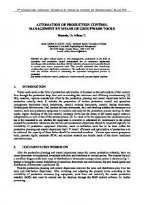
Figure 1: Layout and Workflow of a Production Automation System.
Figure 1 illustrates the interaction between some business and engineering roles to design and run a production automation system: workflows (e.g., work order scheduling, workshop coordination and machine assignment) and involved stakeholders (in our case: dispatcher, workshop integrator and operator, systems engineers, and machine vendors). During the engineering process efficient data exchange approaches are necessary to keep an overview on the process status and ensure that shared data elements are consistent at relevant milestones between individual stakeholders from different disciplines, i.e., engineers in the electrical, software, process, and mechatronic application domains. In production automation manufacturing systems a flexible systems design of the workshop layout is desirable to enable fast response to changed work orders and minimize systems downtime in case of changes or defects [27]. Production automation research systems. As production automation system for research the Manufacturing Agent Simulation Tool (MAST) [25] provides a unique combination of multi-agent-based manufacturing control features and a simulator of the manufacturing environment similar to the system illustrated in Figure 1. The system can represent the full range of roles involved in such a complex system: business orders, workshop scheduling strategies, robust workshop control, and control of individual machines in the workshop. The Simulator of Assembly Workshops (SAW) [17] is an extension of the original MAST simulator providing means
for automatic execution and evaluation of a predefined set of simulation experiments that can be used for comprehensive statistical data analysis. B. Semantic Integration of Engineering Knowledge Semantic integration bridges semantic gaps in software and systems engineering environments between project participants who use different terms for common domain concepts, i.e., concepts that exist in at least two participating domains, such as orders, components, and signals. The core question is how to translate the content of messages between systems that use different local terminologies for common concepts in their domain of discourse, so these systems can understand each other and conduct a meaningful conversation [1, 9, 19]. Engineering knowledge representation with ontologies. A key concept of semantic integration is to provide a machine-understandable representation of knowledge that facilitates the mapping between facts and the derivation of new facts from the modeled knowledge. In the production automation domain there exist several types of engineering knowledge: local engineering models of particular engineering tools (classes and instances), which use common concepts to enable data exchange, environment information, e.g., on stakeholder roles, processes, tools, and relationships between these entities, and meta-information on data elements, e.g., which stakeholder roles are interested in certain data entities. Ontologies provide effective mechanisms for storing all different types of engineering knowledge, while preserving the original syntax or terminologies and linking knowledge elements using mappings between them. An ontology is a representation vocabulary for a specific domain or subject matter. The ontology does not seek to describe all the knowledge contained in a domain, but only the knowledge essential for conceptualizing the domain [8]. The use of ontologies for knowledge representation, sharing and high-level reasoning is a major topic in the area of designing flexible and autonomous systems, such as agentbased control systems [23]. Ontologies are necessary for enabling data-driven system configuration and reconfiguration in an extensible manner. The use of domain ontologies for representing knowledge in the factory automation domain has been proposed [10]. Semantic mapping of knowledge. Semantic integration is defined as the solving of problems originating from the intent to share information across disparate and semantically heterogeneous data. These problems include the matching of data schemas, the detection of duplicate entries, the reconciliation of inconsistencies, and the modeling of complex relations in different sources [22]. In an engineering context common engineering concepts can be used as basis for mappings between proprietary tool-specific engineering knowledge and more generic domain-specific engineering knowledge to support transformation between these engineering tools. Engineering knowledge descriptions in ontologies can be the basis to provide mappings between these ontologies to enable semantic integration. Noy [21] identified three major dimensions of the application of
ontologies for supporting semantic integration: the task of finding mappings (i.e., semantic correspondences) semiautomatically, the declarative formal representation of these mappings, and reasoning using these mappings. Semantic mappings can either consist of elements of the same granularity, such as 1:1 mappings of concepts or attributes, or in addition may be expressed using different levels of granularity, such as mapping the attribute of a concept to a target concept or mapping a concept to all inherited subconcepts of a target concept. III.
RESEARCH ISSUES
The scope of our work is an ASE team consisting of experts from several engineering disciplines, who work on engineering process tasks with role-specific tools and systems that encapsulate engineering models and project data. As the engineers work together to deliver a product to the end user, they inevitably have to form common concepts on deliverables at interfaces between their work tasks. Such common concepts can be found in elements of requirements, design, and defect descriptions, which concern more than one role. Typical requirements for such engineering process tasks are low delay, i.e., in-time availability of information from other engineering tools and low effort for achieving the information exchange between the engineering tools. Each engineering role has a tailored tool set that works on data relevant to the engineer’s tasks. In order to support the data exchange between these engineering tools, an additional component is needed. Currently, in a typical process step in the engineering process an engineer exports data from his tool to a transfer document (e.g., PDF of data table) and saves this document in a common repository accessible by a set of partner engineering tools. As alternative to the traditional approach we propose the novel Engineering Knowledge Base (EKB) framework. In comparison to a simple data storage such as a common repository, a knowledge base stores information (i.e., the original data plus meta-data describing links between data elements or annotations of data elements) which can be used to automate time-consuming tasks and support human experts in doing their work. In this paper, we evaluate and discuss the benefits and limitations of the proposed EKB framework in comparison to a traditional solution using a common repository, in particular, more efficient support for data exchange between automation systems engineering tools. Key goal is to investigate to what extent the explicit and machineunderstandable knowledge stored in the EKB helps support time-consuming ASE processes, such as data exchange between tools or model checking across tools. Relevant derived research issues for investigation are: 1. What are the advantages of using the EKB framework for these processes, compared to a common repository? 2. Investigate whether the EKB framework provides an overall more efficient and effective ASE process regarding typical requirements for engineering process tasks such as low delay, low effort for achieving the information exchange between the engineering tools, and flexibility of the approach regarding the involved engineering tools and data definitions.
3. Analyze how the extra effort for involving the EKB framework is likely to pay off in a typical engineering context. For investigating the research issues we gathered requirements from a set of use cases from an industry case study. Based on these use cases we designed the architecture of the EKB framework and the empirical evaluation. IV.
ENGINEERING KNOWLEDGE BASE FRAMEWORK AND USE CASE
This section introduces the Engineering Knowledge Base (EKB) framework and describes its architecture. Additionally, we identify a set of use cases from assembly workshop engineering, describe the use cases in the context of the SAW production automation research system, and show how these use cases are supported by the EKB framework. The top part of Figure 2 illustrates the use case scenario with the EKB framework for engineering an assembly workshop for the SAW production automation system. In this example, there are two types of engineers (electrical engineer, software engineer) who come from to different engineering domains respectively. These roles use specialized engineering tools for their tasks. These tools contain local data sources, which produce and/or consume data with heterogeneous data structures. The EKB is used to facilitate the efficient data exchange between these engineering tools and data sources by providing a so-called “virtual common data model”. Based on this data exchange, more complex engineering process tasks like model checking across tools are supported. The bottom part of Figure 2 shows the internal architecture of the EKB. The general mechanism of the EKB framework uses common engineering concepts identified beforehand as basis for mappings between proprietary tool-specific engineering knowledge and more generic domain-specific engineering knowledge to support transformation between these engineering tools. In the following, the internal architecture of the EKB is described in detail: Extraction of Tool Data (1). As first step, the data elements contained in a particular tool need to be extracted in order to be available to the EKB framework. Since by now only a few engineering tools provide APIs for directly accessing the contained data, the export functionality of the tools is used. The exported data then is parsed and transformed into an internal format consisting of key-value pairs for each data attribute, which is easier to handle. Storage of Extracted Tool Data (2). The extracted and transformed key-value pairs are stored using a Java Content Repository (JCR) 1 implementation, the so-called Engineering Data Base (EDB). For data storage, a tree structure is used, and additional functionality like versioning or roll-back is provided. The EDB is indexed and can be queried using Apache Lucene2.
1 2
http://jcp.org/en/jsr/detail?id=283 http://lucene.apache.org/
Description of Tool Knowledge (3a). The tool ontologies define the engineering-tool-specific, proprietary view on the information exchanged (e.g., a list of signals) in an integration scenario. This includes the view on the format of the information, but can also describe the meaning or the use of the specific view on the existing information, since there can exist multiple views for the same information. The most important part of this description is the definition of the exchanged information, i.e., the definition of the data structures either provided or consumed by a tool. Description of Domain Knowledge (3b). The domain ontology contains the relevant shared knowledge between stakeholders in the particular application domain (in our case the Production Automation domain) and hence represents the collaborative view on the information exchanged in an integration scenario. In addition, the domain ontology is the place to model standardized domain-specific information (e.g., the description of concepts used throughout an application scenario such as the application domain independent description of business orders or machines in the context of the SAW production automation system). The proprietary information of the engineering tools, which is defined in the tool ontologies, is mapped to the more general information of the domain ontology in order to allow the interoperability with other engineering tools. In contrast to a common data schema, the knowledge stored in the domain ontology is defined on a more general domain level compared to the knowledge stored in the tool ontologies. This particular domain-specific knowledge described in the domain ontology can easily be updated or transferred to other EKB-based integration scenarios residing in the same domain. This approach allows a broad spectrum of new applications in a particular domain to benefit from the described domain knowledge. In order to support the creation of tool and domain ontologies, we assume that the models are available using well-established modeling standards, e.g., EER diagrams. The models can then easily be transformed into valid OWL ontologies, e.g., by using UML2OWL3. If required, the fine-tuning of the ontologies can be performed using an ontology editor, e.g., Protégé4. Mapping of Tool Knowledge to Domain Knowledge (4). Each data structure segment described in the tool ontology is mapped to either exactly one particular corresponding domain concept or domain concept attribute described in the domain ontology, or to e.g., all inherited sub-concepts of a target concept. In addition, the granularity of the mapped elements does not need to be the same, so that e.g., a concept can be mapped to the attribute of another concept, or vice versa. This defines the semantic context of the information contained in the segment and allows the detection of semantically similar information consumed and produced by other engineering tools. In addition, the format of the information is described, enabling an automated transformation from source to target format. The mapping process can be supported by applying Ontology Alignment methods to provide hints regarding possible mappings. 3 4
http://diplom.ooyoo.de http://protege.stanford.edu/
Figure 2: EKB Use case scenario. Usage of the EKB (5). The mapping of concepts described in the tool ontologies to common concepts described in the domain ontology allows the creation of transformation instructions. These transformation instructions are the foundation to transform data structures between two engineering tools, because the engineering tools may label or format their data structures in different ways. Due to the mappings between tool ontologies and domain ontology data structures that are semantically equal can be identified, because they are either aligned to the same domain concept or belong to the same tree segment in the concept tree described in the domain ontology. The transformation instructions can be defined in XML syntax and consist of at least one input and output data structure segment. The segments contain a unique ID and instructions, how the input segment is transformed to an output segment. There is a set of basic transformations that can be combined to more complex transformations, like changing the name of a segment, converting the format using converters, merging or splitting a set of input segments or querying external services for transformation [20]. Based on these transformations, more complex applications can be implemented which use the integrated data of the virtual common data model to perform advanced tasks like tracing of artifacts, consistency checking across tool boundaries, change impact analyses or notification of stakeholders in case of changes. Now that we have described the general mechanism and the internal architecture of the EKB framework, the next step is the setup and configuration of the EKB framework. As described in [5], we suggest to use an enterprise service busbased approach to integrate engineering tools by describing
the data structures they produce and consume as services. The EKB framework acts as a component in the proposed technical integration solution, which performs its transformation service on the message transmitted using the enterprise service bus. After the EKB is set up and configured properly, we show how the EKB framework supports typical engineering tasks, illustrated in the context of the SAW production automation research system. In this paper we focus on two fundamental use cases for model checking across tool boundaries in the production automation engineering context. UC-1: Model consistency checking across tool boundaries. Model checking, i.e., the validation of model data elements regarding their integrity and consistency, typically is performed at project milestones before the model elements can be used in the next stage of engineering. For a safety-critical domain such as the production automation domain, model checking is required for obtaining relevant system certifications. Currently, model checking is limited to single engineering tools or domains. In addition to syntactical checks, plausibility checks of elements regarding their usage in other engineering domains are needed. UC-2: Impact analysis of model value changes. In difference to single system models, where changes of model values have direct impacts on other model elements, model value changes in cross-domain modeling require additional transformation and checks before the actual impact of a value change can be estimated or measured. In the SAW research system model checks are necessary after concurrent engineering model changes to ensure that models do not violate design constraints. Design-time model checks include checking the workshop layout validity and the availability of
all machine functions needed for valid production orders. Run-time model checks include checking sufficient machine capacity for producing orders planned for a shift and checking the impact of relevant machine/conveyor failures on the overall production output. V.
EVALUATION OF THE EKB SUPPORT FOR ENGINEERING TASKS
In this section, we evaluate the two use cases described in section 4 both for a traditional approach using a common repository and for the novel EKB framework. A. UC-1: Model checking across tool boundaries. Model checking refers in the evaluation study context to the inspection of model data elements regarding their consistency and integrity. As a first step towards comprehensive model checking, checks of local data structures belonging to a specific engineering tool can be performed. For these checks, no access to data structures of other engineering tools is needed. However, since the data structures of the single models are viewed independent of the data structures of other engineering tools, more advanced checks regarding a combination of data structure of multiple engineering models. For this use case, we focus on two types of models checks, namely a) consistency and integrity checks of model changes; and b) the derivation of runtime functionality for automated testing and monitoring. An example for consistency and integrity checks of model changes is a hardware pump which supports a certain number of input/output signals (I/Os), and which is controlled by a pump control software using either analog or digital signal processors. Analog signal processors can handle 8 I/Os, digital 64 I/Os. If the signal processor type is changed in the pump control software model, it needs to be validated whether the new signal processor type can handle all available I/Os of the hardware pump. Respectively, if the I/Os are changed (e.g., new I/Os added) it has to be checked whether they all can be controlled using the chosen signal processor type of the pump control software. Another example for the derivation of runtime functionality for automated testing and monitoring is again a hardware pump which can handle approximately 1000 liters per hour. A time-based analysis of the events originating from the reservoir located behind the hardware pump could show impossible conditions or sensor states, e.g., if the reservoir capacity of 10000 liters is reached within 5 hours starting from an empty condition. Common Repository Approach. Using a common repository enables to perform advanced checks regarding the data structures of more than one engineering tool, such as checking the consistency of single data structure elements across tool boundaries or analyzing the possible impact of changes to data structures belonging to a specific engineering tool on the data structures of other engineering tools. The major drawback of this approach of performing model checks is the need for manual involvement of human experts. The experts need to explicitly define the checks and select the data they want to include in these checks. This definition needs to be updated after every change to the involved data
elements. Additionally, the nature of the common repository allows only for syntactical checks (e.g., the availability of all obligatory data fields or the validity of data types regarding a certain data schema) of the data, but not for other checks such as regarding the semantic correctness or plausibility of data structures. Other checks, such as checks regarding logical connections of data elements, are not supported out of the box using a common repository, since the data elements in the repository are stored unaltered and without metainformation. However external analysis tools can use the data elements stored in the common repository for performing such model checks. Engineering Knowledge Base (EKB) Approach. The EKB framework enables automated checks regarding both syntactical issues as well as plausibility checks regarding semantic correctness of data structures. The EKB framework exploits the querying capabilities of ontologies to allow even more advanced checks, such as checks regarding completeness of available information. Human experts define checks regarding specific domain or tool-specific concepts, which are then on-the-fly transformed into checks regarding tool-specific data structures accordingly. The results are then collected and again transformed into the domain concept level, allowing experts both to define checks as well as to view the results of the defined checks in their well-known syntax, terminologies and notations. B. UC-2: Analyses using information from multiple stakeholder domains. The problem described here corresponds to the sales manager’s task of identifying the maximal amount of products that can be produced during a shift. To do this task, the sales manager needs to collect information from other stakeholders and make calculations based on the information collected before getting to the final result. workshop:shift1 workshop:lasts workshop:14400 workshop:shift1 workshop:order workshop:prod6 business:prod6 business:finishingTime business:50 SELECT(?x) WHERE {sales:shift1 sales:lasts ?x} SELECT(?x) WHERE {global:shift1 global:lasts ?x} SELECT(?x) WHERE {manager:shift1 manager:lasts ?x} Result: x = manager:14400 manager:14400 owl:equalTo global:14400 SELECT(?y) WHERE {global:prod6 global:finishingTime ?y} SELECT(?y) WHERE {business:prod6 business:finishingTime ?y} Result: y = business:50 business:50 owl:equalTo global:50 SELECT(?z) WHERE {?x owl:equalTo global:shiftTime ?y owl:equalTo global:finishingTime global:prod6 global:has ?z: x/y) Result: z = global:288 global:288 owl:equalTo sales:288 Listing 1: EKB Framework Example - Identify the maximal amount of products which can be produced in a shift.
Common Repository Approach. All information of the process production is placed in the common repository. The sales manager retrieves the needed information out of the common repository, while the other stakeholders put the information in the common repository. The drawbacks of this approach are updates submitted by different stakeholders that are hard to handle concurrently, and different formats and syntax originating from different stakeholders. The sales manager has to deal with other data not necessarily needed for his tasks and manual and therefore error-prone steps are required to get the needed data from other stakeholders. EKB Approach. By using the EKB framework, the automated analyses are supported using the following these steps (refer also to Listing 1 for a detailed description of these steps using simplified OWL 5 syntax): The sales manager queries the global view to find out the current shift time. The shift time is identified in the global view and the mapping of the shift time to the workshop manager’s local view is exploited, and subsequently the shift time is queries in the workshop manager’s local view and represented in the global view. As next step, information about the finishing time of the product type of product prod6 is queried in the global view, resulting again in an exploiting of the mapping to the business manager’s local view, a query of this local view and a representation of the product type and finishing time of the product prod6 in the global view. Finally, in the global view the maximum amount of products that can be produced in the current shift is calculated using the previously queried information and the result is presented to the sales manager. VI.
DISCUSSION
This section discusses the described EKB framework as well as the initial results of the evaluation with regard to the research issues regarding more efficient support for data exchange for automation systems engineering. 1. What are the advantages of using the EKB framework for these processes, compared to using a common repository? The explicit and machineunderstandable knowledge in the EKB framework helps to automate time-consuming automation systems engineering process steps like the exchange of data structures between heterogeneous engineering tools or consistency and completeness checks of data structures. Further, the EKB allows automating later integration processing steps, like automatically generating transformation instructions for data structure exchange between the integrated engineering tools. The major difference between the two evaluated approaches is the lack of the need for a common data schema when using the EKB framework, which can be seen as the main advantage of the EKB framework compared to a common repository. However, additional expert skills are necessary when using a fairly new technology in a quite traditional application context. 2. Investigate whether the EKB framework provides an overall more efficient and effective ASE process regarding typical requirements for engineering process 5
http://www.w3.org/TR/owl-semantics/
tasks such as low delay and low effort for achieving the information exchange between the engineering tools. The advantage of centrally storing the domain knowledge together with the mappings of individual tool knowledge lies in the possibility of an automated QA and automation of further engineering process steps. As described in [3], using ontologies for storing the knowledge in the EKB framework, enables more efficient and effective QA for componentbased systems such as production automation systems. The major differences between the two evaluated approaches are the amount of needed human involvement to define and perform model checks, and the types of model checks which are supported by the approaches. 3. Analyze how the extra effort for involving the EKB framework is likely to pay off in a typical engineering context. The evaluation showed that the effort needed for certain automation systems engineering process steps with the EKB framework is slightly higher in case of performing it from the scratch, but comparatively a lot smaller when adaptations due to changing business needs have to be performed since new converters only need to be generated semi-automatically for each new or changed engineering tool in comparison to the need of creating or adapting a vast number of converters for each affected combination of the new or changed engineering tool manually. The evaluation use cases supported the feasibility of the EKB approach and promising initial results. However, practical issues such as effort and defect rates for setting up an EKB with larger-scale data models and for semantic mapping with engineering experts need to be explored in settings with industrial experts. VII. CONCLUSION AND FURTHER WORK Industrial production automation systems depend on distributed software to control the system behavior. In automation systems engineering (ASE) software engineering depends on specification data and plans from a wide range of business, process, and engineering expert domains in the overall engineering process, e.g., physical plant design, mechanical, and electrical engineering, and production process planning. In heterogeneous ASE environments capabilities for the effective and efficient integration of engineering systems and semantic integration of engineering knowledge are key enablers for flexible engineering process automation and advanced quality management. However, a major challenge in current industrial research approaches is insufficient model integration between the expert disciplines. In this paper, we introduced the novel Engineering Knowledge Base (EKB) framework for semantic mapping in ASE with a focus on providing links between data structures of engineering tools and systems to support the exchange of information between these tools and thus making ASE more efficient and flexible. Based on two real-world use cases of the SAW system, a research system for assembly workshop engineering in the production automation domain, we compared the proposed EKB framework with a traditional approach using a common repository. The major difference between the two evaluated approaches is the lack of the need for a common data schema
when using the EKB framework, which can be seen as the main advantage of the EKB framework compared to a common repository as the common data schema is a source of extra maintenance effort and tool evolution risk. Additionally, the number of needed converters is O(n2) when using a common repository, compared to O(n) converters needed when using the EKB framework. Further, using the EKB framework allows a more generic definition and execution of model checks on an application domain level, and additionally enables more advanced checks regarding the plausibility and semantic correctness of data structures by exploiting the querying capabilities of ontologies. Future Work. After evaluating the feasibility of the EKB approach next steps are studies that extend the scale of the data models involved and address the following research issues: efficient import of data models into EKB ontologies, robust semantic mapping, and performance of the EKB ontologies for larger data sets. Practical issues such as effort and defect rates for setting up an EKB with larger-scale data models and for semantic mapping with engineering experts need to be explored in setting with industrial experts. Once the EKB framework is set up properly, additional use cases can be supported in order to make ASE more efficient. Planned use cases to evaluate are the tracing of requirements between data structures across tools as well as the support for change management across tools. ACKNOWLEDGMENT The authors would like to acknowledge the works of the Rockwell Automation Research Center, Czech Republic, in the field of the Manufacturing Agent Simulation Tool (MAST), as well as Liang Min and Uwe Szabo for their work regarding design and implementation of the SAW prototype. This work has been supported by the Christian Doppler Forschungsgesellschaft and the BMWFJ, Austria, and partially funded by the Vienna University of Technology, in the Complex Systems Design and Engineering Lab. REFERENCES [1] L. Aldred, W.v.d. Aalst, M. Dumas, and A.t. Hofstede, “Understanding the Challenges in Getting Together: The Semantics of Decoupling in Middleware,” BPM Center Report BPM-06-19, 2006. [2] P. Baker, R.D. Zhen, J. Gabrowksi, and H. Oystein, Model-Driven Testing: Using the UML Testing Profile, Springer, 2008. [3] S. Biffl, R. Mordinyi, T. Moser, and D. Wahyudin, “Ontologysupported quality assurance for component-based systems configuration,” Proc 6th Intl Workshop on Software quality, ACM, 2008, pp. 59 - 64. [4] S. Biffl, T. Moser, W. Sunindyo, “Bridging Semantic Gaps Between Stakeholders in the Production Automation Domain with Ontology Areas,” 21st Intl Conf on Softw Eng and Knowl Eng, 2009, pp. 233-239. [5] S. Biffl, A. Schatten, and A. Zoitl, “Integration of Heterogeneous Engineering Environments for the Automation Systems Lifecycle,” IEEE Industrial Informatics Conf., 2009, pp. 576-581. [6] N. Fenton, and M. Neil, “A Critique of Software Defect Prediction Models,” IEEE Trans. on Software Engineering, vol. 25, 1999, pp. 15. [7] GAMP 5, “Good Automated Manufacturing Practice,” International Society for Pharmaceutical Engineering (ISPE), 2008.
[8] T. Gruber, “Towards principles for the design of ontologies used for knowledge sharing,” Int. J. Human-Comp. Studies, vol. 43, no. 5/6, 1995. [9] G. Hohpe, “Conversation Patterns,” Dagstuhl Wshp Report, 2006. [10] J.L.M. Lastra, I.M. Delamer, and F. Ubis, Domain Ontologies for Reasoning Machines in Factory Automation, ISA o3neida, 2009. [11] P. Li, J. Herbsleb, and M. Shaw, “Forecasting Field Defect Rates Using a Combined Time-Based and Metrics-Based Approach: Case Study of OpenBSD,” 16th Intl Symp on Software Reliability Eng, IEEE, 2005. [12] S. Liao, “Technology management methodologies and applications: A literature review 1995-2003,” Technovation, 25(4), 2005, pp. 381-393. [13] P.J. Lovett, A. Ingram, and C.N. Bancroft, “Knowledge-based engineering for SMEs - a methodology,” Journal of Materials Processing Technology, vol. 107, no. 1-3, 2000, pp. 384-389. [14] A. Lüder, “Formaler Steuerungsentwurf mit modularen diskreten Verhaltensmodellen,” PhD, Martin-Luther-Universität, Halle, 2000. [15] A. Lüder, J. Peschke, and D. Reinelt, “Possibilities and Limitations of the Application of Agent Systems in Control,” International Conference On Concurrent Enterprising (ICE), 2006. [16] J. McGuire, D. Kuokka, J. Weber, Tenenbaum, J. M., T.R. Gruber, and G.R. Olsen, “SHADE:Technology for Knowledge-based Collaborative Engineering,” Concurrent Engineering, 1, 1993, pp. 137-146. [17] M. Merdan, T. Moser, D. Wahyudin, and S. Biffl, “Performance evaluation of workflow scheduling strategies considering transportation times and conveyor failures,” IEEE Intl Conf on Industrial Engineering and Engineering Management, 2008, pp. 389-394. [18] A. Mockus, D. Weiss, and P. Zhang, “Understanding and Predicting Effort in Software Projects,” Intl Conf on Software Engineering, 2003. [19] T. Moser, R. Mordinyi, W. Sunindyo & S. Biffl, “Semantic Service Matchmaking in the ATM Domain Considering Network Capability Constraints,” 21st Int. Conf on Sw Eng and Knowl Eng, 2009, pp. 222-227. [20] T. Moser, K. Schimper, R. Mordinyi, and A. Anjomshoaa, “SAMOA - A Semi-automated Ontology Alignment Method for Systems Integration in Safety-critical Environments,” 2nd Intl Wsh on Ontology Alignment and Visualization, IEEE, 2009, pp. 724-729. [21] N.F. Noy, “Semantic integration: a survey of ontology-based approaches,” SIGMOD Rec., vol. 33, no. 4, 2004, pp. 65-70. [22] N.F. Noy, A.H. Doan, and A.Y. Halevy, “Semantic Integration,” AI Magazine, vol. 26, no. 1, 2005, pp. 7-10. [23] M. Obitko & V. Marik, “Ontologies for MAS in Manufacturing Domain,” 13th Intl Wsh on Datbases and Expert Systems Applications, IEEE, 2002. [24] W. Schäfer, and H. Wehrheim, “The Challenges of Building Advanced Mechatronic Systems,”Future of Software Engineering, IEEE, 2007, pp. 72-84. [25] P. Vrba, “MAST: Manufacturing Agent Simulation Tool,” Emerging Technologies and Factory Automation, IEEE, 2003, pp. 282-287. [26] D. Wahyudin, A. Schatten, D. Winkler, A. Tjoa, and S. Biffl, “Defect Prediction using Combined Product and Project Metrics: A Case Study from the Open Source "Apache" MyFaces Project Family,” Proc 34th Conf on Software Eng and Advanced Applications., IEEE, 2008, pp. 207 - 215. [27] D. Winkler, S. Biffl, and T. Östreicher, “Test-Driven Automation – Adopting Test-First Development to Improve Automation Systems Engineering Processes,” 16th EuroSPI Conference, 2009.