Integration of Call Signaling and Resource Management for IP Telephony Pawan Goyal, Albert Greenberg, Charles R. Kalmanek, William T. Marshall, Partho Mishra, Doug Nortz, and K. K. Ramakrishnan AT&T Laboratories Abstract IP telephony presents a tremendous opportunity to service providers to offer both traditional services as well as a range of creative new services. However, there are substantial challenges to be faced in supporting a resource management framework that is adequate for telephony, and in providing a signaling architecture that enables these services while preserving user privacy and preventing theft of service. This article describes the Distributed Open Signaling Architecture, a framework for call signaling and resource management that meets these needs. A key contribution of our work is a recognition of the need for coordination between call signaling, which controls access to telephony-specific services, and resource management, which controls access to network-layer resources. We evaluate one approach to resource management in the backbone, consistent with our architecture, using signaling for aggregates of flows. Using traces from calls on the AT&T long distance network, we show that the multiplexing gains achieved by such aggregation can achieve most of the benefits of per-flow signaling, while avoiding its overheads. We also evaluate scheduling algorithms in order to understand their effect on the end-to-end delay experienced by voice packets.
T
he advent of IP telephony gives service providers a tremendous opportunity to offer both traditional services as well as a range of creative new services that integrate voice communications with data applications and exploit the power of intelligent end terminals. While services will continue to be provided through conventional telephones, the potential interaction with the network will increase through enhanced user interfaces. At the same time, IP telephony poses substantial challenges. The signaling architecture must support both traditional services and new services enabled by intelligent end-points, while preserving user privacy and preventing service theft. User expectations of quality impose stringent requirements on both network and signaling performance. Meeting the network performance requirements calls for a resource management framework that ensures adequate capacity for voice everywhere along the end-to-end path. IP networks are evolving to provide multiple levels of service. The revenue models may be different for each service, and a provider may wish to derive additional revenue from an enhanced service such as telephony. Because users will have access to multiple communication capabilities, the provider needs to find incentives to use and pay for these enhanced services. Otherwise, users are likely to bypass them by using protocols and functionality implemented in the end systems.
24
0890-8044/99/$10.00 © 1999 IEEE
A provider can offer at least three fundamental incentives to encourage the use of an enhanced service as opposed to a lower priced, best-effort data service: • Dependable quality of service (QoS) assurances. For telephony, these assurances are primarily in the form of low delay and low loss, to ensure that speech quality meets user expectations. • Services that truly belong in the network, especially those that rely on a trusted intermediary. • Functionality that is much more cost-effective, and easy to provide and use in the network. We believe that a difference in network-layer QoS is essential to robust IP telephony service. As a result, the network must support resource reservations and admission control, allowing the resources available to the higher quality service to be managed. Even overload conditions must not lead to call defects, such as the called party answering and finding no resources to support communication between the two endpoints. Since the network is providing enhanced QoS, the signaling architecture must ensure that the use of enhanced service is authorized and accounted for. This article describes the Distributed Open Signaling Architecture (DOSA), which incorporates call signaling and resource management functions to meet the needs of telephony. A key contribution of our work is a recognition of
IEEE Network • May/June 1999
the need for coordination between call signaling, which controls access to telephony-specific services, and resource management , which controls access to network-layer resources. This coordination provides critical functions to ensure that: • Users are authenticated and authorized before receiving access to the enhanced QoS associated with the telephony service. • Network resources are available end to end before ringing the destination phone. • Resource usage is properly accounted for, consistent with the semantics of telephony in which charging occurs only after the called party picks up. The explicit coordination between call signaling and resource management is a key distinction between DOSA and other proposed signaling architectures for IP telephony, including the H.323 series of Recommendations [1], the Media Gateway Control Protocol (MGCP) [2], and the Session Initiation Protocol (SIP) [3]. In this article, we present the application requirements that drive the DOSA design, followed by a description of the architecture itself. Then we outline resource management mechanisms, consistent with DOSA, for meeting the QoS requirements of telephony service. We also present simulation results quantifying the performance of these mechanisms.
Application Requirements The Distributed Open Signaling Architecture was designed to meet “first-line” telephone service requirements, comparable to circuit-switched telephone service. Because of the large embedded base, the service must support existing customer premises equipment, including conventional telephones and legacy voiceband data equipment such as fax machines and modems. It must also support the broad range of service features currently available. These include basic telephony features such as emergency 911 service, operator services, and law enforcement wiretapping, as well as popular optional features such as call forwarding, caller ID, call waiting, and three-way calling. In addition, first-line telephone service has stringent requirements for speech quality, signaling performance, reliability, and scalability. Users have come to expect highly reliable and available telephone service. To be acceptable by the mass market as a circuit-switched replacement, the service must be available 99.9+ percent of the time. While reliability must be built into the network elements, it must also be designed into the network and signaling architectures. First-line telephony performance requirements include: • Low delay. End-to-end packet delay must be small enough not to interfere with normal voice conversations. • Low packet loss. Packet loss must not perceptibly impact either voice quality or the performance of fax and voiceband modems. • Short post-dial delay. The delay between the user dialing the last digit and receiving positive confirmation from the network must not perceptibly differ from post-dial delay in the circuitswitched network. • Short post-pickup delay. The delay between a user picking up a ringing phone and the voice path being cut through must be short enough that the initial “hello” is not clipped. These performance requirements affect the design of both the signaling and network architectures. In this article we concentrate primarily on resource management mechanisms necessary to ensure that voice receives adequate performance from the network layer.
IEEE Network • May/June 1999
Delay Metrics Recommendation G.114 of the International Telecommunication Union — Telecommunication Standardization Sector (ITU-T) provides guidelines on the tolerable delay for a normal telephone conversation, based on extensive testing carried out over three decades. The maximum one-way delay acceptable for most user applications is given as 150 ms, but the Recommendation notes that some highly interactive voice and data applications may experience degradation even at this point. Therefore, it is critical to manage delay carefully. The 150-ms one-way delay limit must be allocated among several different sources, producing a delay budget. The single biggest component of the delay budget is backbone transport. The longest path in the continental United States is between Seattle, Washington, and Orlando, Florida. However, if we consider the possibility of facility failure along this path, the restoration path may be routed from Orlando to Los Angeles, to Chicago, to San Francisco, to Seattle (when the Los Angeles-to-San Francisco facilities are out of service). This worstcase one-way delay has been measured at 95 ms. This leaves a remaining delay budget of only 55 ms (one-way) for all other sources.1 Delays encountered in the transmission path can be characterized as fixed or variable. Fixed delays, such as propagation time, will be the same for every data packet. Variable delays or “jitter,” such as queuing and media access, may vary from one packet to the next. Therefore, a playout buffer is required at the receiving side to “dejitter” the packet stream. It is important to note that simply adding fixed and variable delay does not calculate total delay. The jitter must actually be counted twice in the delay budget, once as potential delay in the transport network and once at the playout buffer in the receiver. When the first packet of a conversation reaches the playout buffer, it must be delayed by an amount equal to the allocated jitter in the network before starting to play out voice. If that packet had accumulated zero jitter in transport, the buffer is now set correctly to handle all further packets whether they are jittered or not. If that first packet was delayed by the maximum jitter in transport, the playing out of voice is actually delayed by twice the jitter value. A representative delay budget can quantify the maximum queuing delay that can be introduced in the backbone. Consider the 150-ms one-way delay bound. Backbone propagation reduces the available delay to 55 ms. Allocate 10 ms to the speech coder, 10 ms to speech enhancement and silence suppression, and 5 ms to processing, propagation, and interleaving in the local access network. The remaining 30 ms is available for variable delay factors, which allows a 15-ms playout buffer at the receiver and a maximum 15-ms jitter tolerated in transit. Of this 15-ms jitter budget, we allocate 5 ms to the access network, leaving 10 ms for queuing delay in the backbone network. We return to the subject of backbone queuing delay later.
Packet Loss Metrics Typically, the requirements for packet loss for encoded speech are 1 percent or less. While loss-concealment algorithms can be used to reproduce intelligible speech even with higher loss rates, the resulting performance is inadequate as a circuitswitched replacement. Loss requirements for acceptable voiceband modem performance are even more stringent. 1 We have not considered international calls here, for which delay management is an even more important consideration.
25
Gate controller
Gate controller
flows, they generate the accounting events that allow a user to be charged for service. Edge routers can also implement network address translation to support IP address privacy for both the CPE CPE ER ER called and calling parties. Gate controllers provide the policy Access network function that determines whether a gate PSTN should be opened. DOSA signaling sets GW up a gate in advance of a reservation request. This allows the gate controller ER: Edge router Local PSTN to be “stateless” in that it does not need CPE: Customer premises equipment LD to know the state of calls already in progress. Because the gate is set up in ■ Figure 1. Key components of the Distributed Open Signaling Architecture. advance, the gate controller provides an upper bound or envelope of acceptable traffic parameters to the ER, in addiDistributed Open Signaling Architecture tion to the source and destination addresses, port pairs, and protocol identifier. When the CPE makes a resource reservation request by signaling to the network, the ER admits the This section describes the key components of the DOSA reservation if it is within the envelope specified in the gate architecture and uses a simple call flow to illustrate how these setup. interact to support telephony service. While the DOSA signalGate controllers implement a set of service-specific control ing protocol supports service features implemented by the functions required to support the telephony service: endpoints, the details of these feature flows are beyond the • Authentication and authorization. Gate controllers authentiscope of this article. cate signaling messages and authorize requests for service Components on a call-by-call basis. • Number translation and call routing. Gate controllers transFigure 1 illustrates the key components in the architecture. late dialed E.164 numbers to a terminating IP address Telephony clients, such as PCs or multimedia terminal adapbased on call routing logic to support a wide range of call tors, interface between a conventional telephone and a local features. area or access network. Telephony clients participate in end-to• Service-specific admission control. Gate controllers can end capability negotiation, call signaling, and resource reservaimplement a broad range of admission-control policies for tion protocols. Edge routers (ERs) connect the access network the telephony service. For example, gate controllers may to a managed IP backbone. In our architecture, ERs implement provide precedence for particular calls, such as 911 calls. a function called a gate, which is a policy enforcement function Admission control can also be used to implement overload that controls access to higher-quality service from the network control mechanisms, for example, to restrict the number of layer. Gate controllers control the gates and provide servicecalls to a particular location or to restrict the frequency of specific functions, such as number translation, authorization, call setup to avoid signaling overload. and feature support. Media servers are network-based compo• Signaling and service feature support. Many service features are nents that play terminating announcements, perform audio implemented in the CPE, but the gate controller also plays a bridging, and so on. Finally, public switched telephone netsupport role. DOSA signaling provides a set of service primiwork (PSTN) gateways interface to the PSTN. tives to endpoints that are mediated by the gate controller. For robust telephony service, the service provider must manThe gate controller is involved in implementing service feaage access to network-layer resources. Admission control is tures that depend on the privacy of calling information, such provided by trusted ERs at the boundary to the backbone netas caller ID blocking). It also plays a role in supporting serwork. The ERs support both resource-based and policy-based vice features that require users to receive a consistent view admission-control functions, allowing the IP network to ensure of feature operation even when CPE is down. the bounded loss and delay required by telephony service. The gate controller is designed as a stateless transaction ER-implemented gates support packet classification and server so that failure of a gate controller does not affect stable policing to ensure that only IP flows authorized by the gate calls. Since the interactions with the gate controllers are statecontroller are granted access to enhanced QoS in the access less, there is no need for consecutive calls to be processed by and backbone networks. Gates allow a flow of packets from a the same gate controller. This design places the management specific IP source address and port to a specific IP destination of a call’s state where it belongs: at the CPE. Only the CPE address and port to receive enhanced QoS. Gates are opened and the network elements along the data path are required in for individual calls. Opening a gate involves an admission-conproviding service for ongoing calls. We believe that this design trol check, which is performed when a reservation request is makes the gate controller efficient and highly scalable, and received from the customer premises equipment (CPE) for an the network architecture more reliable. individual call. Opening a gate may involve reservation of resources in the network for the call, where and when necesSimple Call Flow sary. Once a gate is opened, the ER participates in providing enhanced QoS service, by either marking the packets or queuFigure 2 shows the message exchanges associated with basic ing them as a particular QoS-assured flow. call setup, illustrating the relationship between the call signalERs require authorization from a gate controller on a call-bying, resource management, and policy functions. call basis before opening a gate. Thus, the ER can ensure that When a user goes off-hook and dials a telephone number, enhanced QoS is only provided for authorized end-to-end flows the originating CPE (CPEO ) collects the dialed digits and that have usage accounting mechanisms in place. Since ERs sends a SETUP message to the originating gate controller know about the resource usage associated with individual IP (GC O). Note that providing service to untrusted endpoints
26
Media server
IEEE Network • May/June 1999
CPEO
ERO
CGCO
GCT
ERT
CPET
SETUP requires call-by-call authorization as well as coordination with a policy GATEADMIT enforcement function that controls GATEADMITACK access to the higher quality service. As SETUP a result, GC O verifies that CPE O is a GATESETUP valid subscriber of the telephony service (using authentication information in the GATESETUPACK SETUP SETUP message). GC O may perform service-specific admission control. Since SETUPACK only ERO knows the resources currently CK PA TU SE reserved by CPEO, GCO queries it using GATESETUP a GATEADMIT request to ensure that GATESETUPACK the aggregate resources being used by CPE O do not exceed a provisioned SETUPACK limit. GC O does number translation Intermediate routers RESERVE RESERVE and call routing, augments the SETUP message with accounting information Backbone resource reservation RESERVEACK associated with the caller, and forRESERVEACK wards it to the terminating gate conRING troller (GCT). RINGBACK The GATESETUP message from GCT provides policy information to the CONNECT terminating ER (ERT) indicating that COMMIT COMMT it has permission to open a gate for the IP flow associated with this phone call. Gate coordination COMMITACK COMMITACK This policy information is kept by ERT for use when it receives a resource management request from CPET. GCT RTP flow then forwards the SETUP message to CPE T to notify it about the incoming call. CPE T sends a SETUPACK to ■ Figure 2. DOSA call flow. GCT, which forwards it to GCO. GCO informs the originating ER (ERO) that message also starts accounting for resource usage. To prevent it has permission to open a gate for the IP flow associated some service theft scenarios, the ERs coordinate the opening with this phone call, and then GCO forwards SETUPACK to of gates by exchanging gate coordination messages to ensure CPE O. At this point, the role of the gate controllers in this that both gates are opened at roughly the same time. setup is done, and the CPE and ERs proceed to the resource management phase. DOSA partitions resource management into separate Backbone Resource Management reserve and commit phases. At the end of the first phase, resources are reserved but not yet available to the CPE. At DOSA assumes that admission control and scheduling will be the end of the second phase (after the called party is rung and used in the backbone network to meet the QoS requirements answers), resources are committed and made available to the for voice flows. Admission control is needed to ensure adeCPE and recording is started so that the user can be billed for quate capacity on the end-to-end path of each admitted voice usage. The two-phase protocol is essential to the service call. Packet scheduling is required to ensure bounded end-torequirements associated with telephony. It ensures that end queuing delay for voice packets when the network capaciresources are available before ringing the far-end telephone, ty is shared with other classes of traffic having different traffic while ensuring that usage recording does not start until the characteristics and QoS requirements. To support large-scale far-end user picks up the phone. Backbone resources are service, these techniques must manage resources on an aggrereserved and allocated in the first phase to limit the impact on gate basis. For example, it may not be feasible to implement post-pickup delay. per-flow queuing and scheduling for hundreds of thousands of First, CPEO and CPET issue RESERVE messages to ER O active flows. In this section we describe admission-control and scheduling mechanisms, in concert with DOSA signaling, that and ERT, respectively. ERO and ERT perform admission condo not require per-flow state in the core of the network. We trol and, if successful, send a RESERVE_ACK to the respecalso present simulation results that examine the performance tive CPE. As soon as CPE O knows that resources are of these mechanisms as measured by their ability to meet the available, it sends a RING message to CPET instructing it to delay requirements of voice flows, and the efficiency with start ringing the phone. CPET sends a RINGBACK message which they utilize backbone network capacity. to CPEO indicating both that resources are available and that The proposed admission-control framework requires perthe RING message was received. flow signaling in the access network. The access network When the called party picks up the phone, CPE T sends a includes a small subset of routers starting from the ER, where CONNECT message to CPE O and a COMMIT message to the DOSA gates reside, up to an aggregation router (AR) ER T . CPE O sends a COMMIT message to ER O when it that interfaces to a high-capacity backbone network. Aggregareceives the CONNECT message. On receiving a COMMIT tion routers deal with per-flow requests and determine message, the ERs open their respective gates, making whether they can be satisfied. The resource management in resources available for the call. In constrained-bandwidth the backbone is for aggregate capacity required between these access networks, this may involve an interaction with the aggregation routers. layer-2 or layer-3 scheduling mechanisms. The COMMIT
IEEE Network • May/June 1999
27
Verify adequate bandwidth available on R2 → ARI link
Verify adequate bandwidth available on ARI → ARE pipe and ARE → R7 link ARI → ARE pipe
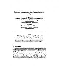
track of the available capacity (and per-flow state) for all the pipes that terminate on it. AR E also modifies the format of the RESERVE message to no longer hide this message Reserve Reserve Reserve Reserve from the intermediate routers. The Reserve RESERVE is then forwarded hop by hop toward the destination, and is ■ Figure 3. Resource reservation and admission control with pipes. processed by the routers in the path, including ERT. There are alternative models that establish an explicit association between the ingress and egress Verify adequate Verify adequate ARs. For example, the information needed about ARE can be bandwidth available on bandwidth available on integrated with the routing system [5, 6]. In this case, AR I has R2 → R5 link R2 → ARE link sufficient information about the pipe to perform the admission-control test when it receives a RESERVE message. In either case, if the admission-control check fails, the call is ARI R4 R5 ARE blocked, and the appropriate DOSA RESERVE_ACK message is generated. Aggregate QoS signaling may be used between the ingress and egress ARs to dynamically modify a pipe’s capacity. This Set_Pipe_BW Set_Pipe_BW Set_Pipe_BW aggregate QoS signaling is processed hop by hop through the (ARI → R4) (R5 → ARE) (R4 → R5) backbone, as shown in Fig. 4, and the backbone routers perform admission control and resource allocation for the aggre■ Figure 4. Pipe bandwidth management. gate capacity requested. The reservation messages for setting the pipe bandwidth in the backbone have to flow on the same path as the data. To avoid the need for per-flow admission-control checks in The capacity needed on a pipe between ARs may be deterthe backbone, we introduce the abstraction of a pipe. A pipe mined over multiple timescales. For example, the size of a is a logical link of a given bandwidth between noncontiguous pipe might be provisioned based on traffic forecasts. However, aggregation routers. Admission-control decisions for a voice resizing a pipe’s capacity dynamically allows better adaptation flow are made at the ARs on either end of a pipe, without to the traffic fluctuations resulting from day-of-week or timeinvolving any of the backbone routers. Per-flow hop-by-hop of-day effects. This can potentially reduce the aggregate signaling in the access network and per-pipe hop-by-hop sigcapacity required in the backbone if all pipes do not see peak naling in the backbone network are used only for admission traffic at exactly the same time. Resizing the pipe even more control, and do not instantiate any packet classifiers or frequently — on the order of minutes or even seconds — scheduling state at intermediate routers. Thus, it may be possaves additional capacity through multiplexing gains across sible to use pipes in combination with scheduling policies like pipes on the backbone links. In a later section we present those proposed for differentiated services (diff-serv)[4]. results illustrating that there are major capacity savings to be Figure 3 illustrates the operation of the proposed admissionrealized by resizing pipes frequently. control mechanism in conjunction with DOSA signaling. An originating ER forwards the DOSA RESERVE message from the originating CPE toward the destination CPE. This message Scheduling carries the flow identifier tuple and the bandwidth required for We used simulations to evaluate the effect of scheduling on the flow. The RESERVE is forwarded hop by hop along the the end-to-end delay behavior of voice flows. The scheduling end-to-end path until it reaches an ingress aggregation router framework evaluated in this article assumes that all voice ARI. Each of the intermediate routers in the path to ARI (for flows are aggregated into a single FIFO queue, with priority or WF 2 Q scheduling being used to partition bandwidth example, R2) performs an admission-control test to verify that adequate capacity is available for this flow on the next-hop between the voice queue and other classes of traffic. This is link. Each router also marks itself as the previous hop before similar to the diff-serv approach to IP QoS [4]. forwarding the RESERVE message. At AR I, the format of The topology used is shown in Fig. 5. In these simulations each server models the contention for transmission-link capacity the RESERVE message is modified before it is forwarded to at a router among the queued packets for active voice and data hide these messages from the backbone routers.2 This causes flows. At each server, all the voice flows are assigned to a single the RESERVE message to be forwarded through the backqueue, while each individual data flow is assigned its own bone routers without being interpreted, until it reaches the queue. Half of the active voice flows traverse the whole network, egress aggregation router ARE. ARE determines the identity while the other half traverse only a single hop. All the data flows of ARI using the previous-hop field, and executes an admistraverse only a single hop. Each server has a capacity of 10 Mb/s. sion-control test to check if the new flow can be accommodat(Nichols et al. [8] have carried out related experiments.) ed on the pipe between ARI and ARE. Each voice flow is assumed to generate packets at a conIf ARE were to receive a RESERVE message for which it stant rate corresponding to a mean bandwidth of 64 kb/s. The could not find a corresponding pipe, it would need to trigger the number of active voice flows at each server is picked to ensure creation of a pipe by notifying ARI. This requires ARE to keep that the aggregate bandwidth of these flows is a fixed fraction u of the server capacity. The data sources are on-off sources 2 Several proposals have been made for mechanisms that can be used to with exponentially distributed on-off periods. The on and off periods were chosen to be 10 and 100 ms, respectively. We hide reservation messages from being processed by backbone routers, in assume that all the data flows are statistically identical and the context of supporting RSVP-based aggregated QoS signaling [7]. ERO
28
R2
ARI
R4
R5
ARE
R7
ERT
IEEE Network • May/June 1999
determine the on rate such that the utilization due to data flows is 90 percent of the residual capacity: 0.9 (1 – u). We assume that there are Observed voice traffic four active data flows at each server. Cross voice traffic Server 1 Server 2 Server K Data cross traffic Since the voice sources generate packets at a constant rate, the phases of these sources (i.e., ■ Figure 5. The network topology for simulation of scheduling policies. the time instants at which they generate packets) is important. In the simulations we consider two extreme scenarios: to 12.2 ms of queuing delay, most of which occurs at the first • Synchronized: All voice sources generate packets periodically at two hops. By that time, the queues built up at the subseexactly the same time instants. quent hops have drained. Thus, the packets will experience • Randomized: Each voice source generates packets periodically, little additional queuing delay in subsequent hops. When the but at time instants that are randomized with respect to other number of hops gets large enough, the end-to-end delay voice sources. grows beyond the 12.2 ms. At this time, a new burst of packIn practice, the degree of synchronization between CBR voice ets are generated at the sources. These new bursts of packets sources is likely to lie between these two extremes. cause yet another standing queue through which packets will We use two scheduling algorithms: have to flow, thus increasing the delay of all the packets • Priority scheduling: In this case, the voice queue is given nonagain by approximately half the queue drain time on averpreemptive priority over all the data queues. The data queues age. A further increase in the number of hops causes the are scheduled using the WF2Q+ fair scheduling algorithm [9]. queuing delay to go up by the same amount again, as seen • Fair scheduling: In this case, all the queues (including the by the third step in Fig. 7a. voice queue) are scheduled using WF 2 Q+. We look at Now, consider the case where a weight of 1.5 uC is assigned three different alternatives for assigning weights to the to the voice queue for the WF2Q+ scheduler. In this case, the voice queue. Specifically, if the voice queue utilization was u, we assign it a weight such that this queue is guaranteed a queue drain time reduces to 12.2/1.5 = 8.1 ms. Hence, the minimum bandwidth of uC, 1.5 uC, and 2.0 uC where C is packets build up their end-to-end delay to the queue drain the capacity of the server. time of 8.1 ms quickly. However, since the interpacket spacing We have conducted experiments with several different continues to remain at 12.2 ms, and the queuing delay remains packet sizes for voice (64 bytes and 100 bytes) and data (64, close to 8.1 ms, packets do not see a queue buildup due to 512, and 1024 bytes). The results presented in this article new burst. Thus, the delay increases only linearly for networks assume that the voice packets are 100 bytes and data packets larger than two hops. The nonlinear behavior for a weight of 512 bytes. 2.0 uC and priority scheduling can be similarly explained. At For voice flows, the key metric of performance is the endhigher utilization the behavior is qualitatively similar, as to-end delay behavior. Figure 6 plots the variation in the shown in Fig. 7b. 99.9th percentile of the end-to-end delay as a function of the Observe that synchronization has less impact in the case of number of hops for the two scheduling algorithms, when the priority scheduling or fair scheduling with a large weight. We phase differences between the voice sources are randomized. conclude that it is preferable to either have priority scheduling We make the following observations: or give a large weight for the voice class, to avoid the effects • The bounds for queuing delay in the backbone (10 ms) for of synchronization. Our observations were similar when the voice packets can be met as long as there are less than 10 number of queues was increased to 20 and different packet hops on the end-to- end path. sizes were used. • The delay increases linearly with the number of hops To summarize, our results on scheduling show that aggreregardless of the scheduling algorithm. gation does not adversely affect the performance of voice • Priority scheduling provides the smallest delay. transport. Handling all voice packets in a single FIFO queue • As voice utilization increases, the distinction between priorimeets the stringent delay requirements, as long as the ty and WF2Q+ reduces. scheduling policy is properly configured; that is, either the voice queue is given priority, or, when using weighted fair • Increasing the weight assigned to the voice queue for a parallocation, the voice queue is assigned a sufficiently large ticular voice utilization level causes the delay behavior weight. Furthermore, the effect of synchronization of voice obtained with WF2Q+ to approach that provided by priorisources is limited. ty scheduling. Figure 7 plots the variation in the 99.9th percentile of endBandwidth Management to-end delay with number of hops for the two scheduling algorithms when the voice sources are synchronized. Figure 7a (at In this section we present experimental results that provide 20 percent voice utilization) illustrates that, as in the previous insight into the use of pipes for bandwidth management and case, priority scheduling provides the smallest delay, and the capacity planning in the backbone network. In the simuladelay behavior of priority scheduling can be approached by tions described here we only simulate the events correspondassigning a large weight for the voice class. However, unlike ing to the arrival and departure of voice flows at every the previous case, the delay does not increase linearly with the router, not the individual packet arrivals for each active number of hops. This may be explained as follows. voice flow. First, consider the case where the weight is assigned such We use configuration and usage data derived from AT&T that the bandwidth of the voice queue is equal to the aggrenetworks in our simulations to ensure that our results are gate incoming rate (i.e., weight = 1.0 uC). For this case, the obtained in a realistic setting. We use the IP backbone for interpacket spacing for the voice flow is 100*8/(64 kb/s) = AT&T WorldNet (Fig. 8) to model the network topology. We 12.2 ms, and all the flows generate a packet at the same time use trace-driven simulations to model the arrival and deparinstant. This causes an accumulation of voice packets at each ture processes for voice flows. These traces are derived from of the servers in the network. This built-up queue will take the call detail records (CDRs) corresponding to all of the 12.2 ms to drain. Consequently, the packets experience close telephone calls offered to the AT&T switched network in the
IEEE Network • May/June 1999
29
10
8 W = 1.01 W = 1.5 W = 2.0 Priority
9 8
6
7 6
Delay (ms)
Delay (ms)
W = 1.01 W = 1.5 W = 2.0 Priority
7
5 4 3
5 4 3 2
2
1
1
0
0 1
3
2
4
5 6 7 Number of hops
8
9
10
1
2
3
4
5 6 7 Number of hops
8
9
10
■ Figure 6. 99.9th percentile of end-to-end delay with randomized phasing between voice sources at a) 20% utilization; b) 40% utilization. domestic United States in the time period from August to December 1998. The CDRs enumerate the originating, dialed, and terminating numbers, along with the origination time and duration for each call. To determine the routing of each of these voice calls over the network topology shown in Fig. 8, we use the following rules. A given 10-digit telephone number is associated with an area code (based on the first three digits of the phone number). All of the traffic originating in an area code is assumed to be funneled through an access link to one of the 14 backbone routers geographically closest to the centroid of the geographical region corresponding to that area code. For each pair of area codes, two unidirectional pipes are established between the backbone routers into which each area code feeds its traffic. (If two area codes feed their traffic into the same router, this traffic is considered local and not simulated.) The pipes map to shortest path routes in the network topology, following normal IP intradomain routing. Each individual simulation run corresponds to a trace-driven simulation for all calls placed on the AT&T switched network in a single day. Each call is simulated in chronological order. To simulate a call, we: • Map the call to the corresponding pipe in the network topology • At the call’s arrival time, increment the count of active voice flows at each link in the network on the route for this pipe
• At the call’s departure time, decrement the count of active voice flows for each of these links During the course of a simulation, each pipe is resized periodically, with a period of t min. In practice, pipe resizing needs to be driven by a prediction of the number of voice flows expected to be carried on the pipe in the future. Specifically, the pipe size requested for the time interval [kt, (k + 1)t) for k = 0, 1, …, must be chosen as a function of the number of calls in progress at time kt, and of recent measurements of the call arrival and departure process for this pipe. In the experiments reported here, we assume perfect prediction; that is, the capacity requested for a pipe in [kt, (k + 1)t] is determined based on a-priori knowledge of the maximum number of voice flows which will be simultaneously active on that pipe during this interval. In related work, we have evaluated the use of realistic predictors (driven by measurements) and determined that the use of such predictors does not significantly modify the insights presented in this article. The key performance metric that is captured during each simulation run is the capacity requested for each pipe as a function of time. The aggregate capacity required on each network link (as a function of time) is then computed as the sum of the capacities required for all of the pipes routed over that link. We run multiple simulations to understand the effect of the pipe resizing intervals on the aggregate link capacity requirements. More precisely, let:
22
22
20 W = 1.01
20 W = 1.01
18
18
W = 1.5 W = 2.0 Priority
16
14
Delay (ms)
Delay (ms)
16
W = 1.5 W = 2.0 Priority
12 10 8
14 12 10 8
6
6
4
4
2
2 0
0 1
2
3
4
5 6 7 Number of hops
8
9
10
1
2
3
4
5 6 7 Number of hops
8
9
10
■ Figure 7. 99.9th percentile of end-to-end delay with synchronized phasing between voice souces at a) 20% utilization; b) 40% utilization.
30
IEEE Network • May/June 1999
Link capacity without resizing
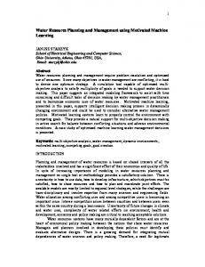
• Pipe-Size(p, t, k) denote the size of a pipe p, in interval [kt, (k + 1)t), assuming a resizing period of t. • Link-Size(l, t) denote the maximal bandwidth reserved on link l over the entire day, that is, maxkΣp routed on l Pipe-Size(p, t, k). • Link-Size(l, 24) denote the maximal bandwidth reserved on link l when the resizing period equal to the whole day (t = 24 hr). This is the capacity needed on the link if pipes were provisioned with a fixed capacity and never resized during a day. • Link-Size(l, 0) denote the maximal bandwidth reserved on link l when the resizing period is extremely small. Link-Size(l, 0) is therefore just the maximal number of calls in progress on link l during the entire duration of the simulation. ■ Figure 8. AT&T WorldNet backbone topology. Let Gain(l, t) = Link-Size(l, 24)/Link-Size(l, t), measure the capacity savings on link l due to pipe resizing with period t. Finally, define Gain(t) as Σl Link-Size(l, 4.5 24)/Σ l Link-Size(l, t), to measure the networkwide capacity Link bandwidth 4 gain due to pipe resizing. Gain(0) represents the capacity sav1.95*x ings that would be achieved if pipes were resized for every 3.5 call. Thus, comparing Gain(t) to Gain(0) is interesting and useful. 3 Figure 9 plots the link capacity required without resizing 2.5 (Link-Size(l, 24)) versus the link capacity required with resizing every 5 min (Link-Size(l, 5/1440)), for all links l, for a typi2 cal simulation run (September 28, 1998). Note that the gain is 1.5 fairly uniformly about 2 across all links. Thus, resizing pipes once every 5 min saves a factor of about two in capacity on all 1 links. In a large backbone network, this represents enormous 0.5 capital savings on transmission facilities. Figure 10 depicts the value of Gain(t) as a function of the 0 resizing period t for five weekdays. The maximal gain, Gain(0), 1 1.2 1.4 1.6 1.8 2 0.2 0.4 0.6 0.8 appears to be about 2.5. Again, for a resizing period of about Link capacity with resizing every 5 min 5 min, the gain is near 2 for all five days. We searched the data set for days whose results contradict ■ Figure 9. Link capacities required with and without pipe resizing. Fig. 10, but were unable to find any such results, or even any significant variation. For example, on August 31, 1998, the U.S. stock market dropped, and although the peak call volsavings are lower because there is less potential for statistical ume increased by 20 percent, the results (i.e., the gains) did multiplexing across pipes. not change. Weekend data shows essentially the same results, The use of pipe resizing requires backbone routers to interalthough the variability is slightly greater and the usage volpret signaling messages. In our experiments the total signaling umes somewhat less. traffic for the entire network generated due to pipe resizing is There are two possible explanations for why pipe resizing on the order of a few hundred messages per second, assuming provides such large capacity gains. One possibility is that a resizing interval of 5 min. In contrast, in a busy hour in the deterministic time-of-day fluctuation in the calling loads in difAT&T switched network, calls arrive at a rate of about 10 milferent geographical areas causes each of the pipes routed over lion calls/hr, generating total signaling traffic on the order of a a given link to hit its maximal load at different times during few thousand messages per second. We could reduce signaling the day. The second possibility is that due to the normal staload even further without sacrificing much in terms of effitistical fluctuations in the call arrival process, the aggregate ciency by resizing pipes with larger capacities less frequently. capacity required for a pipe varies over time. Pipe resizing can Putting it all together, the pipe resizing technique, operatprovide capacity gains due to either kind of traffic fluctuation ing on the timescale of a few minutes, successfully exploits since it allows better multiplexing of the link capacity between aggregation and statistical multiplexing, with attendant benepipes. Analysis of the simulation results reveals that at particfits in scalability and capacity savings: ularly busy periods (e.g., 4:00 p.m. EST), all 42 links are very • Capacity needs are comparable to those of networks that close to their daily peaks (this is not surprising since both use per-flow resource management in the backbone. coasts are in the midst of the workday at 4:00 PM EST). Thus, • Signaling overheads are negligible. the dominant reason for the effectiveness of pipe resizing appears to be statistical fluctuations. In our experiments there are 168 area codes, and therefore Conclusions about 30,000 pipes are being multiplexed on 42 (unidirectional) links. In related work, we have examined the effectiveness Building a robust IP-based telephony service requires coordinaof pipe resizing when the degree of traffic aggregation is tion of call signaling and resource management. The Distributed much greater (i.e., there are a much small number of pipes). Open Signaling Architecture incorporates explicit coordination These results suggest that pipe resizing is still useful as the between the call-signaling and the resource-management protodegree of traffic aggregation increases. However, the capacity cols to ensure that users are authenticated and authorized
IEEE Network • May/June 1999
31
2.4 8/31/98 (Mon) 9/18/98 (Fri) 9/25/98 (Fri) 9/28/98 (Mon) 9/29/98 (Tue)
2.2
Gain
2 1.8 1.6 1.4 1.2
Additional Reading
1 0
20
40
60
80 100 120 140 160 180 Time (min)
■ Figure 10. Gain(t) for various values of t.
before receiving access to the enhanced QoS associated with telephony service. This coordination also ensures that the semantics of traditional telephony service are met; specifically, the network verifies that resources are available end to end before the called user’s phone is allowed to ring, and the charges for network-layer resources begin only when the called party picks up. DOSA allows services and features to be implemented by intelligent end terminals, while allowing a service provider to add value as a trusted intermediary or through other network-based functionality, such as conference bridging. Providing a high-quality telephony service that meets stringent bounds on end-to-end packet delay, jitter, and loss requires adequate capacity along the end-to-end path for a voice flow. These functions have traditionally been implemented in the PSTN using per-flow hop-by-hop signaling. In this article we investigate a more scalable alternative involving per-flow signaling and admission control near the edge of the network, and signaling and admission control for aggregate flows in the core of the network. We analyze the performance of two scheduling algorithms, class-based priority and WF 2 Q+, to quantify the ability of IP routers to provide bounded queuing delay when using only a single FIFO queue for all voice packets. Our results suggest the need either to use priority scheduling for the voice class or to give it a large weight when using WF2Q+ scheduling. Our performance results demonstrate that aggregation does not adversely effect the efficiency with which network capacity is utilized. Trace-driven call-by-call simulations using data from the AT&T switched network demonstrate that the pipe resizing technique proposed in this article, operating on the timescale of a few minutes, successfully exploits aggregation and statistical multiplexing, with attendant benefits in scalability and capacity savings. In summary, we have presented an integrated framework for scalable call signaling and resource management to support IP telephony.
References [1] H. Schulzrinne and J. Rosenberg, “A Comparison of SIP and H.323 for Internet Telephony,” Proc. NOSSDAV ’98. [2] M. Arango et al., “Media Gateway Control Protocol,” Internet draft, , Nov. 1998. [3] M. Handley et al., “SIP: session initiation protocol,” IETF RFC 2543, Mar. 1999.
32
[4] K. Nichols et al., “Definition of the Differentiated Services Field (DS Field) in the IPv4 and IPv6 Headers,” RFC 2474, Dec.1998. [5] R. Callon et al., “A Framework for Multiprotocol Label Switching,” Internet draft, < draft-ietf-mpls-framework-02.txt>, Nov. 1997; work in Progress. [6] A. Lauck, C. Kalmanek, and K. K. Ramakrishnan, “SUBMARINE: An Architecture for IP Routing over Large NBMA Networks,” to appear, Proc. IEEE INFOCOM 1999. [7] R. Guerin, S. Blake, and S. Herzog, “Aggregating RSVP-based QOS requests,” Internet draft, Feb. 1998. [8] V. Jacobson, K. Nichols, and K. Poduri. “An Expedited Forwarding PHB,” Internet draft, , Jan. 1999. [9] J. C. R. Bennett and H. Zhang, “Hierarchical Packet Fair Queuing Algorithms,” Proc. SIGCOMM ’96, Aug. 1996, pp. 143–56.
[1] G. Hjalmtysson and K. K. Ramakrishnan, “UNITE: An Architecture for Lightweight Signaling in ATM Networks,” Proc. INFOCOM 1998.
Biographies Pawan Goyal (
[email protected]) received his Ph.D. in computer sciences from the University of Texas at Austin. His research interests are in computer networks, multimedia systems, operating systems, and distributed systems. He has received several awards for academic excellence, including the IBM Doctoral Fellowship. After working at AT&T Laboratories — Research for more than a year, he joined Ensim Corporation (a Silicon Valley startup). ALBERT GREENBERG’S (
[email protected]) biography was unavailable when this issue went to press. CHARLES R. KALMANEK (
[email protected]) received a B.S. degree in applied physics from Cornell University in 1980, an M.S. degree in electrical engineering from Columbia University in 1981, and an M.S. degree in computer science from New York University in 1988. He is currently division manager of networking research in AT&T Laboratories. His research interests include network architecture, protocol design, quality of service, and multimedia systems. Recently, he has been working on cable access networks and Internet telephony. WILLIAM T. MARSHALL (
[email protected]) received a B.S. degree in mathematics from Carnegie Mellon University in 1974, and a Ph.D. degree in computer engineering from Case Western Reserve University in 1979. From 1978 to 1979 he was assistant professor of computer engineering at CWRU. He joined AT&T Bell Laboratories in 1979, and is now a technology consultant in the Networking and Distributed Systems Research Center of AT&T Laboratories. His activities and research interests include all aspects of data communication networks, analytic modeling and performance measurement, and operating system design. PARTHO MISHRA (
[email protected]) received a B.Tech. degree from the Indian Institute of Technology, Kharagpur, in 1988, and M.S. and Ph.D. degrees from the University of Maryland in 1991 and 1993, all in computer science. He is currently a principal member of technical staff in the Networking and Distributed System Research Center at AT&T Laboratories-Research. His research interests include traffic management, wireless networking, and packet telephony and video services. His home page is at http://www.research.att.com/info/partho. DOUG NORTZ (
[email protected]) is district manager of the Local IP Services Architecture group at AT&T. Since joining AT&T in 1997, he has been leading systems engineering teams investigating AT&T ventures into local telephone service over cable systems. In 1998 he began working on IP-based telephony over cable systems, developing service, architecture, and signaling definitions. Before joining AT&T, he worked for eight years at Bellcore consulting on broadband architecture and service development. He earned an M.S. in information networking from Carnegie Mellon University and a B.S. in electrical engineering from Cornell University. K. K. RAMAKRISHNAN (
[email protected]) is a technology leader in AT&T Laboratories-Research, Florham Park, New Jersey. He got his Ph.D. in computer science from the University of Maryland in 1983. He was with Digital Equipment Corporation until 1994, where he was a consulting engineer. His research interests are in the design and performance of protocols and algorithms for computer networks and distributed systems. He is an editor for IEEE/ACM Transactions on Networking and IEEE Network, and is on the editorial board for Computer Communications Journal. He is a member of the End-End Research Group as part of the Internet Research Task Force, and participates in the IETF and ATM Forum. He has worked and published papers in the areas of congestion control and avoidance, local area networks and ATM, distributed systems performance, packet telephony, and issues relating to network I/O.
IEEE Network • May/June 1999