August 14, 2008 15:37
9.75in x 6.5in
b688-ch13
1st Reading
Chapter 13
Integration of RFID and Wireless Sensor Networks
Hai Liu,∗ Miodrag Bolic,† Amiya Nayak‡ and Ivan Stojmenovi§ ∗,†,‡,§
SITE, University of Ottawa, Ottawa, K1N 6N5, Canada § EECE, The University of Birmingham Birmingham, B15 2TT, United Kingdom ∗
[email protected] †
[email protected] ‡
[email protected] §
[email protected]
Radio frequency identification (RFID) and wireless sensor networks (WSN) are two important wireless technologies that have a wide variety of applications and provide limitless future potentials. RFID facilitates detection and identification of objects that are not easily detectable or distinguishable by using current sensor technologies. However, it does not provide information about the condition of the objects it detects. Sensors, on the other hand, provide information about the condition of the objects as well as the environment. Hence, integration of these technologies will expand their overall functionality and capacity. This chapter first presents a brief introduction on RFID and then investigates recent research works, new patents, academic products and applications that integrate RFID with sensor networks. Four types of integration are discussed: (1) integrating tags with sensors; (2) integrating tags with wireless sensor nodes and wireless devices; (3) integrating readers with wireless sensor nodes and wireless devices; and (4) mix of RFID and wireless sensor networks. New challenges and future works are discussed at the end.
Keywords: RFID; wireless sensor networks; integration; survey; applications; products; patents.
13.1.
Introduction
RFID is a means of storing and retrieving data through electromagnetic transmission using an RF compatible integrated circuit.7 It is usually used to label and 1
August 14, 2008 15:37
2
9.75in x 6.5in
b688-ch13
1st Reading
H. Liu et al.
track items in supermarkets and manufactories. For example, Wal-Mart, Procter and Gamble, and the US Department of Defense have deployed RFID systems with their supply chains.20 However, the potential of RFID is much more than this. Today, RFID has been widely applied in supply chain tracking, retail stock management, library books tracking, parking access control, marathon races, airline luggage tracking, electronic security keys, toll collection, theft prevention, and healthcare.39 Current trends and forecasts indicate that the market will grow fast in the next 10 years. In 2006 alone, 1.02 billion RFID tags were sold.13 The total value of the market, including hardware, systems and services, is expected to grow from 500 million to 7 billion by 2016.11 Briefly, RFID systems consist of two main components: Tags and readers. A tag has an identification (ID) number and a memory that stores additional data such as manufacturer name, product type, and environmental factors such as temperature, humidity, etc. The reader is able to read and/or write data to tags via wireless transmissions. There are basically two types of communications between tags and readers. One is inductive coupling, which is done by antenna structures forming an integral feature in both tags and readers. The other is propagation coupling, which is done by propagating electromagnetic waves.7 In a typical RFID application, tags are attached or embedded in objects that need to be identified or tracked. By reading tag IDs in the neighborhood and then consulting a background database that provides mapping between IDs and objects, the reader is able to monitor the existence of the corresponding objects.37 A sensor network is composed of a large number of sensor nodes that can be deployed on the ground, in the air, in vehicles, inside buildings or even on bodies. Sensor networks are widely employed in environment monitoring, biomedical observation, surveillance, security, etc.4 Since sensors’ energy cannot support long range communication to reach a sink, which is generally far away from the data source, multi-hop wireless connectivity is required to forward data to the remote sink. WSNs are different from RFID networks. WSNs are usually employed to monitor objects in interest areas or to sense environments while RFID systems are used to detect presence and location of objects which have RFID tags. In typical applications, relay nodes are deployed to forward data from sensor nodes to remote sinks in WSNs. It forms a multiple hop network while traditional RFID is only single hop and consists of a batch of tags and several readers. Sensor nodes are more intelligent than RFID tags. Sensor nodes’ firmware can be easily reprogrammed which is not the case for RFID tags. RFID readers can be parameterized, but they are rarely user-programmed. Hence, RFID networks and WSNs represent two complementary technologies and there exist a number of advantages in merging these two technologies. Some of them include: adding ad-hoc capabilities to RFID network, adding sensing capabilities to RFID tags and adding tracking capabilities to RFID tagged objects that are difficult to detect otherwise.
August 14, 2008 15:37
9.75in x 6.5in
b688-ch13
Integration of RFID and Wireless Sensor Networks
1st Reading
3
The chapter investigates recent research works, new products/patents and applications that integrate RFID with wireless sensor networks. We classify current works into four categories according to manner of integration. They are (1) integrating RFID tags with sensors; (2) integrating RFID tags with wireless sensor nodes; (3) integrating RFID readers with wireless sensor nodes or wireless devices; and (4) mixing RFID systems and wireless sensor networks. The difference between class 1 and class 2 is that the tags with integrated sensors are traditional RFID tags which communicate with only readers, while the tags in class 2 are able to communicate with each other and form a multiple hop network. The investigation starts with a brief introduction on RFID. Since WSNs have already been introduced in the book, we skip its introduction and focus only on RFID in rest of this section.
13.1.1.
Previous work
Surveys and classifications on the integration of RFID and wireless sensor network technologies are attempted in several publications but they either are outdated or are missing a comprehensive study. In Ref. 41, three types of integrations are suggested. The first one is heterogeneous network architecture with a mix of RFID tags and WSN nodes and a smart station that will be used for collecting information from two networks. The second type of integration includes integration of the reader and a WSN node in one device. The third type is a smart active tag that merges functionality of a WSN node and an active tag. These three classes are similar to our classes 4, 3 and 2, respectively. However, in this chapter we will perform a comprehensive study of many current and potential solutions that correspond to these classes and not only point out specific solutions as described in Ref. 41. Besides, there are some serious flaws in the proposed architectures of Ref. 41. For example, a smart station is based on a single reader with multiple antennas. However, the cable between the reader and the antennas have to be short in practical implementations so that such a solution with a single reader is not feasible when there is a need to cover relatively large areas where both RFID and WSN units operate. In Ref. 26, several different classifications are presented. This paper describes possible ways of integrating WSNs into the existing RFID network based on the standards defined by EPCGlobal (www.epcglobal.org). The paper is different from this book chapter because: (1) it considers only integration of WSNs into RFID frameworks, and (2) on the RFID side, it considers only the EPCGlobal-based RFID technologies. However, a number of useful classifications and architectures are defined. RFID tags with added sensors are classified as fixed and variable function sensor tags. Fixed function sensor tags are black boxes that have pre-defined functionality. Variable function sensor tags can change their function by changing for example the air protocol. At the level of integration, four reference models for integration are proposed. They include (1) mix of RFID and WSN with the integration at the application level, (2) mix of RFID and WSN with the integration at the
August 14, 2008 15:37
9.75in x 6.5in
b688-ch13
1st Reading
H. Liu et al.
4
filter and collection level (this level in the EPC framework is intended for providing useful non-redundant data to upper levels), (3) hardware integration in which the RFID reader is responsible for collecting data from both tags and WSNs, and (4) logical integration at the EPCIS level that allows for a mix of RFID and WSNs. In Ref. 6, the taxonomy of wireless sensor network devices that includes RFID devices is proposed. Attributes for characterization of wireless devices include (1) communication, (2) power, (3) memory, (4) sensors, and (5) other features. The paper does not consider integration of devices but it gives a uniform classification that can be applied to integrated WSN and RFID devices. Each attribute is further divided into a set of sub-attributes so that fine classification of wireless devices is possible. Communication attributes are divided into communication protocols/standards, communication modes, communication modules and supports for mobility. Communication modes are “device talk first”, “beacon”, “ad hoc” and “human controlled”. Power is further classified into three categories: “storage”, “energy harvesting mechanisms” and “transfer”. Storage uses batteries or passive devices such as capacitors. Energy transfer is the way by which passive RF devices are powered. The energy transfer mechanisms are inductive coupling, capacitive coupling, and passive backscattering. Memory can be classified into read-only, write-once and read-write.
13.1.2.
RFID technology
13.1.2.1. Types of RFID tags Based on power source, RFID tags can be classified into three major categories: active tags, passive tags, andsemi-passive (semi-active) tags. An active tag contains both a radio transceiver and a battery that is used to power the transceiver. A passive tag reflects the RF signal transmitted to it from a reader or a transceiver and adds information by modulating the reflected signal. The passive tag does not use any battery to boost the energy of the reflected signal.7 Every passive tag contains an antenna needed to collect electromagnetic energy in order to wake up the tag and to reflect (backscatter) the portion of the energy back to the reader. In addition, tags have transmitter/receiver circuits, power generating circuits and the state machine logic. The state machine logic is needed in order to follow the RFID protocol and support communication between the reader and tags. Similar to passive tags, semi-passive tags use the radio waves of senders as an energy source for their transmissions. However, a semi-passive tag may be equipped with batteries to maintain memory in the tags or power some additional functions. Active tags are more powerful than passive tags/semi-passive tags. For example, they have larger range/memory and more functions. However, they are also more expensive than passive/semi-passive tags. Based on memory type, RFID tags can also be classified into two categories: tags with read/write memory, and tags with read-only memory. As their names
August 14, 2008 15:37
9.75in x 6.5in
b688-ch13
Integration of RFID and Wireless Sensor Networks
1st Reading
5
imply, the tags with read/write memory allow both read and write operations on the memory while data in the tags with read-only memory cannot be modified after the manufacturing process. The tags with read/write memory are more expensive than the tags with read-only memory. 13.1.2.2. Radio frequency RFID tags operate in three frequency ranges: low frequency (LF, 30–500 kHz), high frequency (HF, 10–15 MHz), and ultra high frequency (UHF, 850–950 MHz, 2.4–2.5 GHz, 5.8 GHz).20 LF tags are less affected by the presence of fluids or metals when compared to the higher frequency tags. They are fast enough for most applications and are also cheaper than any of the higher frequency tags. However, low frequency tags have shorter reading ranges and low reading speeds. Typical applications of LF tags are access control, animal identification and inventory control. The most common frequencies used for LF tags are 125–134.2 kHz and 140–148.5 kHz. HF tags have medium transmission rates and ranges but are more expensive than LF tags. Typical applications of HF tags are access control and smart cards. RFID smart cards, working at 13.56 MHz, are the most common members of this group. UHF tags have the highest transmission rates and ranges among all tags. They range from 3 to 6 meters for passive tags and more than 30 meters for active tags. The high transmission rates of UHF tags allow the reading of a single tag in a very short time. This feature is important in the application where tagged objects move very fast and remain within a reader’s range only for a short time. However, UHF tags are severely affected by fluids and metals. These properties make the UHF tags most appropriate in automated toll collection systems and railroad car monitoring systems. UHF tags are more expensive than any other tag. The typical frequency of UHF tags are 868 MHz (Europe), 915 MHz (USA), 950 MHz (Japan), and 2.45 GHz. Frequencies of LF and HF tags are license exempt and can be used worldwide while frequencies of UHF tags require a permit and differ from country to country.
13.1.3.
Motivation of integration of RFID and WSNs
13.1.3.1. Applications of RFID and WSNs The major application of RFID networks is to detect the presence of tagged objects and/or people. Another important application of RFID systems is to provide the location of the objects. We distinguish among several different approaches for providing the location: detecting position of the object with the mobile reader based on detection of tags placed at fixed known locations and detection of position of the object with tags based on the position of fixed readers. In case of long-range RFID systems, the estimation of the position of RFID tags can be further improved by using triangulation and/or signal processing techniques.
August 14, 2008 15:37
6
9.75in x 6.5in
b688-ch13
1st Reading
H. Liu et al.
WSNs are mainly used for sensing the environment, positioning and identifying objects/people. WSNs are used for sensing temperature, humidity, pressure, vibration intensity, sound intensity, power-line voltage, chemical concentrations, pollutant levels, etc. WSNs can be used for sensing the environment, or sensing phenomena related to objects or people when sensors are attached to them. By combining the properties of RFID (identifying and positioning) and WSNs (sensing, identifying and positioning) we can define four different application scenarios for combining RFID and WSNs. Some of them are used much more in industry and academia then others. In addition, WSN nodes can be independent or attached to objects/people. Some examples of integration at the application level are provided next: (1) Integration in which RFID is used for identifying and WSN for sensing. (a) WSN and RFID are attached to the same object. In the type, RFID tags and integrated sensors are attached to the same object to perform both detecting and sensing task. The tags are used to detect presence of the objects and the integrated sensors are used to sense the objects’ temperature,22 PH value,8 vibration,5 angular tilt,31 blood pressure and heartbeat rate,14 etc. In some applications, integrating RFID readers with wireless devices and wireless sensor nodes, the integrated sensor provide both sensing and communication functionalities, such as Refs. 19 and 27. (b) RFID tag is attached to the object and WSN is used for sensing the object. An example of this type of application is using RFID tags to provide information about the object that were photographed in museums. Here, the reader is integrated to the camera and tags are attached to the objects in the museum. After the object is sensed, RFID can provide additional information about the object. (c) RFID tag is attached to the objects and WSN is used for sensing the environment. Typical applications includes mobile robots that rely on RFID for detecting non-sensible objects and on WSN for collecting information about temperature, humidity and other environment-related information. (2) Integration in which RFID is used for identifying objects/people together with sensors. An interesting solution is from Broadcom (http://www.broadcom.com), in which RFID information can be read from the tag only after the fingerprint scan matches the one that is already stored in the chip. In this way sensor and RFID technology can be combined to enhance security. (3) Integration in which RFID is used for identifying objects/people and WSN is used for providing location.
August 14, 2008 15:37
9.75in x 6.5in
b688-ch13
Integration of RFID and Wireless Sensor Networks Table 13.1
7
Difference between RFID and WSN.
Wireless sensor networks
RFID systems Detect presence and location of tagged objects
Component Protocols Communication Mobility
Sense interested parameters in environments and attached objects Sensor nodes, relay nodes, sinks Zigbee, Wi-Fi Multi-hop Sensor nodes are usually static
Programmability Price
Programmable Sensor node — medium
Deployment
Random or fixed
Purpose
1st Reading
Tags, readers RFID standard Single hop Tags move with attached objects Usually closed systems Reader-expensive Tag-cheap Fixed
In Ref. 10, RFID tags are used for identifying people in the museum tour and WSN is used to locate the leader of the group. After the locations of the leaders of a group are known, the lost members are guided in finding their group leaders. (4) Integration in which RFID is used to assist positioning that is identified using sensors. In Ref. 25, a positioning system for first responders is described in which different sensors are used to estimate the position of first responders and RFID tags placed at known positions are used to correct the estimated position. 13.1.3.2. Difference between RFID and WSN Technologies In this section, we will point out the major differences between RFID and WNS technologies. The major components of WSNs are sensor nodes. Besides sensor nodes, the network can contain relays, sinks and some other nodes. Communication among the nodes is multi-hop. On the other side, classical RFID systems are composed of RFID tags and readers. Since the price and power consumption of the tags is a very important issue, most of the complexity is transferred to the reader side. Communication between the reader and the tags is single-hop. Standardization efforts in RFID networks are significant. There is a large interest and large investments in RFID in industry and hence a number of standards. Major standardization organizations are EPCGlobal and ISO. Both organizations define a set of standards that can be divided into data and interface standards. Data related standards define the format of the identification number. Interface standards define protocols between the different levels of the stack including both reader-totag communications as well as the interface among different software layers. This is very different from the existing trends in WSNs where there is much less industrial involvement. WSNs usually rely on existing standards borrowed from other areas.
August 14, 2008 15:37
8
9.75in x 6.5in
b688-ch13
1st Reading
H. Liu et al.
Existing protocols such as Zigbee are accepted in general — however there are many solutions that are proprietary or based on different standards. Deployment of WSN nodes can be both random and fixed. On the other hand, if we consider long range RFID readers, the position of RFID antennas must be computed carefully in order to cover all the tags in the range as well as to prevent interference. Several types of interferences exist in RFID networks. They include tag-to-tag, reader-to-tag and reader-to-reader interference. Tag-to-tag interference occurs if several tags try to communicate with the same reader at the same time. Reader-to-tag interference occurs if the tag receives signals from two readers. Tags are not frequency selective and they can get confused in that case. Reader-to-reader interference means that the signal from the neighboring readers will be stronger than the backscattered signals from the tags. There are several standards that deal with tag-to-tag interference. The EPC Class 1 Generation 2 UHF standard16 is based on slotted Aloha reader-to-tag communication protocol. The collision occurs if several tags select the same time slot for communication. The reader is responsible for running the optimization algorithm that will minimize the query time (throughput). The same standard16 suggests solutions for reader-to-reader and reader-to-tag interference based on separating reader and tag transmissions spectrally or temporarily. Hence, RFID readers are deployed at fixed positions. Functionality of RFID tags is usually fixed. Since the main goals in designing RFID tags are to lower power consumption and lower cost, tags are usually implemented in hardware. RFID readers are usually black boxes without possibility of firmware modification. On the other side, in many WSN nodes microcontrollers are reprogrammable. This enables easier modifications and facilitates research on WSNs. Since the difference between WSNs and RFID technologies are significant, their integration would enable the combination of both their merits. WSNs offer a number of advantages over traditional RFID implementations such as multi-hop communication, sensing capabilities and programmable sensor nodes. On the other hand, WSNs are also required to be integrated with RFID. First, RFID tags are much cheaper than wireless sensor nodes. In some WSN applications it is an economical solution to utilize RFID tags instead of wireless sensor nodes. This is true in objects in which we care only for their presence and locations. Second, integration with RFID equips sensor nodes with tag IDs. One may say that the MAC address of a sensor node can be treated and utilized as an ID. Note that RFID is a mature technology of storing and retrieving data, and has been widely used in manufactures and retailers. Use of tag IDs instead of MAC addresses is an efficient solution for wireless sensor nodes. Moreover, although RFID technology has limitations such as low tolerance to fluid or metal environments, it can extend the ability of a sensor network by providing sensible properties to otherwise un-sensible objects. For instance, sensor nodes may fail to work in harsh environments or some special applications and RFID could be an alternative solution.
August 14, 2008 15:37
9.75in x 6.5in
b688-ch13
Integration of RFID and Wireless Sensor Networks
1st Reading
9
These two technologies have almost converged in long-range active RFID tag solutions. They can be implemented using RFID protocols or some other widely accepted standards such as WLAN. They have the unique ID numbers like RFID tags and they are usually attached to one or more sensors and as such they represent a sensor node. In some solutions, MAC addresses are used as an RFID tag.
13.2.
Integrating RFID Tags with Sensors
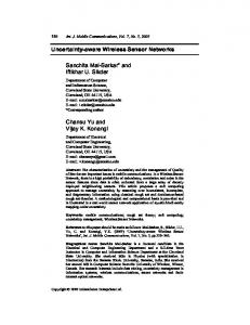
Integration of this class is used to equip RFID tags with sensors which provide sensing capabilities for RFID tags. The RFID tags with sensors (sensor-tags) use the same RFID protocols and mechanisms for reading tag IDs as well as for collecting sensed data. For example, the Class 1 Generation 2 UHF protocol from EPCGlobal16 allows the specification of which part of the tag’s memory is used for reading. Thus, sensed data can be selected and read by EPC Generation 2 compliant readers by using properly configured commands. Since integrated sensors inside RFID tags are used for only sensing purposes, current protocols of these RFID tags rely on singlehop communication. That is, integration of this class is typical in RFID systems with additional sensing abilities for integrated tags. A distributed architecture for ubiquitous RFID sensing networks is studied in Refs. 30 and 35. RFID tagged objects communicate an EPC code to identify themselves as a unique entity. Integrated sensors in the tags are used to sense the objects and environments. The Analog signal of the sensors is converted by the A/D module and the resulting data is forwarded by readers to the base station which provides service layer functionalities. Readers are able to detect certain events or query objects with certain RFID labels to obtain event data. The application system then responds to these events and corresponding actions are processed. The system architecture is shown in Fig. 13.1. Current RFID sensing applications include monitoring physical parameters, automatically detecting product tampers, detecting harmful agents, and noninvasive monitoring.38 A large portion of applications are used to monitor the temperature of tagged objects and environments. There are several commercial RFID tags with integrated sensors. Based on the way the tags are powered up, they can be classified into passive tags, semi-passive tags and active tags. Three representative classes are introduced below. Sensor
Tag Reader
Sensor
Tag
Sensor
Tag Fig. 13.1.
Base Station Reader System architecture.
August 14, 2008 15:37
10
13.2.1.
9.75in x 6.5in
b688-ch13
1st Reading
H. Liu et al.
Passive tags with integrated sensors
Since integrated sensors are usually powered by additional batteries, most tags with integrated sensors are semi-passive or active tags which are battery powered. However, there exist some passive tags with integrated sensors which operate without a battery and instead gather power from the RF signal of readers. Passive tags with integrated sensors are used in the following applications: temperature sensing and monitoring,12,23 PH value detection,8 and photo detection.12 We describe several solutions below. Instrumental passive tags developed by Instrumentel Ltd. (http://www. instrumentel.com) are capable of powering sensors and actuating switches as well as holding data. The tags capture enough power from reader signals to drive integrated sensors. Unlike the sensors in an active tag, the sensor in an Instrumentel tag monitors the environment only when it is interrogated by a reader. It operates in 13.56 MHz and is able to provide a reading range of up to 200 millimeters (8 inches), which is longer than the range of many other 13.56 MHz passive RFID tags currently available. The size of an Instrumentel tag is about 20 mm by 10 mm. Its price is expected to be below 5 pounds each.8 In one of its applications, an Instrumentel tag with a PH sensor is placed into dentures and is used to monitor the level of acidity or alkalinity of food in the mouth of test patients. Using its technology’s ability to actuate switches, an Instrumentel tag can also be integrated with a locking mechanism, so that it can be applied to containers to secure goods throughout the supply chain. In the application, a smart container includes an Instrumentel tag which is able to store data and lock/unlock the container using a reader signal. The technology is suited to a range of applications, including securing police evidence and medical specimens. Besides industrial products, there are some academic solutions. An RF-powered RFID tag with temperature and photo sensors is studied and designed in Ref. 12. It consists of a supply voltage generator, a temperature-compensated ring oscillator, a synchronizer, a temperature sensor and a photo sensor. The tag gathers power from external ISM (860–960 MHz) band RF signals and senses ambient temperature and light. It operates in three states: ready, interrogating and active. The tag enters ready state when it receives an energizing RF signal. In ready state, only the internal clock generator is activated. The tag enters interrogating state when the base station sends a request to it. In interrogating state, the demodulator and decoder are activated to enable one of two sensors. When the selected functional block is activated, the tag enters active state and requested data is transmitted to the base station. It automatically switches to ready state after active state. The tag is fabricated in a 0.25-µm CMOS process. The chip size is 0.6 mm × 0.7 mm excluding pads and the total power consumption is 5.14 µW when in the active state. A solution for long range passive RFID tags is proposed in Ref. 23. It consists of a divided micro-strip antenna and a rectifying circuit which is used to boost the DC voltage. Two passive tags are implemented. The tag working at 860–950 MHz
August 14, 2008 15:37
9.75in x 6.5in
b688-ch13
Integration of RFID and Wireless Sensor Networks
1st Reading
11
achieves a 30 m read range. The tag working at 2.45 GHz is integrated with a temperature sensor. Its range is longer than 9 m. The tags have sizes of 90 × 60 × 4 mm and 60 × 25 × 4 mm for 900 MHz and 2.45 GHz, respectively. 13.2.2.
Semi-passive tags with integrated sensors
Semi-passive tags with integrated sensors are used in the following applications: temperature sensing and monitoring,22,32 location recording,32 vehicle-asset tracking,1 and access control. Next, we describe industrial solutions. KSW — TempSens developed by KSW Microtec AG (http://www.kswmicrotec.de/) is able to periodically measure temperature in a configurable measurement interval. It is a semi-passive tag and can be attached to/embedded in any product that could spoil during transport due to temperature fluctuations. For example, it can be attached to frozen chickens that have a risk of salmonella contamination if the temperature of the environment becomes too high for a long time. The main features of KSW — TempSens are shown in Table 13.2.22 ThermAssureRF developed by Syntax Commerce (http://www. syntaxcommerce.com) is a semi-passive tag which is able to monitor cold chain and temperature fluctuations over time during shipment and storage of temperature sensitive goods. It is credit card size and is able to record both temperature and location information. ThermAssureRF is also capable of receiving programmable thresholds through the software application. It can be used for tracking inventory throughout the entire facility. The main features of ThermAssureRF are shown in Table 13.3.22 Table 13.2
Main features of KSW — TempSens.
Operating model
Semi-passive
Operating frequency Operating temperature Operating voltage Security Memory Storable values Memory access Sampling interval
13.56 MHz (HF) −15◦ C to +50◦ C 3V 6 Byte Code 2 Kbit SRAM, 4 Blocks of 256 Byte each, configurable 64 time and temperature values storable Read/write 10 seconds to 16 hours (configurable)
Table 13.3
Main features of ThermAssureRF.
Operating model
Semi-passive
Operating frequency Operating temperature Accuracy Memory Setting
13.56 MHz (HF) −40◦ C to +50◦ C +/ − 0.2◦ C 4000 readings Programmable alarms, programmable reading intervals
August 14, 2008 15:37
12
9.75in x 6.5in
b688-ch13
1st Reading
H. Liu et al.
The Alien Technology Battery Power Backscatter 2450 MHz system developed by Alien Technology (http://www.alientechnology.com/) is an extendable solution to fill the gap between short-range passive systems and high-cost active systems. The tag of the system is easily extendable so that many different types of sensors can be connected to it through a serial I2C bus. The tag provides reliable read/write capabilities with a range of up to 30 m. It can be applied in long range identification, sensor monitoring, vehicle-asset tracking, etc. Equipped with a small battery, the tag is able to store 4 Kbytes of data which includes locally acquired sensor data. It works in 2450 MHz frequency range and there is an onboard temperature sensor. The tags can be attached to temperature-sensitive products at production or shipment time, and the temperature history of the product can be downloaded wirelessly at the final destination or at any point along the way. The low power backscatter technology is employed and therefore a small battery can provide several years of operation.1 Another interesting solution that allows for integration with external sensors is Enterprise Dot from Axcess Inc (http://www.axcessinc.com/). Dot technology incorporates a battery powered and software definable wireless transceiver that is compatible with multiple global regulations, including EPC Class 1 and Gen 2 standards. It has three radios on the same chip and 3 antennas: UHF 315/433 MHz range in which it acts as an active tag, UHF 900 MHz range for EPC based applications in which it acts as a passive tag and LF 100–150 kHz range. The chip also has an external connection through an I2C bus. Dot supports a range of applications including manufacturing, the enterprise, oil and gas, utilities, education, government and the military. It is a good solution for access control badges, passive RFID product tags, active RFID asset tags, real time location systems (RTLS) and distributed sensor transmitters.
13.2.3.
Active tags with integrated sensors
Active tags with integrated sensors are used in the following applications: temperature sensing and monitoring,3 vibration detection,5 blood pressure and heartbeat rate monitoring, etc.14 Next we describe industrial and academic solutions. Log-ic Temperature Tracker developed by American Thermal Instruments (www.americanthermal.com/) is an active tag. It acts as a watchdog in temperatureregulated or temperature-sensitive environments. The Log-ic Temperature Tracking system consists of three components: Log-ic Temperature Tracking Tags, a CertiScan RFID Reader and CertiScan Log-ic Software which runs on a standard windows based PC or laptop. The Log-ic Temperature Tracking tag is capable of receiving programmable temperature thresholds via 2-way RFID communication. The LED indicator on the tag can blink with warning signals if temperature exceeds the thresholds. The main features of the Log-ic Temperature Tracker are shown in Table 13.4.3
August 14, 2008 15:37
9.75in x 6.5in
b688-ch13
Integration of RFID and Wireless Sensor Networks Table 13.4 tracker.
1st Reading
13
Main features of Log-ic temperature
Operating model
Active
Operating frequency Operating temperature Accuracy Memory
13.56 MHz (HF) −40◦ C to +65◦ C +/ − 1.0◦ C Up to 64,000 readings
Table 13.5 Main features of 2.4 GHz vibration sensor tag. Operating model
Active
Operating frequency RFID sensors Min sensitivity Read range Data rate Power Battery life
2.45 GHz (UHF) vibration 4 V/g 0–100 m 1 Mbps 12∼18 µA, 3V 4 years
Bisa Technologies (http://www.bisatech.com/) is an active RFID products provider. It provides many active sensor tags which operate at 2.4 GHz–2.5 GHz. For example, the 2.4 GHz Temperature Sensor Tag (model No 24TAG02T) is capable of collecting real-time temperatures of tagged items as well as identifying and locating them. It also can set off an alarm if the detected temperature is beyond the reasonable temperature. The size of the tag is 90 × 31 × 11 mm. The reading range is up to 100 m and the reading rate is 100 tags per second. The lifetime is estimated to be 4 years with a 3V battery. Typical applications of the tag include cold logistics and medicine transportation. Another active sensor tag from the company is 2.4 GHz Vibration Sensor Tag (model No 24TAG02V). It is able to detect and record tagged items’ either continuous or impulsive vibrations. So, it is applicable to various alarm systems. The main features of the tag are shown in Table 13.5.5 Besides the above industrial products, there are solutions presented by academia, such as. Ref. 14. Two different architectures for sensor-embedded RFID (SE-RFID) systems are proposed. The first architecture is illustrated in Fig. 13.2. In the architecture, multiple sensors with different functions can be embedded in a tag and these sensors are controlled by a programmable timer. The sensors sample external data independently and periodically. The obtained raw data are preliminarily processed by the microprocessor before sending to a more powerful database via the reader. The database integrates the data from the reader and from other sources such as user interventions and the Internet. The sampling of sensing data can be turned on/off and be programmed through the reader. Since the tags in the system need to be periodically turned on to sample data, they need to be battery-powered.
August 14, 2008 15:37
9.75in x 6.5in
b688-ch13
1st Reading
H. Liu et al.
14
Fig. 13.2.
Architecture I of SE-RFID systems.
Fig. 13.3.
Architecture II of SE-RFID systems.
Once the remaining energy of the tags is less than a particular unworkable level, the tags are able to automatically switch to passive mode. This means that the sensing function operates only when the tag is in the interrogative zone of the reader. In the second architecture shown in Fig. 13.3, each tag has only one integrated sensor. Similar to the first architecture, sensors in this architecture sample environment data periodically and independently and the sensing data is transmitted to the reader. Since the tag contains only one sensor and the microprocessor is embedded inside the reader, the tag in the second architecture consumes much less energy compared with that in the first architecture. Moreover, it allows different sensing sources to be located at different geographical positions. If different sensor sources are located at the same position, the first architecture is a better solution. To validate the proposed architectures, a real-time health monitoring system is further developed in Ref. 14. The SE-RFID system is able to continually monitor, re-evaluate and diagnose the medical condition of chronic patients. The sensor tag is installed within a convenient device, such as a watch, worn by the patient. Three different sensors for measuring temperature, blood pressure and heartbeat rate are adopted. The integrated sensors periodically sample the patient’s parameters and
August 14, 2008 15:37
9.75in x 6.5in
b688-ch13
Integration of RFID and Wireless Sensor Networks
1st Reading
15
then analyze the preliminary data. The sensing data are further processed by readers which are installed in the patient’s vehicle, office or home. The data will be transmitted to a doctor through the Internet. The sensor tag is also able to contact the reader to send an emergency signal directly to the doctor in emergency cases. Since the sensing sources, i.e., temperature, blood pressure and heartbeat rate, can be detected at the same position of the patient’s body, such as the patient’s wrist, the first architecture is a good solution for the real-time health monitoring system. The system operates at UHF 915 MHz. The SE-RFID reader is directly connected to a PC computer via a USB connection. The PC computer is further connected to the Internet via wireless LAN using Wi-Fi standard. This allows critical data to be stored in a remote database for future diagnoses.
13.3.
Integrating RFID Tags with Wireless Sensor Nodes and Wireless Devices
RFID tags integrated with sensors have limited communication capabilities. In highend applications, it is possible to integrate RFID tags with wireless sensor nodes and wireless devices, such that the integrated tags are able to communicate with many wireless devices which are not limited to readers. The main difference between the tags of this class and the tags discussed in Sec. 2 is that the tags with integrated sensors are traditional RFID tags which communicate only with readers, while the tags in this class are able to communicate with other wireless devices, including tags themselves. Therefore, the tags in this class are able to communicate with each other and form a multiple hop network. These new tags may be compliant with existing RFID standards or they can have proprietary protocols. CoBIs RFID tags9 are designed to monitor the ambient conditions around them and provide alerts when detected conditions break predetermined business rules. Each CoBIs tag carries an accelerometer (movement) sensor, a wireless transceiver, up to 10 kilobytes of memory and other computing components for storing and processing business rules. The tags are able to communicate with each other via a proprietary peer-to-peer protocol. Each node transmits not only its unique ID number but also details of its sensed data to all other nodes within a 3-meter range. These communications enable CoBIs tags to be tagged to chemical containers to monitor ambient parameters and total volume of stored chemicals. It will show alarm messages and take corresponding actions if the detected ambient parameters or total volume of chemicals exceed some predetermined threshold. The application requires communications not only between tags and readers, but also among tags for cooperative control on the total volume of chemicals. Moreover, it also helps ensure that potentially reactive chemicals have not been stored close to each other. AeroScout T3 Tags developed by AeroScout (http://www.aeroscout.com/) are Wi-Fi-based active RFID tags which utilize standard Wi-Fi networks to track highvalue assets and people in real time in both indoor and outdoor applications. There
August 14, 2008 15:37
16
9.75in x 6.5in
b688-ch13
1st Reading
H. Liu et al.
is a built-in motion sensor and an optional built-in temperature sensor. The tag is tamper proof and can periodically retrieve valuable data such as fuel gauge, mileage, or pressure measurements. Since it follows Wi-Fi standard, the generated data can be received and processed by any wireless access points (802.11b/g) from various networking vendors. This enables customers to have multiple reader options. The tag’s small size allows it to be attached to very small or oddly-shaped assets. AeroScout T3 offers multiple mounting options, such as a trailer mount, an ID badge clip and a vehicle hanger. Expanded LED functionality adds the option for up to three different colored LED lights on the tag when unique visual identification is needed in large inventory scenarios. The tag is equipped with a powerful and replaceable battery which provides up to 4 years operation. The battery level is periodically reported, so that replacement of the battery can be done efficiently. In Asia, multi-hop RFID tags had been developed by NTT labs (http:// www.nttcom.co.jp) to prevent monkeys/animals from messing up farms. These sensor tags are battery-powered and operate in 429MHz band. The communication range is less than 1km. The sensor tags not only can send out information, but also can read/relay information to other tags. Monkeys are first attached with tags that act as transmitters. The tags which are installed in the environment act as receivers and detect monkeys as they approach farms. The information will eventually be gathered at the RFID reader and be reported to residents. Since there is no wireless/network connectivity in mountains, some tags act as relay devices and are installed at key points. Actually, the tags in this class can be treated as wireless sensor nodes with RFID ability in some degree. A wireless smart sensor platform is studied in Ref. 31. It is capable of “plug-and-play” capability and uses RF links, such as Wi-Fi, Bluetooth, and RFID, for communications in a point-to-point topology. The platform consists of a collection of sensors, and actuators which communicate with the central control unit through standard RF links. Each sensor or actuator is equipped with a smart sensor interface (SSI). The interface extracts data from sensors, sends commands to the actuators, and provides a data communication interface to the central control unit. The sensor/actuator coupled with SSI is the smart sensor node. The architecture of the smart sensor node is shown in Fig. 13.4. The wireless smart sensor platform is further implemented to demonstrate its nondeterministic real-time performance. To achieve near real-time performance, the smart sensor node tracks the traffic of wireless channels and uses a simple TCPlike congestion control scheme to regulate the traffic. That is, it increases packets linearly in case of low load of the system and drops packets exponentially in case of heavy load. Once there is congestion, high traffic, or connection loss, the node turns to safe mode, and waits for reconnection of the central control unit or degradation of collision signals. The implemented system is a proportional gyro motor-encoder system. It consists of two smart sensor nodes and a laptop which acts as the central control unit.
August 14, 2008 15:37
9.75in x 6.5in
b688-ch13
Integration of RFID and Wireless Sensor Networks
Fig. 13.4.
1st Reading
17
Architecture of the smart sensor node.
Each sensor/actuator pair is connected to a SSI and uses Bluetooth to communicate with the central control unit. One smart sensor node combines a Bluetooth radio, a rate sensor and an RFID tag into a smart sensor board. The other smart sensor node integrates an actuator and a Wi-Fi radio into its smart sensor board. The gyro senses the angular tilt and communicates with the laptop which in turn sends appropriate commands to the motor. The encoder, attached to the motor, tracks the motor’s position. The safe mode of the system is used to bring the motor to a halt in this implementation. The smart sensor nodes monitor the status of a machine and store the health information in the RFID tag. The tag is used as a plain wireless non-line-of-sight data storage. One can retrieve the required health information of the machine by querying the tag with a handle RFID reader even when the central computer (laptop) has been switched off. In the implementation, ISO 15693 (13.56 MHz) tags are utilized to store data. The memory of the tags ranges from 256 bytes to 2 KB. A handheld RFID reader connected to a PDA is used to read data from these tags. Another academic solution is presented in Ref. 29. An RFID-impulse technique is proposed to eliminate node idle listening and save energy which is the critical resource in wireless sensor nodes. In wireless sensor networks, communication protocols usually adopt a periodical sleep-active schedule on sensor nodes to reduce energy consumption. However, the sleep-active schedule often results in idle listening and high end-to-end delay. It will degrade performance of the networks. The RFID-impulse technique provides an on-demand wake-up capability for wireless sensor nodes. Each sensor node is integrated with an RFID tag and is also provided with RFID reader capability. There are two sets of radios in each sensor node. One is an RF sensor radio for communications with sensor nodes and the other is an RFID radio, i.e., wake-up radio. A component of the sensor nodes is illustrated in Fig. 13.5. The integrated tag listens to the RFID reader radio of neighboring nodes. If some channel activity is detected, the tag awakes the sensor to listen to the channel and then receives data through the RF sensor radio. Otherwise, the
August 14, 2008 15:37
9.75in x 6.5in
b688-ch13
1st Reading
H. Liu et al.
18
Fig. 13.5.
Component of integrated sensor nodes.
sensor node can stay in sleep status. Since RFID radio uses much less energy than RF sensor radio, the RFID-impulse technique is able to significantly reduce energy consumption while providing short end-to-end delay. It is possible to integrate or to add the tag’s features to sensor motes, such as Mica motes, so that tag sensors can cooperate with each other to form an ad hoc network. The tag sensors are able to decide by themselves where and when data should be transmitted/received as long as they are equipped with microcontrollers. However, the cost of Mica motes is too high for commercial applications. It is possible to substitute Mica motes for RFID tags when the Mica motes become much cheaper in the future. As the cost of devices is low and data flow in the networks is little, ZigBee/IEEE 802.15.4 standard40 is applicable to the sensor tag networks to achieve end-to-end system security. 13.4.
Integrating Readers with Wireless Sensor Nodes and Wireless Devices
Another type of integration of RFID and sensors is the combination of RFID readers with wireless sensor nodes and wireless devices. The integration enables new functionalities and opens the door to a number of new applications. The integrated readers are able to sense environmental conditions, communicate with each other in wireless fashion, read identification numbers from tagged objects and effectively transmit this information to the host. Based on functions of integrated sensor nodes, current solutions can be classified into three categories. Both industry and academic solutions are presented next. In the first category, RFID readers are integrated with wireless devices which are used for wireless communications in Wi-Fi standard. One industry solution is ALR9770 series multi-protocol RFID reader that was developed by Alien Technology. The devices support all current EPC protocols and are upgradeable to EPC Class 1 Gen 2. The reader is equipped with up to 4 antenna sets for reliable tag reading and is able to communicate via 802.11 b/g standard. Product specifications are listed in Table 13.6.2 There are also academic solutions. For example, the integration of RFID technologies into an ad hoc network such that information can be easily collected from
August 14, 2008 15:37
9.75in x 6.5in
b688-ch13
Integration of RFID and Wireless Sensor Networks Table 13.6 readers.
1st Reading
19
Product specifications of ALR-9770 series RFID
Protocols support
Operating frequency Memory Antenna ports Network Protocols Power Dimensions
Fig. 13.6.
EPC class 1 Gen 1 EPC class 1 Gen 2 EPC class 0 Rewritable class 0 902–928 MHz 64Mbytes DRAM, 16 Mbytes Flash ALR-9774-bdl 4-port bundle ALR-9772-bdl 2-port bundle 10.100 Base-T Ethernet Optional WLAN 802.11 b/g TCP/IP, UDP, DHCP, HTTP, NTP 12 VDC, 2A 25.4 × 25.4 × 3.8 cm, 3lb 10oz
Structure of the integrated reader.
multiple RFID tags spread over a large area has been studied in Ref. 17. The basic idea of integration is to connect the RFID reader to an RF transceiver which has routing functions and can forward information to and from other readers. Users are able to read tags from a distance that is well beyond that of the normal range of readers through hop by hop communication of the readers. The integrated node consists of an RFID reader, an RF transceiver and a micro-controller that coordinates different components in the node. The micro-controller is also used to control the RFID reader and other components that go into sleep mode when they are not busy. The structure of the node is shown in Fig. 13.6. The Philips ICODE standard was adopted for the RFID system. The ICODE standard is the industry standard for HF RFID solutions. It has the ability of reading from and writing to the tag, and can read up to 200 tags per second.28 There are a number of embedded platforms available for RF transceivers, such as Berkeley mote, Mica, Mica2, Mica2Dot, and MCS Cricket manufactured by CrossBow Technology (http://www.xbow.com). The Mica 2 platform and event driven operating system TinyOS were adopted to
August 14, 2008 15:37
20
9.75in x 6.5in
b688-ch13
1st Reading
H. Liu et al.
construct the network in Ref. 17 Moreover, the lifetime of the battery is shown to be up to 1.04 years based on the assumptions on the transmission rate, the amount of data between the reader and micro controller per second and the response delay of the reader, etc. Another prototype in Ref. 24 combines wireless sensor nodes and RFID readers to provide a distributed application for automated asset tracking and inventory management. The prototype contains one wireless sensor node connected to the host device, called the host node, and one wireless sensor node connected to a RFID reader, called the reader node. The host device can be an ordinary PC that has an inventory of tagged items in a database. A user on the PC is able to use the computer to execute a query on the database. The command from the user is transmitted to the host node and is relayed to the reader node via the wireless sensor network. The reader node passes the command to the RFID reader to get the desired data. The communication is bi-directional. Using the same interface, data can be transmitted from the reader to reach the host device. In the second category, the integrated sensor nodes provide both sensing and communication functionalities. One industry solution is Smart Rack from HP Labs.27 It uses thermal sensors and HF RFID readers to identify and monitor the temperature of servers which are in large metal server cabinets. A 13.56 MHz tag is attached to each server and each server cabinet is mounted with a reader that is connected to several thermal sensors. These sensors are used to monitor the temperature of the servers sitting in the cabinet. All readers are connected to form a network. The prototype can be applied to companies that maintain a large number of sensors in different areas. If the network is connected with portal readers and contactless employee badge cards, the application could also indicate when a sensor is removed from the server area and by which employee. For academic solutions, a prototype on RFID and sensor networks for elder healthcare was studied in Ref. 19. The system consists of seven components: three motes, a HF RFID reader, a UHF RFID reader, a weight scale, and a base station. The system component configuration is shown in Fig. 13.7. The HF RFID tags are attached to each medicine bottle for identification. The HF RFID reader is used to track all medicine bottles within the range of the reader. The system is able to determine when and which bottle is removed or replaced by patients by reading all tags at a predetermined interval. The weight scale is used to monitor the amount of medicine in the bottle. By combining information from the weight scale and HF tags, the system is able to determine how much medicine is taken from which medicine bottle when the patients take their pills. A UHF RFID system includes a reader and several tags that are used to track the elder patient who needs the medicines. A UHF tag attached to a patient can be detected by the associated RFID reader within 3–6 meters. The system is able to determine if the patient is in the neighborhood, and reminds the patient to take the required medicines via a beep sound or a blinking light. All motes are
August 14, 2008 15:37
9.75in x 6.5in
b688-ch13
Integration of RFID and Wireless Sensor Networks
Port
Scale
ria l
RF
Patient Mote
Medicine Mote
RF
UHF Reader
or tP
Se ria l
rt
Fig. 13.7.
RF
Se Po
HF Reader
Base Station Mote
21
Port
Serial
Se rial
Base Station PC
1st Reading
Component of the integrated RFID and WSN system.
used to communicate with the control system (Base Station PC). The Medicine Mote communicates with the HF RFID reader and weight scale to monitor HF tags and medicine weight. The Patient Mote communicates with the UHF RFID reader to monitor patients when they are close to the room. All data from the Medicine Mote and the Patient Mote is relayed by the Base Station Mote to the Base Station PC. The energy consumption model of the system was further studied in Ref. 41. It shows that the lifetime of battery can be 1.7 years if the amount of data between the reader and the microcontroller is 60 bytes per read instruction and the microcontroller works with a duty-cycle of 1%. Another type of architecture is the 3-tier hierarchical architecture.21 The lowest tier is the RFID tag tier. The second tier is the RFID readers which are embedded in wireless sensor nodes in the third tier. The lowest two tiers are normal RFID systems and standard RFID protocols can be adopted for communications. The sensor tier is connected to the base station and the Internet. Sensor nodes provide sensing abilities as well as delivery functions for both tags and sensors to the base station. There are several applications in a variety of different fields for this architecture. For example, it can be used in ecosystem and wildlife habitat monitoring systems. A large-scale RFID-embedded sensor network can be deployed in the field to monitor and capture the information about migration patterns, population count and other environmental data. By tagging a habitat’s occupants with RFID tags, required information can be delivered to the base station via a multiple hop network. The base station can disseminate the information over Internet or store the information in the database for future use. In the third category, RFID readers and sensors are combined with multifunctional devices, such as PDAs and cell phones. The RFID Based Sensor Networks patent18 from Gentag (http://www.gentag.com/) provides a way to add sensor networks to RFID readers in wireless devices such as cell phones, PDAs and laptops. It describes the system and a method for the real-time concurrent detection of
August 14, 2008 15:37
22
9.75in x 6.5in
b688-ch13
1st Reading
H. Liu et al.
13.56 MHz RFID and 8.2 MHz EAS (Electronic Article Surveillance) identification tags using a single stimulus signal. The patent comprises an RFID reader and an EAS step-listen receiver that may be placed in a single housing. Both the RFID reader and the EAS step-listen receiver have respective antennae. In operation, the RFID reader emits the stimulus on frequency 13.56 MHz. A nearby RFID tag that is tuned to that RFID frequency emits a response that is detectable by the RFID reader. If an EAS tag is also present in the neighborhood and is tuned to an EAS frequency, e.g., 8.2 MHz, the tag emits a response “ring down” signal which is detectable by the EAS step-listen receiver. Notice that the stimulus and the “ringdown” signal are nearly concurrent in time whereas the RFID response occurs later in time.36 The basic idea of the patent is that by combining RFID cell phones and RFID sensors in cellular networks or the Internet, the consumers will be able to read any RFID sensor tag in almost any application. Information of RFID tags can be also downloaded to a cell phone from a remote database for some applications. For example, consumers can pay their bill using their cell phones once credit card information is embedded in the cell phone. Nokia has already developed the cell phone that is embedded with HF RFID readers. Koreans are going to release the UHF cell phone. However, the ability of reading information with the cell phone also brings up security or privacy concerns.
13.5.
Mix of RFID and Sensors
Different from previous cases, RFID tags/readers and sensors in this class are physically separated. An RFID system and a wireless sensor network both exist in the application and they work independently. However, there is an integration of RFID and WSN at the software layer when data from both RFID tags and sensor nodes are forwarded to the common control center. In such scenarios, successful operation of either RFID system or WSN may require assistance from the other. For example, the RFID system provides identification for the WSN to find specific objects, and the WSN provides additional information, such as locations and environmental conditions, for the RFID system. The advantage of the mix of RFID and sensors is that there is no need to design new integrated nodes and all operations and collaborations of RFID and WSN can be done at the software layer. However, since RFID tags/readers and sensors are physically separated and they work in the same system, it may cause some communication interference issues. It results in overhead of scheduling on communications to avoid interference. A representative application of the class can be found in Ref. 10. It introduces a framework for group tour guiding services based on techniques of RFID and wireless sensor networks. It assumes that the sensing field is mixed with multiple independent tourist groups. Each group has a group leader and several members. Each member may follow the moving path of its leader, or occasionally roam around
August 14, 2008 15:37
9.75in x 6.5in
b688-ch13
Integration of RFID and Wireless Sensor Networks
1st Reading
23
randomly based on its interest. The group tour guide system provides the following services: (1) tracking location of leaders and maintaining the guiding paths to each leader; (2) guiding lost members to their leaders; (3) helping leaders to call their members. The system design is as follows. Sensor nodes are distributed and installed in the application area. Each sensor is connected to a direction board for displaying simple guiding direction. Some sensor nodes in the WSN serve as help centers which are connected to a laptop and a RFID reader. Each group leader carries a badge which is composed of a buzzer, a switch circuit, a control module, control buttons, and a power supply. The badge periodically broadcasts audio signals on a 4 KHz band to allow the WSN to track its location. Each group member carries a passive RFID tag which contains a group ID. To track the location of leaders and maintain the guiding paths to each leader, each leader’s badge will periodically broadcast signals, so that sensor nodes can cooperate with each other to track the locations of leaders and maintain the guiding paths from each sensor to each leader. To guide lost members to their leaders, the lost member can go to any help center and let the RFID reader read his/her tag. Note that the tag contains the group ID and WSN maintains the guiding paths from each sensor to each leader. The guiding direction will be shown on the screen of the help center and the direction boards of those sensors which are on the guiding path from the lost member to the leader. To help leaders call their members, a group leader just needs to push a button on the badge. A broadcast message will be flooded to the network. All direction boards of sensors will show the guiding directions to the sensor which is tracking the leader. Wherever the group members are, they can follow these directions to find their leader. The system architecture of mix RFID tags and sensor nodes was studied in Ref. 41. The system consists of three classes of devices. The wireless devices in the first class are called smart stations which have no serious power constraints. A smart station consists of an RFID reader, a microprocessor for data processing and a network interface. It can be treated as a wired device but uses wireless connections to backbone the network. The purpose of using wireless connection here is for more convenient deployment. The devices in the second and the third class are normal tags and sensor nodes, respectively. Smart stations gather information from tags and sensor nodes and then transmit that information to local host PC or remote LAN. The information coming from RFID and WSN can be further integrated into the base station for some specific application. For example, detection of sensed data values that exceed some threshold may trigger RFID readers to read data from tags in some area. The traditional Internet protocol architecture can be employed in the smart stations since there is no limitation on resources and power. This means that there is a multi-layer networking stack implemented in each smart station. Such implementation allows not only data processing, but also data routing and even reliable
August 14, 2008 15:37
9.75in x 6.5in
b688-ch13
1st Reading
H. Liu et al.
24
Fig. 13.8.
System architecture of the implementation.
transport protocols such as TCP. The 802.11b/Wi-Fi platform can be adopted for such heterogeneous networks. The 802.11b/Wi-Fi platform uses the unlicensed 2.4 GHz band and DSSS technique in physical layer, and uses Carrier Sense Multiple Access with Collision Avoidance (CSMA/CA) scheme in MAC layer. The maximum data rate can reach 11 Mbps.41 Another architecture used for querying streaming RFID and sensor data in a supply chain was studied in Ref. 15. The architecture is decomposed into four layers: physical layer, data layer, filtering layer and application layer. An implementation of track and trace and cold-chain model was further presented. The implementation consists of a laptop, a server, readers and sensors. The system architecture is shown in Fig. 13.8. The reader adopts the 1356-MINI reader from TagSense (http://www. tagsense.com). It operates at 13.56 MHz and its reading range is about 1 cm. The reader is connected to the laptop via a USB cable. The laptop runs a Windows application written in C# called Reader Interface which listens on the COM port. The Tag’s ID is forwarded by the reader to the COM port. The sensor board mote adopts the MTS300CA from Crossbow. It is powered by two AA batteries and is able to detect sound, light, temperature, etc. TinyOS runs in these motes. A host sensor is connected to the laptop via a serial port. It is the gateway to the laptop for a set of wireless motes. The host sensor distributes TinyDB queries over the motes. TinyDB is a program which is implemented with a SQL-style query and is running on TinyOS. The Sensor Interface is implemented by a Java program. It works with the host sensor to broadcast TinyDB queries over the sensor network and gather query results. The Filtering and Conversion is implemented by C# on a Windows platform. It receives data from the Reader Interface and the Sensor Interface via TCP sockets. The EPC sensor network for the RFID and WSN integration infrastructure was studied in Ref. 34. The EPC sensor network provides an infrastructure to link RFID systems and sensor networks, so that useful data can be retrieved from heterogeneous sources according to different application requirements. A typical application is to build a cultural property management system. The system consists of a large number of nodes with various sensors which are utilized to monitor property assets.
August 14, 2008 15:37
9.75in x 6.5in
b688-ch13
Integration of RFID and Wireless Sensor Networks
1st Reading
25
RFID is adopted to track the movement of tourists and prevent them from going to prohibited area. The challenge is to combine RFID and WSN, which are totally different networks. In the RFID system, control is limited to reading, writing, and a few security options. In contrast, WSN requires more complicated algorithms/protocols for routing, data dissemination, data aggregation, and data processing. To integrate distinct technologies in one system, the basic idea in Ref. 34 is to introduce an additional component, reader management, which extends current reader management to include WSN by adopting UPnP and SNMP. RFID data and WSN data are configured by the reader management component to provide a proper and uniform interface, such that the WSN data can be delivered to upper layers as the RFID data. Therefore, upper layers do not need to distinguish the data sources of RFID and WSN. That is, the EPC sensor network uses the concept of readers instead of the base stations which are used to gather sensing data in traditional WSNs. Currently, some software platforms for integration of RFID and sensors are available. For example, RFID middleware software — RFID Anywhere, developed by Sybase iAnywhere (http://www.ianywhere.com), is a flexible software platform that integrates business logic and processes with a variety of automatic data collection and sensor technologies, including RFID, barcodes, mobile devices, locating systems, environmental sensors, and feedback mechanisms.33 Another example is the WinRFID and ReWINS technologies developed by the WINMEC RFID lab (http://www.winmec.ucla.edu/rfid/). WinRFID is the middleware which supports a variety of readers/tags from different hardware vendors and provide intelligent data capturing, smoothing, filtering, routing and aggregation. ReWINS is the solution to wireless monitoring and control. It consists of two components — a wireless interface for a remote data collection unit and a control architecture with central control unit for smart data processing. ReWINS is able to support integration with RFID network via the WinRFID middleware.
13.6.
Conclusions and Future Challenges
Although RFID has received more and more attention from industries and academics, more effort is needed in the study of integration of RFID and WSNs in the future. In this section, we discuss new applications as well as the need for modifications of existing application or development of new standards and integrated simulators. At this point in time, the largest number of industrial solutions exists for sensor-tags described as class 1 in this chapter. RFID technology is seen as a cheap way to add wireless capabilities to sensors. Passive sensor-tags are a completely new area and we expect a number of new solutions to appear in the near future. The major challenges here are the need for extremely low power consumption and the limited accuracy of very low-power sensors. Passive and in some
August 14, 2008 15:37
26
9.75in x 6.5in
b688-ch13
1st Reading
H. Liu et al.
applications semi-passive RFID sensor-tags can be used in applications where, due to power/area/reliability constraints, most of the system complexity is moved to the reader side. An example of implantable RFID technology is a solution from Verichip (http://www.verichipcorp.com ) based on passive chips that can carry electronic health records. The next step is the addition of sensors to these RFID chips. Multi-hop RFID tags are a new area as well. At this point in time, ZigBee and WLAN networks are used for multi-hop communication. Multi-hop is not envisioned as a part of RFID standards right now. This is an open area of research and a lot of novelties can be expected here. We see the opportunity in using multi-hop networks to extend the range of passive RFID networks. In class 3 and 4, significant challenges will come with ubiquitous deployment of RFID and WSNs. Current RFID deployments have not yet included hundreds of readers in a single environment. Having such a large number of readers in a single place will require detailed analysis of several related issues in order to minimize the interference, cost of RFID equipment and query time. These issues include the selection of the appropriate RFID components, positions of the readers, network topology, and synchronization of the readers in time and frequency. The situation will be even more complicated when the network is composed of a large number of RFID and WSN components. This problem requires development an RFID and WSN deployment simulator to tackle these problems. The simulator should include modeling, analysis, optimization, and performance evaluation of RFID and WSN networks. At this point in time, there are more matured simulators in the area of WSN than in RFID networks. Existing RFID simulators are missing more detailed RF simulations which are necessary when deployment is considered. To the best of our knowledge there are no simulators that combine WSN and RFID technology. We expect that significant research efforts will be put in that direction. We envision that integration of RFID and WSN will open a large number of applications in which it is important to sense environmental conditions and to obtain additional information about the surrounding objects. One possible application is in robotics (for example, rescue missions based on robots) where robots are equipped with RFID readers and WSN. These robots will be able to acquire environmental conditions from sensors and to better understand their environment after reading IDs from the tagged objects that surround them. The information about the environment is very important and can be used for navigation of the robots or for making time-critical decisions. For example, stationary objects can be tagged in the known environment which can be used for the navigation of robots. Actually, any application where there is a need for collecting information about the environment can be a candidate for the mix of RFID and WSN. Since RFID readers have relatively low ranges and are quite expensive, we envision that the first applications will not have RFID readers deployed ubiquitously. The applications which allow mobile readers to be attached to a person’s hands, cars or robots
August 14, 2008 15:37
9.75in x 6.5in
b688-ch13
Integration of RFID and Wireless Sensor Networks
1st Reading
27
will be good candidates. Moreover, since both sensor nodes and RFID readers are expensive, integration of WSN and RFID is a good solution for large networks, where a number of RFID tags are deployed and only necessary sensors and readers are adopted. The use of semi-passive or active RFID technology in combination with WSN also has a promising future as the reading range of RFID systems becomes larger. In addition, the appearance of new RFID chipsets from several companies (e.g. Intel) will reduce the price of RFID readers in UHF range in future. Using cheaper readers will allow fixed stationary deployment of the readers in a similar way to how WSNs can be deployed. Similar multi-hop communication from sensor networks can be used to extract information from the readers. There have been several attempts to incorporate WSN into existing RFID standards. In Ref. 30, it is suggested that the integration be performed between RFID tags and sensors and that the whole framework of EPCGlobal network be used. The sensor data will be stored in the tags’ memory and accessed using protocols defined in Ref. 16. As described in the previous work, a whole architecture that allows for connecting the two networks at different software levels is described in Ref. 26 Significant work has to be put towards integration of RFID standards and standards that are used in sensor technologies such as IEEE 802.15.4.
Problems 1. 2. 3. 4. 5. 6. 7. 8. 9. 10.
What is RFID? How many types of tags are there in current applications? What is the advantage and disadvantage of each type of tag? What are the frequencies used by RFID? What is the advantage and disadvantage of each frequency? What is WSN? What is the difference between RFID and WSN? How many types of integration are there in integrating RFID with WSN? What are the obstacles for random deployment of RFID systems? What are the main characteristics of passive, semi-passive and active sensortags regarding power sources, frequency ranges, using integrated or external sensors, implementation of digital logic, programmability and memory size?
Bibliography 1. Alien Technology, Alien Technology Battery Powered Backscatter 2450 MHz System, http://www.rfidsolutionsonline.com/Content/ProductShowcase/product.asp?DocID= ec528315-5e82-497d-8a0d-df687b314e83. 2. Alien Technology, ALR-9770 Series Multi-protocol RFID Readers, http://store. trustrfid.com/ProductsURL/alien/alr9774.pdf.
August 14, 2008 15:37
28
9.75in x 6.5in
b688-ch13
1st Reading
H. Liu et al.
3. American Thermal Instruments, LOG-IC Temperature Tracker, http://www. americanthermal.com/ati-log-ic-ecm.pdf. 4. I. F. Akyildiz, W. Su, Y. Sankarasubramaniam and E. Cayirci, A survey on sensor networks. IEEE Communications Magazine, (2002). 5. 2.45 GHz Vibration Sensor Tag (24TAG02V), Bisa Technoligies, http://www.bisatech. com/product.asp?pid=2&zid=3&do=view&id=50. 6. S. Cheekiralla and D.W. Engels, A functional taxonomy of wireless sensor network devices. Proceedings of the 2nd International Conference on Broadband Network, 2(3– 7), (2005) 949–956. 7. M. Chiesa et al., RFID: A week long survey on the technology and its potential. Technical Report on Hamessing Technology Project, (2002). 8. J. Collins, RFID Journal http://www.rfidjournal.com/article/articleview/1520/1/1/. (2005). 9. J. Collins, BP Tests RFID Sensor Network at UK Plant, http://www.rfidjournal. com/article/articleview/2443/1/1/, (21 June 2006). 10. P. Y. Chen, W. T. Chen, C. H. Wu, Y. C. Tseng and C. F. Huang, A group tour guide system with RFIDs and wireless sensor networks, IPSN’07, (2007) 561–562. 11. CORDIS, Communication Lays out RFID Research Priorities, http://www.feast. org/?articles&ID=568, CORDIS: News, (16 March 2007). 12. N. Cho, S.-J. Song, J.-Y. Lee, S. Kim and H.-J. Yoo, A (5).1-uW UHF RFID tag chip integrated with sensors for wireless environmental monitoring. European Solid-State Circuits Conference(ESSCIRC), Grenoble, (2005). 13. R. Das, RFID forecasts, players & opportunities 2007–2017, Enterprise Networks & Servers, (March 2007). 14. H. Deng, M. Varanasi, K. Swigger, O. Garcia, R. Ogan and E. Kougianos, Design of sensor-embedded radio frequency identification (SE-RFID) systems, Proc. IEEE International Conference on Mechatronics and Automation, (June 2006) 792–796. 15. K. Emery, Distributed Eventing Architecture: RFID and Sensors in a Supply Chain, Master Thesis, MIT http://db.lcs.mit.edu/madden/html/theses/emery.pdf. 16. EPCglobal, Class 1 Generation 2 UHF Air Interface Protocol Standard, Version 1.0.9, (2005). 17. C. Englund and H. Wallin, RFID in Wireless Sensor Network. Technical Report, Department of Signals and Systems, CHALMERS UNIVERSITY OF TECHNOLOGY, Sweden, (2004). 18. R. B. Ferguson, Gentag Patent Adds RFID Sensor Network Feature to Mobile Device, http://www.eweek.com/article2/0,1895,2078070,00.asp, (29 December 2006). 19. L. Ho, M. Moh, Z. Walker, T. Hamada and C.-F. Su, A prototype on RFID and sensor networks for elder healthcare, Process Report, SIGCOMM’05Workshops, August 22–26, 2005, Philadelphia, PA, USA. 20. C. Jechlitschek, A Survey Paper on Radio Frequency Identification (RFID) Trends, http://www.cse.wustl.edu/∼jain/cse574-06/rfid.htm, (2006). 21. K. C. Ko, Z. H. Mir and Y. B. Ko, An Energy Conservation Method for Ubiquitous Sensor Networks Integrated with RFID Readers, submitted to WWIC (2007). 22. KSW microtec AG, KSW — TempSens, http://www.ksw-microtec.de/www/doc/ overview tempsens 1124436343 en.pdf. 23. H. Kitayoshi, and K. Sawaya, Long range passive RFID-tag for sensor networks, Proc. of the 62nd IEEE Vehicular Technology Conference, (2005). 24. M. L. Mckelvin, M. L. Williams and N. M. Berry, Integrated radio frequency identification and wireless sensor network architecture for automated inventory management and tracking applications, TAPIA’05, 19–22 October Albuquerque, New Mexico, USA, (2005).
August 14, 2008 15:37
9.75in x 6.5in
b688-ch13
Integration of RFID and Wireless Sensor Networks
1st Reading
29
25. L. E. Miller, Indoor Navigation for First Responders: A Feasibility Study, Technical Report, National Institute of Standards and Technology, (2006). 26. J. Mitsugi, T. Inaba, B. Patkai, L. Theodorou et al., Architecture Development for Sensor Integration in the EPCglobal Network, Auto-ID Labs white paper, (2007). 27. M. C. O’Connor, HP Kicks Off US RFID Demo Center, http://www.rfidjournal.com/ article/articleview/1211/1/50/, (2004). 28. Philips Semiconductors, ICODE, http://www.nxp.com/acrobat download/data sheets/SL1ICS3001 2.pdf. 29. A. G. Ruzzeli, R. Jurdak and G. M. P. O’Hare, On the RFID wake-up impulse for multi-hop sensor networks. Proc. of 1st ACM Workshop on Convergence of RFID and Wireless Sensor Networks and their Applications (2007). 30. D. C. Ranasinghe, K. S. Leong, M. L. Ng, D.W. Engels and P. H. Cole, A distributed architecture for a ubiquitous RFID sensing network, Proc. International Conference on Intelligent Sensors, Sensor Networks and Information Processing (2005) 7–12. 31. H. Ramamurthy, B. S. Prabhu, R. Gadh and A. M. Madni, Wireless industrial monitoring and control using a smart sensor platform. IEEE Sensor Journal 7(5) (2007) 611–618. 32. RFID Temperature Tracking, Syntax Commerce, http://www.syntaxcommerce.com/ files/24784374.pdf. 33. Sybase iAnywhere, RFID Anywhere Review, http://www.ianywhere.com/downloads/ whitepapers/rfidanywhereoverview.pdf. 34. J. Sung, T. S. Lopez and D. Kim, The EPC sensor network for RFID and WSN integration infrastructure, Proc. of the 5th Annual IEEE International Conference on Pervasive Computing and Communication Workshops (PerComW’07) (2007). 35. X. Su, B. S. Prabhu and R. Gadh, RFID Based General Wireless Sensor Inferface, Technical Report, UCLA (2003). 36. N. Shah, J. Paranzino and R. Salesky, System and Method for Detecting EAS/RFID Tags Using Step Listen, United States Patent 7148804 (2005). 37. N. Vaidya, and S. R. Das, RFID-Based Networks – Exploiting Diversity and Redundancy, Technical Report: June (2006). 38. R. Want, Enabling ubiquitous sensing with RFID. Computer 37(4) (2004) 84–86. 39. S. W. Wang, W. H. Chen, C. S. Ong, L. Liu and Y.W. Chuang, RFID application in hospitals: A case study on a demonstration RFID project in a taiwan hospital, system sciences, HICSS’06, Proceedings of the 39th Annual Hawaii International Conference 8 (2006). 40. ZigBee, http://www.palowireless.com/zigbee/. 41. L. Zhang and Z. Wang, Integration of RFID into wireless sensor networks: Architectures, opportunities and challenging problems. Proceedings of the 5th International Conference on Grid and Cooperative Computing Workshops (GCCW’06) (2006).