Integration of SignalslSystems and Electromagnetics Courses Through the Design of a Communication System for a Cardiac Pacemaker Cynthia Furse, Lance Griffiths, Behrouz Farhang, and Geeta Pasrija Department of Electrical and Computer Engineering University of Utah Salt Lake City, Utah 841 12 USA E-mail:
[email protected] Keywords: Electrical engineering education; biomedical engineering education; cardiac pacemakers; biomedical communication; systems engineering education; signals
A
s students go through a traditional ECE program, they leam a great deal about individual components and tools: transistors, op amps, diodes, resistors, transmission lines, and Fourier transforms. In a traditional lab they build and test these individual units. But when the lab is done, whether or not it worked, they can more or less “forget it.” And, when the class is finished, they stash their notes and move on to the next subject, often forgetting much of what they have learned. In spite of all of our lecturing, students often do not see the relevance of what they are supposedly leaming, do not see how it fits into a system, and do not see how they will ever use it. Their motivation suffers, their grades droop, and the bright, energetic, creative, and optimistic student becomes mired in a morass of disconnected abstraction...before transferring to another major.
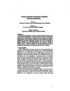
Imagine if, instead, from the first day of class, students are challenged to build a simple but complete system, using most of the concepts they will leam in the class. Piece by piece, they leam about the components they need, design and test them, perhaps good-naturedly competing with their fellow students for the best designs. When they ask if their designs are “good enough,” they are encouraged to check it out for themselves, and to predict how it will affect their system in the end. This system-level design concept is part of a new experimental program at the University of Utah, supported by the National Science Foundation, the College of Engineering, and the University of Utah, to integrate multiple concepts and courses through laboratory design projects. One such project is the design of an FSK communication system for a cardiac pacemaker (Figure l), which combines labs from the junior-level “Signals and Systems” courses and the junior-level electromagnetics course, which are both taught in the same semester. The following is a brief description of the electromagnetics labs.
IEEE Antennas and Propagation Magazine, Vol. 47, No. 2,April 2005
Monopole Antenna wl Match
Transmission Line
Figure 1. A block diagram of the FSK communication system for medical implants.
EM Lab 1: Dielectric Properties In this lab, students learn about the dielectric properties of materials, and how these properties affect electric fields (loss, phase shifl, velocity of propagation, etc.). They make a mixture of water, sugar, and salt that has the same electrical properties as twothirds muscle, and use an HP dielectric-measurement probe to measure its properties. This mixture will be used in the last lab for testing the communication system, and the calculations of loss will be used in the link budget in Lab 7.
EM Lab 2: Transmission Lines In this lab, students leam about different types of transmission lines, including coaxial cable, two-wire lines, and microstrip.
117
They calculate and measure characteristic impedance, and compute and understand R‘ , L’ , G’ , and C’ parameters that are used throughout the class for analysis of transmission lines. They use the measurements of loss on transmission lines in the link budget in Lab 7. A network analyzer and capacitance-measurement system are used.
received from a known transmitter. The reflection and gain from the antenna, the loss in the cables, the loss in the tissue simulation material, and “loss” from the Friis transmission equation are included. The radiation pattern of the antenna is measured, and the effects of multipath are also seen. These effects are included in the link budget, as well.
EM Lab 3: Telegrapher’s Equation Solution using Finite-Difference TimeDomain (FDTD)
EM Lab 8: FSK Communication System
In this lab, students leam how to simulate a transmission line using R’, L‘ , G‘ , and C‘ parameters and Maxwell’s Equations in one dimension with the FDTD programmed in MATLABTM.They simulate how different dielectrics affect the characteristic impedance, loss, and propagation velocity in the line. In future years, we plan to have them also simulate the different layers of a body model, and how the fields will propagate into the torso.
EM Lab 4: Transient Analysis on Transmission Lines and the Time-Domain Reflectometer (TDR) This lab provides additional insight into transmission lines. A time-domain reflectometer is used to determine loads, learn about transient voltages, and better understand the concept of impedance.
EM Lab 5: Monopole Antenna Design and Impedance Matching In this lab, students leam about designing single-stub match-
ing circuits in a steady-state environment. They also learn about antennas, their input impedance, radiation patterns, and how to match the antenna to a source. A monopole antenna with a microstrip feed is tuned to 433 MHz, and matched with a single microstrip (parallel) open-circuited stub. This is made out of copper tape that can be moved around on the board to see the effect of small changes in stub length or location. A network analyzer is used for measurements in this lab.
EM Lab 6: Numerical Integration for Biot-Savart’s Law In this lab, students continue to leam new programming skills to solve the Biot-Savart law, using trapezoidal integration. The magnetic field is computed for the monopole antenna from Lab 5.
EM Lab 7: Link Budget and Radiation Patterns This lab combines many of the previous labs to develop a link budget for a pacemaker communication system. The link budget (programmed in ExcelTM)predicts how much power is 118
This lab is a culmination of many of the other labs to test a simple frequency-shift-keyed (FSK) communication system. This system uses filters that can be designed in the signals course, and the concept of frequency-shifi keying, which uses a frequency of 420 MHz for a “0 or dot” and a frequency of 460 MHz for a “1 or dash.” A message is sent in Morse code from the transmitting monopole antenna from Lab 5 outside the “body” to a folded dipole insulated with silicone inside a vat of the tissue-stimulation material designed in Lab 1. The transmitter is a voltagc-controlled oscillator (VCO), the frequency of which is controlled by a push button and analog circuitry. The receiver is made from two bandpass filters and diode detectors. The link budget from Lab 7 is verified by seeing how far the system transmits. The following is a brief description of the signals and systems labs.
SS Lab I:Fourier Transform and Signal Analysis This lab helps students to understand the concepts of the Fourier transform and signal spectrum through a sequence of fun experiments. It begins with a pre-lab assignment that is done by students before going to the laboratory. In this pre-lab, students’ memory is refreshed on how to use MATLAB as a computational and visualization tool. They also use MATLAB to generate a set of musical notes that they can play and hear. By putting a few notes together, students generate a piece of music. They learn that a signal (such as a piece music) is made up of sine waves. They also experiment and find out how the presence of harmonics can result in more pleasant sounds. This pre-lab is graded and returned to students before they begin their work in the laboratory. The graded pre-labs highlight the students’ weaknesses, and guide them in doing things in a more correct way. During the actual lab session, which runs over two weeks (a total of six hours), students develop a simple MATLAB program for the Fourier analysis of signals. The signals generated in the pre-lab are analyzed using this program. The students are then given another piece of music, which is unknown to them. They use Fourier analysis to analyze this signal, and record the frequency and duration of each note. With this information, they generate the latter piece of music through their own code, and confirm its accuracy by listening to it. At this stage, students have not been taught the Fourier transform in this class, but they have some idea of what the Fourier transform means through their mathematics classes. In our experience, we have found this lab experiment very helphl in preparing students for an in-depth understanding of Fourier-transform concepts and their applications, which are taught in the subsequent weeks in the class. /€€€Antennas and Propagation Magazine, Vol. 47, No. 2, April 2005
I #
SS Lab 2: Modulation Techniques
SS Lab 3: Interpolation
This is a fivc-week-long experiment about frequency and amplitude modulation. Using electronic components, students build a frequency-shift-keyed (FSK) circuit. Both modulator and demodulator modules are constructed and tested. The carrier frequencies used here are 1 kHz and 5 lcHz for representation of logital 0 and 1, respectively. We have purposefully chosen these low frequencies to allow straightforward prototyping in the laboratory using breadboards. The concepts from this experiment are expanded in the EM class, where students build the FSK system in the MHz range.
In the later part of this class, students are exposed to the concept of sampling, Nyquist rate, and the reconstruction of signals from their samples. In this experiment, students learn how digitalfiltering techniques can be used for signal reconstruction. They use MATLAB to design filters for this purpose. This lab is executed over a period of two weeks (a total of six hours).
To further experiment with other types of modulation, the FM signal generated in the first part of this experiment is amplitude modulated (AM)by a 1OOkHz carrier. The corresponding AM demodulator is also constructed, and the complete system consisting of an FM circuit, an AM modulator, an AM demodulator, and an FM detector - is tested at the end of the experiment.
Additional Information Integrated System-Level Design Project:
http://www.ece.utah.edu/-cfurse/NSF Introduction to Electromagnetics: http://www.ece.utah.edu/-ece3300. Contact the authors for the instructor information for this lab. Fundamentals of Signals and Systems: http://www.ece.utah.edu/-ee3500/ @
Coming Soon from Wiley-IEEE Press Differential Forms in Electromagnetics lsmo V. Lindell, Helsinki Universify of Technology This book lowers the step from Gibbsian analysis to differential forms as much as possible by simplifying the notation and adding memory aids. Algebraic tools corresponding to the dyadics of Gibbsian analysis have long been missing from lhe formalism and they are now introduced to differentialforms for the first time. By doing so. the book examines problems of general linear electromagnetic media of engineering interest instead of only simple vacuum problems, which is an area of intense interest for those involved in research on metamaterials. It addresses the mathematical basis of electromagnetism using differentialform formalism to express Maxwell's equations in the simplest possible form.
ISBN: 0-471-64801-9 Price: $99.95 Pages: 256 Date: April 2004
@wr LEY4bIE EE
IEEEAntennas and Propagation Magazine, Vol. 47,No. 2,April 2005
For a complete list of Wiiey-IEEE Press tltles and to order, please visit
www. wi ley.com/ieee
119