Soong and Constantinou, 1994; Skinner et al., 1993). However, consideration of ..... An Introduction to Seismic Isolation, John. Wiley & Sons Ltd, Chichester, ...
Presented at the Second World Conference on Structural Control, Kyoto, Japan, June 28 – July 1, 1998. Proceedings, in press.
Intelligent Base Isolation Systems Erik A. Johnson,1 Juan C. Ramallo,1 Billie F. Spencer, Jr.1 and Michael K. Sain2 1 2
Dept. of Civil Engineering and Geo. Sciences, University of Notre Dame, Notre Dame, IN 46556, USA Dept. of Electrical Engineering, University of Notre Dame, Notre Dame, IN 46556, USA
ABSTRACT An intelligent base-isolation system, comprised of low damping isolation bearings and controllable fluid dampers, is studied in this paper. The damper employs a magnetorheological (MR) fluid that change its properties in the presence of a magnetic field, resulting in a damper whose characteristics may be modified in real time to adapt to changing excitations in a stable and cost-effective manner. A model of a five-story building is used to study and compare the efficacy of a passive base-isolation alone, with the addition of an active control device, and with a semi-active MR damper. A preliminary study of active H2/LQG designs shows that mostly dissipative designs exist, which may be implemented using far less power in an approximate manner with an MR damper. Simulations of the semi-active system demonstrate that the ‘smart’ damper can achieve most of the decrease in base displacement and peak acceleration typical of an active device.
1. INTRODUCTION Base isolation systems are one of the most successful and widely-applied methods of mitigating structural vibration and damage during seismic events. Base isolation systems have been installed in numerous full-scale structures (Kelly, 1981, 1996; Buckle and Mayes, 1990; Soong and Constantinou, 1994; Skinner et al., 1993). However, consideration of near-fault, high-velocity, long-period seismic pulses, as were recorded during the Northridge and Kobe earthquakes, has taught engineers and researchers that ground motion due to such earthquakes can be difficult to accommodate. For example, a base isolated structure in one region of Los Angeles that readily survived the 1994 Northridge earthquake, may well have been destroyed if it were located elsewhere in the region (Makris, 1997). A base isolation system that can adapt to, and protect against, seismic excitation of differing characteristics may help mitigate these problems. Current design codes for seismic isolation (UBC, 1997) have quite conservative requirements, which can lead to large isolators, costly flexible utility connections, and expensive loss of space for the seismic gap. To alleviate these effects, isolators have been augmented with
2
INTELLIGENT BASE ISOLATION SYSTEMS
supplemental damping devices (e.g., Asher et al., 1996); the effect, however, is to decrease base drift at the expense of increasing floor acceleration and structure interstory drifts. Furthermore, when designed for a maximum capable earthquake (MCE), extremely low-probability events, little isolation effect may be realized in more probable moderate earthquakes (Elsesser, 1997). Several active base control systems have been proposed and studied (e.g., Reinhorn et al., 1987; Kelly et al., 1987; Yoshida et al., 1994; Schmitendorf et al., 1994; Yang et al., 1996), with the goal of supplementing passive base-isolation with active control devices to limit base drift. Several small-scale experiments (e.g., Reinhorn and Riley, 1994) have been performed to verify the effectiveness found in the simulation studies. Active control devices, however, have yet to be fully embraced by engineers, in large part due to the challenges of large power supplies (that will not be interrupted during an earthquake), concerns about stability, and so forth. In this paper, a preliminary study of an intelligent base isolation system is presented, using controllable fluid dampers to improve the performance over that of purely passive isolation systems. The proposed system is comprised of low damping isolation bearings and controllable fluid dampers employing magnetorheological (MR) fluid. While controllable isolation systems have been suggested by other authors and shown to be promising, the proposed system employing the MR damper overcomes many of the expenses and technical difficulties of these systems. The focus of this current study is to demonstrate the potential of such ‘smart’ dampers in comparison with active control devices. A model of a five-story building is used as a testbed for this analytical and simulation study. The efficacy of three isolation systems is studied and compared: passive base-isolation alone, augmented by an active control device, and augmented by a semi-active MR damper. It is shown that one may design an active control that is largely dissipative in nature. Using a clipped-optimal form of these control designs and an MR damper performs as well as the active control in constraining base displacements; peak accelerations remain smaller than with the passive isolation system alone, but somewhat increased over the active system in these preliminary results.
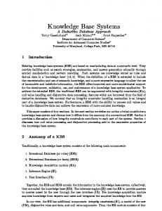
2. PROBLEM FORMULATION 2.1. System Model The structure used in this study is a five-story building model, based on that given by Kelly et al. (1987). The model, shown in both fixed-base and base-isolated configurations in Figure 1, is a lumped-parameter model that assumes the motion of the structure is sufficiently moderate that nonlinearities have minimal effect on the system dynamics. Letting x i denote the displacements of the floor slabs relative to the ground, the equation of motion of the base-isolated system may be written M s ˙x˙ + C s x˙ + K s x = Λ f – M s 1x˙˙g
(1)
where Λ = [ 1 0 ] T gives the position of the MR damper, f is the force exerted by the damper, and 1 is a vector whose elements are all unity. Rewriting in state-space form, with sensors measuring interstory displacements and absolute floor accelerations, gives
JOHNSON, RAMALLO, SPENCER AND SAIN
3
z˙ = Az + Bf + Ex˙˙g
(2)
y = Cz + Df + v where
A=
C=
0 – M s–1 K s
1 , – M s–1 C s
B=
∆ – M s–1 K s
0 , – M s–1 C s
D=
0 M s–1 Λ
,
E=
0 –1
(3)
0 , M s–1 Λ
and ∆ is a matrix giving interbase-isolated fixed-base x5 story displacements (ones on m5 m5 k5 c5 k5 c5 the diagonal and negative ones x4 m4 m4 on the subdiagonal). An addik4 c4 k4 c4 x3 tional filter state is added to m3 m3 k3 c3 k3 c3 model the relatively, but not x2 m2 m2 infinitely, fast dynamics of the k2 c2 k2 c2 x 1 actuator; this also has the benem1 m1 x0 k1 c1 k1 c1 fit of zeroing the D matrix, m0 MR damper which simplifies subsequent x˙˙g k0 c0 control design. The fixed-base structure is chosen to have the same Figure 1. Linear, lumped-parameter model of the structure. parameters and dynamic characteristics as in Kelly et al. (1987), with a fixed-base fundamental period of 0.3 seconds and 2% damping in the first mode. The base mass is chosen to be m 0 = 6800 kg as in Kelley et al. (1987). The base stiffness k 0 is chosen such that the fundamental period of the base-isolated structure is 2.5 seconds. The base isolator is assumed to be low damping isolation bearings such as laminated-rubber bearings, which falls in the ‘Class (ii): lightly damped, linear isolation system’ category of Skinner et al. (1993). It is assumed here that the isolation bearings are indeed linear, with an isolation mode damping ratio of 4%; c 0 is chosen accordingly. The parameters of the structure and passive base isolation are given in Table 1.
2.2. MR Damper Model The MR damper may be modeled using a simple Bingham viscoplastic model (Shames and Cozzarelli, 1992; Spencer et al., 1997), with a viscous damping term in parallel with a controllable yield force f damper = f yield(u) sgn x˙ + c MR x˙
(4)
4
INTELLIGENT BASE ISOLATION SYSTEMS
where c MR is the viscous dampTable 1. Structural model parameters (Kelley et al, 1987). ing coefficient and f yield ≥ 0 is the yield force which is related to Floor Masses Stiffness Damping the fluid yielding stress. The [kg] Coefficients [kN/m] Coefficients [kNs/m] yield force is controllable by m 0 = 6800 k 0 = 231.5 c 0 = 7.45 sending a voltage signal u to the m 1 = 5897 k 1 = 33732 c 1 = 67 electromagnets in the MR device. m = 5897 k = 29093 c 2 = 58 The time constant of a full scale 2 2 device is on the order of 100 ms, m 3 = 5897 k 3 = 28621 c 3 = 57 which is fast in comparison with m 4 = 5897 k 4 = 24954 c 4 = 50 the fundamental natural frequenm 5 = 5897 k 5 = 19059 c 5 = 38 cies of the base-isolated structure. The viscous damping factor and maximum yield force for the MR device are dependent on the size and configuration of the device; for this preliminary study, these properties are assumed max = 12.5 kN . to be c MR = 3000 Ns/m and f yield
3. CONTROL STRATEGIES 3.1. Passive Base Isolation Augmented by an Active Control Device Several studies have focused on the use of active control devices in parallel with a base-isolation system. For example, Kelly et al. (1987) proposed a Lyapunov control design for an active control device installed between the base of a building and the ground. They demonstrated that significant reduction in base displacement could be achieved with this active control. In this preliminary study, an H2/LQG control design is used, assuming in the control design that the ground motion is Gaussian white noise. (A more realistic approach would be to incorporate a shaping filter, such as one corresponding to a Kanai-Tajimi spectrum (Soong and Grigoriu, 1993), into an H2 control design (Spencer et al., 1998; Zhou et al., 1996), so as to more closely match typical earthquake spectra.) The ground excitation and measurement noises are assumed to be independent, and the measurement noises are identically distributed; the ratio of the power spectral density magnitudes is taken to be
γ = S ˙x˙g ˙x˙g ⁄ S vi vi = 49
(5)
The system outputs, absolute accelerations and interstory drifts, are weighted so as to minimize floor accelerations and the base drift. It was observed that decreasing floor accelerations had the side effect of similar decreases in interstory drifts, so the drifts (other than the base) need not be weighted in the control design. In particular, the cost function 1 J = lim --- E τ→∞ τ
τ
1 --- E ∫ ( y T Qy + r f 2 ) dt = τlim τ → ∞ 0
τ
∫ ( { Cz } T Q { Cz } + r f 2 ) dt
(6)
0
is used with a diagonal Q weighting matrix with elements [ q base drift 0 1 × 5 q accels 1 1 × 6 ] and a weight on the force r = 10 –10 (which is small due to the large magnitude of the force
JOHNSON, RAMALLO, SPENCER AND SAIN
5
f relative to the drifts and accelerations in z ). An H2/LQG control may then be designed using one of several convenient tools (e.g., the Control Toolbox in MATLAB®) to solve two Riccati equations. The resulting optimal compensator K(s) is dynamic and of order equal to that of the original plant.
3.2. Passive Base Isolation Augmented by a Semi-Active Control Device In previous studies of MR dampers in seismic protection systems (e.g., Dyke et al., 1996a,b), one control strategy that performed well, a clipped-optimal control, was to assume an ‘ideal’ active control device, use H2/LQG control theory to design an appropriate controller for this active device, and then, using a secondary bang-bang-type controller, try to make the MR damper replicate the same forces the active device would have exerted on the structure. Since the force generated by the MR damper is dependent on the structure and its motion, it is not always possible to produce the ‘desired’ force. In reality, only the voltage to the electromagnets may be commanded. The secondary control law that Dyke et al. (1996a,b) used is given by u = u max H ( f actual [ f desired – f actual ])
(7)
where H (.) is the Heaviside function. Effectively, this law turns the voltage on full when the desired force is dissipative and larger than the measured force. Since the MR damper is an energy dissipation device and cannot add mechanical energy to the structural system, care must be taken in the design of the primary controller (here, the H2/ LQG design) so that the ‘desired’ force is dissipative the majority of the time history of a seismic event. Thus, the first test for the efficacy of an MR damper in such a system for base isolation is to check the rate of energy dissipation, which may be given by rate of energy dissipation = – f actual v
(8)
where v is the velocity across the damper, which, in this case, is the base velocity x˙ 0
4. NUMERICAL RESULTS 4.1. Active Control In order to determine appropriate H2/LQG weighting matrices, an in-depth parameter study was performed. A family of controllers that best decrease base drift or absolute accelerations or some balance of the two were obtained. Three representative controllers were designed with q base drift = 60 and q accels = 20 for the balanced case, and setting one or the other to zero to weight either base drift or acceleration more heavily. Figure 2 shows, for a N-S 1940 El Centro ground excitation, the resulting base drift and the roof acceleration (which was observed to be the peak acceleration for nearly all cases) for the fixed-base, passive, and three actively-controlled cases. The passive system decreases the peak acceleration by 84% over the fixed-base system, but at the cost of 28.3 cm peak base drift. The active control with balanced weights cuts both the peak base drift and peak roof acceleration
6
INTELLIGENT BASE ISOLATION SYSTEMS
fixed base passive active (balanced) active (displ. weight) active (accel. weight)
Base Drift [m]
0.2 0.1 0 −0.1 −0.2
Roof Acceleration [g]
0.2
(peak fixed−base roof accel. is 1.197 g)
0.1
0
−0.1
−0.2 0
5
10
15
20
25
30
35
40
45
50
Time [s] Figure 2. Comparison of base drifts and peak accelerations for the fixed-base structure, the passively-isolated system, and several designs for active base control.
by 57% and 77%, respectively, over the passive system alone. Weighting the accelerations more gives less decrease in peak base drift over the passive case, but with an 81% decrease in peak acceleration. On the other hand, weighting the base drift tends closer to the fixed-base structure, decreasing peak base drift by 79% over the passive case, but with accelerations larger than the passive case. The rate of energy dissipation (rate of work done by the structure on the active control) is shown in Figure 3 for the balanced-weighting case (and the MR controlled case discussed below); the cumulative energy dissipated by the active device is 10.6 kNm, and the cumulative energy added to the structure is 4.9 kNm, for a net energy dissipation of 5.8 kNm. The fact that the active control is energy dissipative for a majority portion of the time record suggests that this system is a good candidate for implementing an MR damper.
4.2. MR Damper in Isolation System The base isolated system augmented by the MR damper was simulated using SIMULINK®. Figure 4 shows a comparison of the base drift and roof accelerations for the fixed-base, passive isolated, active control, and MR damper control systems. The MR damper is able to constrain the base drifts quite well, about 16% smaller than the active case; while it does increase the
7
6000
12000
cumulative (MR) 4000
8000
cumulative (active)
2000 0
4000 0
rate (active) cumulative (active)
−2000
−4000
rate (MR) cumulative (MR) −4000
Cumulative Energy Dissipated [Nm]
Rate of Energy Dissipation [Nm/s]
JOHNSON, RAMALLO, SPENCER AND SAIN
−8000 0
5
10
15
20
25
30
35
40
45
50
Time [s]
Figure 3. Rate of energy dissipation by the MR control device.
fixed base passive active (balanced) MR damper
Base Drift [m]
0.2 0.1 0 −0.1 −0.2
(peak fixed−base roof accel. is 1.197 g)
Roof Acceleration [g]
0.15 0.1 0.05 0 −0.05 −0.1 −0.15 0
5
10
15
20
25
30
35
40
45
50
Time [s] Figure 4. Comparison of base drifts and peak accelerations controlled with an MR damper.
peak acceleration somewhat over that of the active control case, it is still 41% below the peak accelerations of the passive isolation system alone. Table 2 lists the peak responses for each of the control strategies for several earthquake excitations. The MR damper isolation system does not perform quite as well for the near-field earthquakes studied herein, as may also be seen in Figure 5, which gives the base drifts and roof
8
INTELLIGENT BASE ISOLATION SYSTEMS Table 2. Maximum base drift, absolute accelerations, and applied force. Ground Motion
El Centro
Hachinohe
Kobe
Northridge
El Centro*
Peak Base Drift [m] Passive Isolation
0.283
0.426
0.366
0.822
0.344
Active Control
0.123
0.146
0.183
0.365
0.127
MR damper
0.103
0.096
0.282
0.534
0.115
Peak Absolute Acceleration [g] Fixed base
1.197
1.054
2.954
4.005
1.197
Passive Isolation
0.190
0.282
0.247
0.544
0.227
Active Control
0.043
0.043
0.107
0.161
0.040
MR damper
0.112
0.101
0.205
0.382
0.123
Active Control
25269
29969
37353
74023
26099
MR damper
12819
12555
14071
15561
13022
Peak Applied Force [N]
* using 0.56% isolation-mode damping as per Kelly et al. (1987) instead of the 4% used elsewhere herein
0.2
Base Drift [m]
0.1 0 −0.1 fixed base passive active (balanced) MR damper
−0.2 −0.3
(peak fixed−base roof accel. is 2.9537 g)
Roof Acceleration [g]
0.2
0.1
0
−0.1
−0.2
0
5
10
15
20
25
30
35
Time [s] Figure 5. Comparison of base drifts and peak accelerations for the MR controlled system under a Kobe excitation.
40
45
9
30 25
cumulative (MR)
25
20
cumulative (active)
20 rate (active) cumulative (active)
15 10
rate (MR) cumulative (MR)
5
15 10 5
0
0
−5
−5 0
5
10
15
20
25
30
35
40
Cumulative Energy Dissipated [kNm]
Rate of Energy Dissipation [kNm/s]
JOHNSON, RAMALLO, SPENCER AND SAIN
−10 45
Time [s]
Figure 6. Rate of energy dissipation by the MR control device with a Kobe excitation.
accelerations due to 1995 N-S Kobe ground excitation. Here, the base drift and peak acceleration of the MR system are smaller than the passive system but only about 20% less, in contrast with the active control at 50-60% less than the passive results. Part of the reason for this decreased efficacy is undoubtedly that the control parameters were tuned to perform well during an El Centro excitation. Additionally, the energy dissipation by the MR device, which was double that of the active control for the El Centro earthquake, is not much more than the active control in the Kobe earthquake (see Figure 6).
5. CONCLUSIONS A comparison study covering two possible types of ‘intelligent’ base isolation systems, ideal fully active and semi-active via MR damper, was performed. The response to several earthquake excitations were computed. This preliminary study suggests that MR dampers show significant promise in base isolation applications with greatly reduced power requirements. Several important items remain for future study. First, although the control strategy used herein has been shown to be effective, there are a number of other viable contenders (Dyke and Spencer, 1997) that should be considered. Second, as base isolation systems are designed based on the so-called Maximum Capable Earthquake (MCE), the control algorithms used herein should be tuned to the strong, near-field earthquakes (e.g., Kobe and Northridge) and, then, their performance under more moderate earthquakes (e.g., El Centro and Hachinohe) gauged.
ACKNOWLEDGMENTS The authors gratefully acknowledge the partial support of this research by the National Science Foundation under grants CMS 95-00301 and CMS 95-28083 (Dr. S.C. Liu, Program Director) and by a fellowship from Consejo Nacional de Investigaciones Cientificas y Tecnicas (Republica Argentina).
10
INTELLIGENT BASE ISOLATION SYSTEMS
REFERENCES Asher J.W., Young R.P., and Ewing R.D. (1996). Seismic Isolation Design of the San Bernardino County Medical Center Replacement Project. J. of Struct. Des. of Tall Bldgs., 5: 265-279. Buckle I.G. and Mayes, R.L. (1990). Seismic Isolation History, Application and Performance — A World View. Earthquake Spectra, 6: 161-201. Dyke S.J. and Spencer B.F. Jr. (1997). A Comparison of Semi-Active Control Strategies for the MR Damper. Intelligent Information Systems Conference (IIS’97), Grand Bahama Island, Bahamas, December 8-10, 1997. Proceedings, 580-584. Dyke S.J., Spencer B.F. Jr., Sain M.K. and Carlson J.D. (1996a). Seismic Response Reduction Using Magnetorheological Dampers. Proc. IFAC World Congress, San Francisco, CA, June 30 July 5, L: 145-150. Dyke S.J., Spencer B.F. Jr., Sain M.K. and Carlson J.D. (1996b). Modeling and Control of Magnetorheological Dampers for Seismic Response Reduction. Smart Materials and Structures, 5: 565-575. Elsesser E. (1997). Forell/Elsesser Engineers, Inc., Private communication. International Conference of Building Officials (1997), Uniform Building Code, Earthquake Regulations for Seismic Isolated Structures, Appendix Chapter 16, Whittier, CA. Kelly J.M. (1981). Aseismic Base Isolation: Its History and Prospects. Proc. 1st World Congress on Joints and Bearings, ACI-SP-70, 1: 549-586. Kelly J.M. (1996). Earthquake Resistant Design with Rubber, 2nd edition, Springer-Verlag, London. Kelly J.M., Leitmann G. and Soldatos A.G. (1987). Robust Contorl of Base-Isolated Structures under Earthquake Excitation. J. of Optimization Theory and Applications, 53: 159-180. Makris N. (1997). Rigidity-Plasticity-Viscosity: Can Electrorheological Dampers Protect Base-Isolated Structures from Near-Source Earthquakes. Earthquake Engrg. and Struct. Dyn., 26: 571-591. Reinhorn A.M. and Riley M. (1994). Control of Bridge Vibrations with Hybrid Devices. Proc. 1st World Conf. on Struct. Control, Los Angeles, CA, TA2: 50-59. Reinhorn A.M., Soong T.T. and Wen C.Y. (1987). Base-Isolated Structures with Active Control. Proc. ASME PVP Conf., San Diego, CA, PVP-127: 413-420. Schmitendorf W.E., Jabbari F. and Yang J.N. (1994). Robust Control Techniques for Buildings Under Earthquake Excitation. Earthquake Engineering and Structural Dynamics, 23: 539-552. Shames I.H. and Cozzarelli F.A. (1992). Elastic and Inelastic Stress Analysis, Prentice-Hall, Inc., Englewood Cliffs, N.J. Skinner R.I., Robinson W.H. and McVerry G.H. (1993). An Introduction to Seismic Isolation, John Wiley & Sons Ltd, Chichester, England. Soong T.T. and Constantinou M.C. (Eds.) (1994). Passive and Active Structural Vibration Control in Civil Engineering. Springer-Verlag, Wien and New York. Soong T.T. and Grigoriu M. (1993). Random Vibration of Mechanical and Structural Systems. Prentice Hall, Englewood Cliffs, New Jersey. Spencer Jr., B.F., Dyke, S.J. and Deoskar, H.S. (1998). “Benchmark Problems in Structural Control – Part I: Active Mass Driver System and Part II: Active Tendon System.” Earthquake Engrg. and Struct. Dyn., to appear. See also www.nd.edu/~quake/benchmarks/. Spencer B.F. Jr., Dyke S.J., Sain M.K. and Carlson J.D. (1997). Phenomenological Model of a Magnetorheological Damper. Journal of Engineering Mechanics, ASCE, 123: 230-238. Yang J.N., Wu J.C., Reinhorn A.M and Riley M. (1996). Control of Sliding-Isolated Buildings Using Sliding-Mode Control. Journal of Structural Engineering, ASCE, 122: 179-186. Yoshida K. Kang S. and Kim T. (1994). LQG Control and H∞ Control of Vibration Isolation for MultiDegree-of-Freedom Systems. Proc. 1st World Conf. on Struct. Control, Los Angeles, CA, TP4: 43-52. Zhou K., Doyle J.C. and Glover K. (1996). Robust and Optimal Control. Prentice Hall, Upper Saddle River, New Jersey.