Intelligent Counter System for Generating Attendance N. Edna Elizabeth, T. K. Gowthaman, J. Joannes Sam Mertens and P. Likhitta Dugar
Abstract In the present time, in most educational institutes, proxy is witnessed as one of the most inexcusable violences of the rules and regulations. It is also often observed that the attendance in all the educational institutes is taken manually by the faculty in charge to avoid proxy, but ends up in reducing the productive time available in the classroom. The solution to the above-faced difficulties is to bring about an automated system to mark the student’s presence in each hour. Thus, the aim of this project is to bring a two-factor authentication system for generating the attendance by integrating the radio frequency identity cards along with biometrics. The result shows the prototype of the system designed with security. Also, wireless communication through radio waves between the transmitter and the receiver is carried out in this work. Keywords Two-factor authentication Automated system
⋅
Biometrics
⋅
Proxy avoidance
N. Edna Elizabeth ⋅ J. Joannes Sam Mertens Electronics and Communication Department, Sri Sivasubramaniya Nadar College of Engineering, Old Mahabalipuram Road, Kalavakkam 603110, Tamil Nadu, India e-mail:
[email protected] J. Joannes Sam Mertens e-mail:
[email protected] T. K. Gowthaman ⋅ P. Likhitta Dugar (✉) Sri Sivasubramaniya Nadar College of Engineering, Old Mahabalipuram Road, Kalavakkam 603110, Tamil Nadu, India e-mail:
[email protected] T. K. Gowthaman e-mail:
[email protected] © Springer Nature Singapore Pte Ltd. 2018 J. Anguera et al. (eds.), Microelectronics, Electromagnetics and Telecommunications, Lecture Notes in Electrical Engineering 471, https://doi.org/10.1007/978-981-10-7329-8_2
11
12
N. Edna Elizabeth et al.
1 Introduction The current scheme used for marking the attendance in the classroom is very time consuming and not entirely secure in terms of avoiding proxy. Hence, the idea to develop a handy terminal was implemented. The incapability of manipulating the biometric human characteristics was a major concern while implementing the project. It is used by assigning the fingerprint to their individual details, like name and unique register number in their passive Radio Frequency Identification (RFID) tags. The successful matching of both the authenticated factors helps in enlisting and creating a database for each time the attendance is generated. This system is carried out by the integration of a fingerprint scanner along with an RFID reader and a Liquid Crystal Diode (LCD) screen. The LCD screen is used to display the acknowledgment and to avoid any mismatch of data. With the help of an Arduino UNO 3 using the transceiver, Serial Peripheral Interface (SPI) communication is the methodology used to communicate with the student terminal to the faculty terminal and vice versa. The faculty terminal is a complete integration of the transceiver with the database storage device as an individual module. As a device for local storage, a computer/laptop present in each classroom is used. The present local storage device is only accessible by the faculty in charge, of that particular hour. On the confirmation of the database observed on the Graphical User Interface (GUI), it is transferred to the faculty’s Simple Storage Device (SSD) for anytime access. Our major concern is to access any particular hour’s attendance by the faculty, within the premises, in case of any discrepancies. The faculty is the sole controller. There are already available attendances marking systems but lack in some way or the other when taken into account the proxy or possible violations. The readily available systems are either wall mount or designed on only one-factor authentication. When taken in the case of the wall mount biometric systems, there is a possibility of intentional time waste in doing the same. On the other hand, while analyzing the case of the available one-factor authentication system, i.e., RFID or biometric factor, there is no evidence of proxy or other malpractices. In present time, at the end of each attendance slot allotted by the universities, it becomes a tedious job for faculties to create the database and get it reviewed by each and every student to avoid discrepancies, which lead us in creating this automated counter system.
2 Related Works The article [1] has proposed a design using the emerging technology for identification (not proper format). Biometric refers to automatic identification of a person based on biological characters such as fingerprint, iris, facial recognition, etc. In this
Intelligent Counter System for Generating Attendance
13
article, the main heart of the circuit is fingerprint module. This sends commands to the controller whenever fingerprint is matched. Anif Jamaluddin et al. [2] have proposed a design for the improvement of assessment model using RFID technology which is implemented on Computer Based Test (CBT). But this system still needs human as a proctor for monitoring server. G. V. Ambadkar and A. R. Karwankar [3] described the implementation techniques of RFID, integrated with biometric sensor to improve the security system. In this system, it uses both the techniques for registering proper attendance of student. No one can give proxy. It operates when the students swipe their RFID tag and also access the biometric, so that the attendance gets marked and the class door gets opened for the day. The limitation in the above paper is that the attendance was marked only at one instance in the whole day. This leads to high percentage of the students’ attendance, for every subject even if the particular student was absent on particular class hours on several days. Kong Shengli et al. [4] have explained the basic concept of the connection of RC522 reader to the Arduino platform for the acquisition of RFID card information. They have also given the optimum frequency of working as 13.5 MHz. They state that the usage of RC522 reader is for low power consumption, low cost, and low voltage requirements.
3 Proposed System Overview 3.1
Introduction
The system consists of a transmitter module and a receiver module. The microcontroller is common to all modules and it performs logical operations. The transmitter is placed on the students’ desk, while the receiver is connected to the faculty accessible laptops. For communication between the transmitter and receiver, Serial Peripheral Communication (SPI) is used. This can be adapted easily by the windows operating software which is analyzed to be a common platform of operation in the present times. SPI communication was chosen as there are a common clock and other general signals. This type of communication is preferred as they communicate from one to many devices by just proving single and separate “chip enable” pin layouts for each device that is being connected and used.
14
3.2
N. Edna Elizabeth et al.
Transmitter
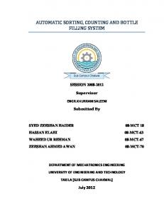
The transmitter module consists of the Arduino UNO 3, fingerprint sensor module, the RFID reader, a 16 × 2 LCD screen, and the nRF24L01 transceiver. A communication link is established between the transmitter and the receiver, when the transmitter module receives the initializing signal transmitted from the module present in the faculty side. Figure 1 describes the transmission module which contains the fingerprint sensor, Arduino, RFID reader, LCD, and transceiver. Once the initial signal is received, the Arduino supplies power to the LCD screen and the RFID reader. The LCD screen first displays, stating that the module is ready to accept and receive data. The students are asked to swipe the passive tags that are distributed individually consisting of unique RFID numbers. Initially, a database is created in the faculty accessible laptop, when the students are simultaneously made to enroll one of their fingers as password along with the tag swipe, for the two factors of authentication. In the case of mismatching of the fingerprint and the RFID retrieved details, the error messages are displayed on the LCD screen. This ensures a high-level security in the attendance system.
3.3
Receiver
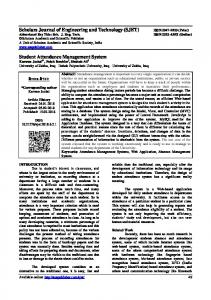
The message signals from the various transmitters present are received by the module that is present at the receiver end. This module is an integrated system of the Arduino UNO 3 with the transceiver. Figure 2 describes the receiver module which contains an Arduino and a transceiver. This module is also used as the initialization system. When this receiver
Fig. 1 Transmission module
Intelligent Counter System for Generating Attendance
15
Fig. 2 Receiver module
module is powered on by the faculty, through the method of SPI communication, it is observed that the receiver module sends the initial enabling signals to all the connected modules (transmitter) present in that classroom. The signal is sent to each module and there is a particular time slot given to the students by the faculty within which they are asked to post in their attendance by passing through the two-factor authentication procedure. At the end of that time slot, the receiver module resends a signal which collects the generated list of attendance. On the successful reception of the data, the receiver sends the acknowledgement signal back to the students’ module, stating the confirmation of the attendance received. On the contrary if there is any loss of data or errors observed, that particular unique ID number would not get an acknowledgement, by which they are required to repost their attendance.
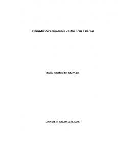
4 Proposed System Execution Implementing the process flow of the system is the major part that should be done carefully. Interfacing each component individually with Arduino UNO 3, and then integrating them completely, gives the final counter system. The student’s terminal is the first step, which consists of an RFID reader and the fingerprint sensor with an LCD display connected to the Arduino UNO along with a transceiver. Next is the faculty terminal, which has an Arduino UNO 3 connected with a transceiver which receives the data sent from the students terminal and displays it on the laptop screen which the faculty accesses. The transceiver present at both the terminals is used for sending and receiving data. Further, there is a discussion about the interfacing steps for each component in the system. In Fig. 3, the overall system process flow is shown. As seen in the process flow diagram, the proceedings of this counter system begin when the students’ side terminal get powered on by the initializing signal received from the teacher’s terminal. Once the student terminal is powered, the students are accessible to scan their tags along with matching their respective enrolled finger for marking their attendance. On the event of both the factors of authentication, a temporary database is created and stored in the Arduino present in the student terminal. Once the faculty
16
N. Edna Elizabeth et al.
Fig. 3 Attendance process flow
in charge clicks on the “STOP” button, there is a link created between the transceivers of the faculty and student terminals. Through SPI communication by the link, the temporary stored database is communicated and enlisted on the GUI screen on the faculty side terminal. The enlisted database created is then saved and used for further processing by the faculty.
4.1
Interfacing RFID with Arduino
This stage is the first factor for authentication, which is done using the RFID tag and reader. The passive RFID tag is made to swipe over the reader which uses its signals to capture the data from the tag swiped. The reader sends energy to an antenna which converts it into an RF wave and sends it into the read zone. Once the tag is read within the read zone, the RFID tag’s internal antenna draws in energy from the RF waves. Mifare RFID reader is connected to the Arduino UNO R3 with its respective pin configurations. The LCD-connected pins, i.e., the secret slave pin and the reset pin of the RFID, are defined. Each card is read by the reader and the unique ID associated with each card is defined with its owner. The details of this owner (i.e., the name of the owner) of that particular card are made to display on the LCD screen as well as the serial monitor screen. When the faculty in the class is ready to take attendance, the faulty gives in the power signal from the terminal present there and once each unit receives the initial start signal, the LCD monitor
Intelligent Counter System for Generating Attendance
17
Fig. 4 Interfacing RFID with Arduino
present in the students terminal displays the message that reads “SCAN CARD WHEN INSTRUCTED” as shown in Fig. 4. Once the student swipes his RFID tag on the reader, the LCD displays the student’s name (owner’s name). In case of any unauthenticated card tapped on the reader, it will display an error message stating the detection of an invalid card.
4.2
Interfacing Biometric with Arduino
The second factor of authentication is carried out by using the biometric factor, i.e., the fingerprint sensor as shown in Fig. 5. Fingerprint authentication refers to the automated method of verifying a match between the saved fingerprint image and the fingerprint scanned at that moment. Fingerprint is one of many forms of biometrics which is said to be unique and is used to rightly identify individuals or verify their identity, addressed by the enrolment and matching of the fingerprint. The module is connected to Arduino UNO 3 and LCD with its respective pin configurations. ENROLING—Here, the student’s finger is placed twice for confirmation while creating the image and is then made to recognize by the Arduino. By the captured images, a database is created by the allocation of unique ID numbers (starting from 0).
18
N. Edna Elizabeth et al.
Fig. 5 Interfacing biometric with Arduino
MATCHING—The initial setup is kept the same as that in the enrolling step. The fingerprint sensor is programmed to blink until it identifies and captures a valid finger. Upon capturing, it is compared with the already existing images in the database. If a matched fingerprint is found, the associated ID is displayed on the LCD display. Depending on the instructions displayed on the LCD, the student imprints and acquires the confirmation with the associated unique number. On the contrary, if it does not match, it displays the error message “NOT MATCHED”.
4.3
Integrating RFID and Biometric
This step deals with the integration of the above two explained stages. Each RFID unique number is tagged not only with the owner’s name but also with their respective biometric information. At first, the RFID is made to tap on the reader and once the first factor is authenticated successfully, it is then lead to the second level of authentication. At this stage, it captures the fingerprint and checks if it matches with the details pertaining to that of the unique ID of the matched RFID tag. In Fig. 6, once the student “X” swipes the RFID tag and gets successfully recognized by the reader, the LCD displays as follows:
Intelligent Counter System for Generating Attendance Fig. 6 Integrating RFID and biometric
19
X PLACE YOUR FINGER
The student X then will place the enrolled finger on the fingerprint sensor, assuming it was enrolled with the number “1” and gets it verified as the second factor of authentication. If both, the RFID and fingerprint, match successfully, the LCD displays and the next continues the same process to mark his attendance. This is shown in Fig. 7.
Fig. 7 Integrating RFID and biometric
1 OK MATCHED
20
4.4
N. Edna Elizabeth et al.
Transmission of Data
The nRF24L01 transceiver is connected on both ends to send and receive the student’s data in each hour. The transmission/reception of data through the transceivers takes place only when the numbers of both the transceivers trying to connect and communicate are verified to be the same. In the case of identification of different numbers, there is no communication that takes place between those two transceivers.
4.5
Display of the Database
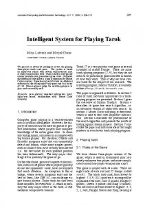
The final step of this counter system is the display of the database on the faculty accessible laptop screen. The data received through the transceiver is displayed on the GUI created for each laptop. The application (or) GUI created on the laptop is programmed such that the faculty has the control from the beginning to the end of attendance process. Once all the databases from each unit in the class are collected,
Fig. 8 Form of the students present
Intelligent Counter System for Generating Attendance
21
the GUI gives the list of all the students who have marked their attendance in the classroom during that particular hour. Figure 8 shows the created GUI which has a presentation screen on which the dates with the respective period numbers are mentioned. On the event of clicking upon a particular period, a list of the created database appears on a side tab. The form is used for creating and storing the initial database of all the students in the educational institution. The form is filled when the students are enrolled in the educational institution at the time of admission. Alongside is also given a provision of viewing the personal information, such as their name, photo, register number, etc., upon selecting the student’s database created.
5 Conclusion and Future Work Thus, the attendance database generated by the intelligent counter system, through the two-factor authentication, is a secured system and does not involve any manipulation of data. Despite the existence of various methods which propose the generation of attendance using RFID solely or the generation of attendance by using only the biometrics factor, our proposed work stands high with the combination of both RFID system and the biometric for a secured way of authenticated attendance marking, thus avoiding proxy. The most common and efficient way of communication is purely wireless. So wireless communication through radio waves is what is carried out in this work. Interference or loss during the transmission is very less compared to the usual communication as SPI communication is the methodology used in this project. For reducing the burden of the faculty and by eliminating the large amount of time taken during marking the attendance, this intelligent counter system does justice. Another aspect of work that can be done using the RFID tag is by replacing it with a smart card [5]. Each student having their own smart card can access it for multiple purposes in the college premises, for example, paying their fee, using it for paying bills in cafeteria, Xerox purposes, and also for transit application [5].
References 1. “Biometric Attendance System Circuit” http://www.electronicshub.org/biometric-attendancesystem-circuit/ (22 October 2015) 2. Anif Jamaluddin; Dewanto Harjunowibowo; M Akbar Rochim; Fajar Mahadmadi; HBulan Kakanita; Pringgo W. Laksono “Implementation of RFID on Computer Based Test (RF-CBT) system”, Proceedings of the Joint International Conference on Electric Vehicular Technology and Industrial, Mechanical, Electrical and chemical Engineering (ICEVT & IMECE), pp. 153– 156, https://doi.org/10.1109/ICEVTIMECE.2015.7496645, IEEE Conference Publications (2015)
22
N. Edna Elizabeth et al.
3. G.V. Ambadkar, A.R. Karwankar, “RFID and Fingerprint Based Student Attendance System”, International Journal of Industrial Electronics and Electrical Engineering, ISSN: 2347-6982, vol 3, (4 April 2015) 4. Kong Shengli, Zhao Jun, Shi Guang, Wu Chunhong, Zhao Wenpei, “The Design and Implementation of the Attendance Management System based on Radio Frequency Identification Technology”, International Conference on Electronic Science and Automation Control, (ESAC 2015) 5. Edna Elizabeth. N, Nivetha S, “Design of a Two-factor Authentication ticketing system for Transit Applications” IEEE TENCON 2016-Technologies for Smart Nation, 22–25 November 2016, Marina Bay Sands, Singapore, pp 2498–2504 (IEEE Xplorer) https://doi.org/10.1109/ TENCON.2016.7848483