Intelligent Energy Monitoring System Based on ZigBee-Equipped Smart Sockets Mon-Chau Shie, Po-Chen Lin, Tsung-Mao Su, Poki Chen and Antony Hutahaean Department of Electronic and Computer Engineering, National Taiwan University of Science and Technology, Taiwan, R.O.C. Email:
[email protected],
[email protected],
[email protected],
[email protected],
[email protected]
Abstract—The intelligent home appliance monitoring is the mainstream development of the future automation and networking technology. Appliance operation can be easily monitored through sensing and other similar perceptions of the corresponding power link. These products of smart energy monitoring system communicate with one another via intelligent sockets equipped with ZigBee wireless transceivers. A homebased remote server enables remote monitoring and control of electrical home appliances. The use of mobile internet in portable devices, especially in smartphones and tablet PCs, provides great advantage and flexibility for remote control. The status and power consumption information of all monitored appliances are stored in the remote server. The corresponding analysis of such power consumption data can be provided to the power company for smart grid planning and the user for energy saving through rescheduling and safe power usage via abnormal situation warning. Index Terms - Smart Socket, ZigBee, MCU, Smart Energy Monitor, Intelligent Control
I.
INTRODUCTION
This paper proposes an intelligent system that provides users with fruitful functions for the monitoring and remote control of home appliances. The use of mobile devices has even extended the range of possibilities of smart control since the operations may be implemented on the mobile devices to make the intelligent control more accessible and flexible. The use of mobile devices is not only for sensing electrical device status but also for monitoring power consumption and receiving warnings of improper use of electrical energy. In the future, every single electrically powered device at home will be possible to be “seen” by user’s mobile devices and ready to be controlled and thoroughly monitored. All of the abovementioned thoughts will be realizable with an extensive use of intelligent socket systems integrating automatic power measurement modules and wireless network controller. It is similar to home automation with remote control of all accessed nodes. All the nodes connected to home loads act as relay stations. The information exchange regarding power consumption will be uploaded to a remote database and web servers, and thus an analysis of electricity usage data will be provided. In the web, user will be supplied with a remote control interface for a graphic monitoring and energy state management. Due to the large amount of consumption data,
measurements are to be made according to the available information and analysis of consumed electricity. Implementation of the intelligent energy monitoring system will achieve a safe use of household appliances and reach the target of energy-saving by remotely controlling the operation state of devices. It can also reduce the cost for total energy consumption through effective management and consumption time re-distribution. It’s an urgent mission to reduce carbon emission by saving energy consumption for all countries on earth. Since Taiwan is a small country with a relatively high population density, energy consumption efficiency becomes a more significant issue than in other countries. In terms of electrical energy demand, a random family unit can effectively save energy by using the energy monitoring system. For example, proper planning of electricity consumption for each household level will likely avoid a massive energy wastage. It will surely help to achieve a sustainable development of Taiwan's energy sector. More importantly, the proposed system has a security warning mechanism. People spend most of their time at home and therefore to provide a safe and secure home environment for humankinds is a really a matter of concern. The use of more home appliances means not only more convenience but also more risk caused by improper use or malfunction of appliances which may potentially result in fire later on. A complete monitoring system, which includes real-time monitoring, remote control and abnormal warning notifications to control home appliances, is surely required. To solve all the problems mentioned above, the proposed intelligent power monitoring system focuses mainly on energy-saving and disaster prevention. Accordingly, timing devices are intelligently used for appliance scheduling to make life much more convenient and substantially reduce the electricity cost. Also, real-time monitoring is adopted to improve home security. In the future, the proposed system can integrate more existing technologies, such as home security system, monitors, fire alarms, smoke detectors, and automatic sprinkler system, to provide users more security and functionality. The establishment of a truly intelligent energy consuming environment starts from private apartments or houses and then expands all over the communities, cites or even to larger areas, if negotiation among regional power companies can be made. It will provide smart electricity
man nagement, enhhance the levvel of powerr monitoring and effecctively controol the energgy supply an nd use to reeduce unneecessary loss and form a complete “p power monitooring umb brella”. II.
CONCEPT OF INTELLIGENT SYSTEM
A. Internet I of Thiings Nowadays, N thhe term “interrnet of things” begins to gain moree and more cooncerns for thhe world surro ounded by var arious electtronic devicess. Without theem, our lives would w become me not so comfortable c annd relaxed. Most M current electronic devvices equipped with prrocessors or microcontrolle m ers are able tto be conn nected with thhe “outer woorld”. In other words, theyy are coup pled by meanss of internet. These T numerous devices conntain speccific functionss that they weere made for,, such as wasshing mach hine for cleanning clothes and a kitchen oven o for prepaaring food d … etc. Thesse exemplary appliances a aree brought to ““life” in th he way how we have gott used to them m through sim mple man nual adjustmennt. Much morre convenience can be expeected if these t devicess can be operated o witthout any ddirect anth hropogenic innterference. At A current staage, the term m of “inteernet of thinggs” seems to be a good so olution. Theree are vario ous kinds of ssystems that implement i thee idea of “intternet of things”, t but all of them have thee same targget interrconnection of various devvices and effeective control over them m.
statiistics to get riid of the neceessity of apply ying manpoweer for read ding power meetering data eeach month. The T reading errror is also o eliminated au utomatically. Implementatio I on of this conncept is similaar to that of home h auto omation with remote contrrol of the nod des. The propposed intellligent sockeet system inntegrates pow wer measureement mod dules with wireless w netw work controll. All the nodes n conn nected to the home loads act as relay stations also.. The info ormation exchaange regardinng power savin ng is uploadedd to a remote database and web servvers. Thus, an analysis off user mption can be provided. elecctricity consum
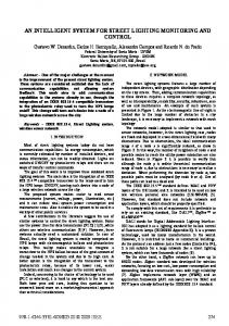
Fig.2. Architectu ure of the proposeed smart energy monitoring m system m
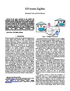
Fig.1. Functtional block diagrram of the GSM Power P Meter
In I terms of web, a remo mote control interface i musst be pressented under user’s queryy. Due to thee large amounnt of conssumption dataa, measuremeents are to bee made only when w neceessary. Also reducing the fr frequency of measurement m m might play y a big role in n striving to thhe goal of eneergy-saving. Fig. F 2 illusstrates the enttire structure of the proposed system whose w smaart socket usess FET (field-efffect transisto or) as power sw witch and ZigBee module for wirreless commu unication. ZiigBee dule transmits the electricitty usage data including volltage, mod currrent, power, energy e and poower factor (P PF) to monitoor the elecctricity load att home. Userss may connecct through Intternet to a remote serveer that monitoors all active devices to geet the pow wer consumption curves of tthe interested nodes.
B. Power P Measurring Modules As A technologyy evolved, soocket and meter so far aree not simp ple links betw ween power annd device onlly. A combinnation of ellectronic com mponents allow ws users to haave better life than befo ore. For exampple [1], an inffrared remote controller is used to sw witch socket aand set scheddule. It can no ot only be useed in hom me environmennt but also bee applied to industrial i opeerator that cannot be poositioned too close to the outlet o due to high perature or higgh-pressure. The T effective operating disttance temp is approximately a y 8 meters which w makes it applicablle to vario ous environm mental condittions. Smart meters also take advaantage of GS SM module which impleements the A AMR techn nology (Autoomatic meterr Reading) [2 2]. The statuus of electtricity user iss transferred by b means of SMS messag es to pow wer companies as shown in Fig. F 1. The po ower companiees, in turn,, can automaatically updatte the user's electricity uusage
C. Smart Grid and Intelligentt Socket System ms Any A househo old appliancess needs to be b connected to a sock ket. A socket represents a ccertain node “reachable” “ in each family and invokees the idea off smart home-aautomation syystem nt of a large--scale creaation. It also promotes thee establishmen smaart grid with h the integgration of power p generaation, transmission and distribution to form a com mplete energy cycle o the [3]. The idea off a smart gridd is differentt from that of way power neetwork. Userss are now abble to traditional one-w nd bi-directioonally acceess complete electricity innformation an exch hange it with power comppanies. One major m differennce of smaart grid from the t existing ppower supply system will be in alloccating and ad djusting differrent periods of o electricity usage u to acchieve energy y-saving [4]. The T concept of o a smart gridd is founded on o the idea thhat by sharring information concerningg allocation of o the most opptimal
pow wer resources, electrical devvices are pow wered throughh the help of some speecial-purpose sensors. A deense and com mplete y reduces the ccosts, electtrical networkk is thus formeed. It not only enhaances reliabiliity but also improves effi ficiency of ennergy usag ge. In the futuure, the convventional pow wer system wiill be com mpletely replacced with the smart grid. It I will result in a chan nge of the eelectricity bill that will carry c much m more detaiiled consumpption informaation. The fig gures of dailly or mon nthly energy consumption will no longer be displaayed. Insteead, the montthly power coonsumption will w be represeented as a "power curvve" which grraphically deescribes electrricity conssumption in a great detaill. It will even n enable user ers to peneetrate into the hourly analyysis of power estimation. P ower com mpanies will also acquire new w "time tarifff "charges. In oother word ds, the use off electricity duuring the day y will be splitt into perio ods of peak hhours with higgher rates and d off-peak per eriods with h correspondinngly lower onnes. The user will be motivvated to taake advantage of the off-peak energy perriods and conssume the high-price h tariiffed electricaal energy of peeak hours onlly for high hly needed elecctronic devicees.
ocket to the home h conssumption dataa wirelessly ffrom smart so load d monitor and even further to mobile po ortable devicess. All smaart sockets in nstalled withiin one living g space unit (i.e. priv vate house, flaat in apartmen ent house, or cottage) are quasi merged by one single supervvising ZigBeee coordinator.. The ormation of all a smart sockkets installed d within the same info livin ng space unitt will be colllected through h ZigBee prootocol and synchronouslly pushed to tthe home serv ver, also know wn as me load monittor. The wholle cycle of po ower consum mption hom info ormation co ollection inncludes two o more steps: s com mmunicating with w an exterrnal database (in our casee, the serv ver is installed d in our researrch laboratory y) and bidirecttional conn nection of mo obile device, ssuch as smartp phone or tableet PC with h the databasse. The inforrmation aboutt electrical power p conssumption is pu ushed throughh different staages to finallyy land in user’s u smart device. Thee last stage equips user with mon nitoring and controlling funnctions. In oth her words, useer has the capability c of turning t on/offf any of the electrical devicces at hom me when necesssary, setting operation perriods for them m and distaantly tracking the actual eneergy consump ption level.
D. Prerequisities P of a Smart Syystem Implemeentation Facing F harsh competition and environ nmental prote ction issuees, effective electric pow wer managem ment is acti tively prom moted. Improvving power suupply efficien ncy has becom me a goal of many counntries to vigorrously supporrt and facilitatte the integ gration of disstributed geneeration, smartt grid and ennergy inforrmation appliications. Smaart grid consstruction and ICT (Info ormation Com mmunication Technology)) applicationn are utilizzed together to provide automatic control c (e.g. selfhealiing), demaand responsse management, real--time measurement (insstant informaation), and th he optimal p ower m will contribute a llot to conffiguration function. Such measures the power sectoor as well as a to supply y integration and maanagement. For pow wer compaanies, scheeduling impllementation oof intelligentt power supp ply and effeective transsmission systeems will be of a great beneefit of being aaware of prrecise power usage and haaving a clear grasp g of the uuser’s enerrgy demands in order to allocate electtricity effectiively. With h the implemeentation of sm mart grid and specific timee unit tarifff, user can m manage electrrical load wh hen the electrricity peak k and off-peakk becomes obvious. Since the t electricityy cost is ex xpected to riise in near future, f these measures willl be extreemely useful. Moreover, onne of the main n advantages oof the smarrt grid implem mentation is to t conduct an n effective rem mote operration of homee appliances [55].
B. General G Systeem Architecturre Never N mind whether w uses aare at home orr not, smart ennergy mon nitoring system m provides thhem the inforrmation of enaabled elecctrical appliancces and the ussage of electriical energy inn their housses. These ellectrical appliliances are co onnected to smart s sock kets which aree able to meaasure voltage,, current and other relev vant electricaal data. Thee use of sho ort-range wirreless netw work transmisssion protocool - ZigBee is i to transfer data relatted to electriical load tow wards the mo onitoring servver at hom me. All data will be availlable under user u inquiry. User interrface is design ned to sort daata of power usage u and stattistics acco ording to the date and timee. In the future, this inform mation can also be impleemented into tthe power currve map to annalyze ower usage foor cost and en nergy saving. It is the process of po o possible to monitor m home electricity loaad data by sennding also info ormation via internet (TC CP/IP protoco ol) to the reemote dataabase server. It I further exppands the rang ge of home ennergy mon nitoring. The users having internet acceessible devicees are ablee to monitor home h electriccity consumpttion in a reall-time way y. If the user forgets f to turnn off electricaal appliances when w he goes g out, afterr logging on tto the internett, it is possiblle for him to control theese devices rem motely.
III.
SYSTEM FEATUR RES AND SPECIIFICATIONS
A. Intelligent I Pow wer Monitorinng System in Reality R As A shown in F Fig. 2, the overall structure consists c of a ssmart sock ket system witth a home-bassed load monitor and the rem mote server to achievve electrical appliances monitoring. m Each b a so-calleed “smart soccket” electtrical device is powered by whicch is pluggedd into a poweer outlet and equipped witth an indiv vidual MCU aand ZigBee module. m By meeans of integrrating ZigB Bee modules, the system is able to transmit the p ower
Fig.3. Da ata flow of smartt energy monitoring system
Fig. F 3 depictss the data floow of smart energy e monittoring arch hitecture. Thee communiccation protocols involvedd are ZigB Bee and TC CP/IP. Smartt socket com mposes of power p meaasurement ch hip, micro-coontrol unit MCU M (i.e. 8051, 8 Corttex-M3) and ZigBee Z modulle which is inttegrated with 8051
micrroprocessor foor wireless coommunication n. The MCU core takes control overr the entire socket. A switch hing power suupply prov vides 5V pow wer for MCU U and a low dropout reguulator deliv vers 3.3V pow wer for ZigBeee module. Power feeds thrrough pow wer measurem ment chip for voltag ge and cuurrent measurements ass shown in Fig. F 4. For home-based load nitor, we use A ARM9 embeddded device along a with ZiggBee mon mod dule. After recceiving the infformation from smart sockket, it storees and resentss the data to thhe remote dattabase for stoorage. Then n, the inform mation is processed on a website w to proovide user-friendly inquuiry system based b on timee and date o f the g or alarm opptions data collected. Ussers can also set searching u casess of electricityy use. Base on o the analyssis of for unusual houssehold electriccity usage, it can c provide po ower consumpption curv ve monthly. It can also provvide users with h different opttions, such h as particularr time and coonsumption paattern. Even bbeing far from “nativee lands”, useer can set on ne of the loowest mption patterns. On the oth her hand, userr can electtrical consum choo ose some modde for a perioodically turnin ng on / off hhouse lightts for prevennting any buurglar or oth her housebreaaking activ vities. But, peerhaps, the moost important function out oof all others is to provvide warningg notice in case c of abnoormal conssumption of eenergy. The system will send messagees to notiffy user for unaanticipated orr extreme casees of electricityy use as well w as otheer abnormal situations with w potentiaal of unfo ortunate conseequences. Whhen necessary y, auto power er off mod de can be acctivated to prrevent occurrrence of fire and decrrease the rate oof ineffective use of electriccal energy.
nt of transferrred data. At home, h it is opptimal size of the amoun c a sho ort-range wireeless transmission for a small to choose amo ount of data to o be transmitteed. On the con ntrary, for extternal transmission, larrge amount of data sen nt needs a stable s broaadband transm mission as w well as extern nal remote server s conn nection. Therefore, the prooposed system m adopted ZiigBee for short-range wireless trannsmission an nd TCP / IP P for broaadband transm mission. The T main featture of ZigBeee used is low-cost, low pow wer as welll as two-way y transmissioon (Mesh Neetwork) and high reliaability. An ord dinary ZigBeee device can exploit the baattery sourrce from a few w months up tto several yeaars, It fits the need of common c senso or networks. The main staandards of ZiigBee are IEEE I 802.15.4 and Alliancce organization n correspondiing to hard dware and so oftware devellopments. Th he IEEE 8022.15.4 stan ndard is a speccification of th the medium acccess control layer and physical lay yer. Physical layer (PHY Y) includes media m C), data link layer and other storaage control layer (MAC deveelopments. Alliance A is ressponsible forr logical netw work, encrrypted data transfer meechanism, ap pplication syystem interrface specifiications and interoperabiility of diffferent prod duct specificattions. E. Home H Load Monitor M The T main con nstituents integgrated in hom me load monitoor are the embedded microprocessor m r and ZigBeee wireless moodule. R serial data Dataa transmission is put intoo effect by RS232 com mmunication in nterface standdard. It is ussed to monitoor the housse equipped with w smart sockkets as shown n in Fig. 5.
Fig. 5. Home load monitor witth a connection to o smart sockets Fig.44. Hardware archiitecture of smart socket s
C. Power P Measurrement Modulle In I order to reeduce the trannsmission lossses of the eleectric pow wer, most counntries deliverr high-voltagee AC power from pow wer plants to end users. How wever, load cu urrent and vooltage are not n always inn phase. Theree, the module needs to meaasure not only voltage and current but also pow wer factor (PF F) to ulate the real ppower consum med. calcu D. ZigBee Z Wireleess Transmissiion Module Energy E monitooring system can c be divided into internaal and exterrnal transmisssions betweeen devices. The T differencce of interrnal and exteernal transmisssions consistts in distancee and
The T monitor has h a LCD touuch screen to provide userss with a usser-friendly graphical interfa face. In this sy ystem, we use “Qt” for GUI applicattion developm ment. Qt is a platform of C++ prog gramming lan nguage appliccation develo opment frameework whicch is widely used u in the devvelopment of GUI program ms. Qt is frreely downloaadable and prresents itself as an open soource softw ware. It is released under tthe GNU Lesser General Public P Liceense terms. All A versions oof Qt supportt a wide rangge of com mpilers, inclu uding GCC, C++ and Visual Sttudio. Opeerational funcctions of the load monito or include reemote swittching, analyssis of the elecctricity consum mption curvess and otheer related qu ueries. For iinterfacing, all a the accesssible applliances are displayed d forr fast user in nquiry. It is also posssible to increaase the securiity features, such s as warniing at
exit about any of the electrical devices left unturned off, setting time span for some of home appliances, conducting precaution measures in case of electrical abnormalities as well as other warning functions. F. Remote Server Remote server is used to provide user with the possibility to distantly monitor the electrical usage at home (while not being at home) by using handheld devices to connect via Internet to the remote servers. In a real-time mode, user is offered with several options, such as searching history data of electricity consumption, making a systematic analysis of the consumption and displaying the power consumption curve. In case of the remote control of home appliances, user has to select the number of the required electrical device and then issues a command across the network to the remote server. The remote server sends the same instruction via internet to the home load-monitor. Then, the load monitor sends the instruction through ZigBee wireless transmission to the corresponding smart socket to change the electrical appliance state required by the user. It not only provides real-time monitoring of the remote devices but also allows user to manage home appliances quickly and easily. In the future, intelligent monitoring and security warning mechanisms will also be implemented. The usual cases of irregular situation include exceeding electrical load, forgetting to turn off electrical devices (especially the power-hungry home appliances) and burned or destroyed electrical wires. Smart socket will promptly send a message to home load monitor (active electrical device) via internet or a mobile communication’s text message to warm the user. In turn, the user needs to decide what steps to take to reduce the corresponding appliance power consumption or identify the troublesome electrical device to shut down to avoid unpleasant outcomes. For implementation, the system needs temperature sensing, carbon monoxide concentration detection to establish safe and secure family environment. IV.
CONCLUSION
The proposed smart energy monitoring system effectively builds a friendly interface between home appliances and users. It composes of three subsystems: smart socket, home load monitor and remote server. All subsystems can with communicate with one another in a fast and efficient way. ZigBee protocol is proven to be a reliable and the effective means of wireless information transmission between smart sockets and home load monitor. This energy monitoring system increases the security of our daily lives. Currently, it is designed in framework of one single apartment. In the future, however, the power monitoring system will be extended to a building or even to an entire district. The major target of the system is to reject any hazard caused by abnormal electrical state and to minimize the potential damage if such is unavoidable. Nevertheless, the main advantage of the system implementation will be based on energy saving and efficient power supply that will be based on scheduling and effective energy resource allocation. All these functions will make a
family life more smart and comfortable than before. ACKNOWLEDGEMENT The authors would like to express their deep appreciation to Taiwanese Ministry of Education (MOE) for the funding support to implement the overall system. REFERENCES [1] Rulong Yu, Yihong Wang. Intelligent Control of Power Plug. The 8th International Conference on Electronic Measurement & Instruments. ICEMI 2007, Xi'an, China, 16-18 Aug. 2007, pp. 2-61 - 2-64. [2] H.G. Rodney Tan, C.H. Lee, V.H. Mok. Automatic Power Meter Reading System Using GSM Network. The 8th International Power Engineering Conference. IPEC 2007, Singapore, 3-6 Dec. 2007, pp. 465-469. [3] Shang-Wen Luan, Jen-Hao Teng, Shun-Yu Chan, Lain-Chyr Hwang. Development of a Smart Power Meter for AMI Based on ZigBee Communication. The 8th International Conference on Power Electronics and Drive Systems, PEDS(2009), Taipei, Taiwan, 2-5 Nov. 2009, pp. 661-665. [4] S. Tompros, N. Mouratidis, M. Draaijer, A. Foglar, H. Hrasnica. Enabling applicability of energy saving applications on the appliances of the home environment. Network Magazine, Vol. 23, Issue 7, Nov.-Dec. 2009 pp. 816. [5] Masahiro Inoue, Toshiyasu Higuma, Yoshiaki Ito, Noriyuki Kushiro, Hitoshi Kubota. Network Architecture for Home Energy Management System. IEEE Transactions on Consumer Electronics, Vol.49, No.3, Aug. 2003, pp.606-613. [6] Assessment of Demand Response and Advanced Metering, Feb. 2011. [7] J. David Irwin, R. Mark Nelms. Basic Engineering Circuit Analysis, 9th edition. John Wiley & Sons Canada, Ltd. 2008.