Sensors & Transducers Magazine (S&T e-Digest), Vol.56, Issue 6, June 2005, pp.326-334
Sensors & Transducers ISSN 1726-5479 © 2005 by IFSA http://www.sensorsportal.com
Intelligent Opto Sensors’ Interfacing Based on Universal Frequency-to-Digital Converter Sergey Y. YURISH Institute of Computer Sciences and Technologies, National University Lviv Polytechnic, Bandera str., 12, 79013 Lviv, UA Phone: +380502280003, fax: +380 32 2971641 E-mail:
[email protected] Received: 23 June 2005
Accepted: 24 June 2005
Published: 24 June 2005
Abstract: The application specific paper describes a design approach for digital opto sensors and data acquisition systems. It is based on the Universal Frequency-to-Digital Converter (UFDC-1) working well with any frequency output sensors, for example, light- and color-to-frequency converter from TAOS. Such design approach lets significantly simplify the design process, reduce time to market and production price and produce digital opto (color and light) sensors and multiparamters sensors with high metrological performances. Practical examples of such digital sensors are given. Keywords: universal frequency-to-digital converter, intelligent opto sensor, data acquisition system, digital sensor, frequency output sensors, sensor interfacing, UFDC-1, light-to-frequency detector, color-to-frequency detector __________________________________________________________________________________
1. Introduction Due to many advantages of frequency as an informative parameter of sensors, more and more manufactures produce different sensors and transducers with frequency, period, time interval or dutycycle output. So, today, Texas Advanced Optoelectronic Solutions (TAOS) manufactures light-tofrequency converters (TSL230, TSL235, TSL237, and TSL245) and color-to-frequency converter (TCS230) [1]. These sensors combine a configurable silicon photodiode and a current-to-frequency converter on single monolithic CMOS integrated circuits. The output can be either a pulse train or a square wave (50% duty cycle) with frequency directly proportional to light intensity or irradiance and
Sensors & Transducers Magazine (S&T e-Digest), Vol.56, Issue 6, June 2005, pp.326-334
features a wide dynamic range of 120 ÷ 160 dB. The light levels of 0.001 to 100 000 µW/am2 can be accommodated directly without filters. These sensors can be directly coupled to a microcontroller or logic control and its output can be handled by a counter or timer [2]. The TAOS sensors’ performances are shown in Table 1. Table.1. Frequency output light sensors’ performances. Frequency Output Light Sensors TSL230R TSL235R TSL237
TCS230
TSL230RD
TSL237T
TSL245R
1.0
1.0
1.0
0.5
0.6
0.6
0.5
RGB
350 - 1000
350 - 1000
350 - 1000
350 - 1000
350 - 1000
850 - 1000
0.2
0.2
0.2
0.2
1
1
0.2
YES
YES
YES
NO
NO
NO
NO
Performance
Max. output frequency, MHz Spectral Response, nm Nonlinearity Error, % FS Programmable
The frequency at the output pin (OUT) for TCL230RD is given by: fO = fD + (Re) (Ee),
(1)
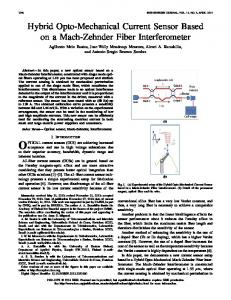
where fO is the output frequency; D is the output frequency for dark condition (Ee = 0); Re is the device responsivity for a given wavelength of light given in kHz/(mW/cm2); Ee is the incident irradiance in mW/cm2; fD is an output frequency resulting from leakage currents. As shown in the equation above, this frequency represents a light-independent term in the total output frequency fO. At very low light levels, this dark frequency can be a significant portion of fO. The dark frequency is temperature dependent [3]. Since the signal is in the form of a frequency, dynamic range is not limited by supply voltage and noise. Sensitivity of the device is maximized by a large detector area and precision input circuitry. Once converted to a frequency, the signal is virtually noise immune and may be transmitted over cables from remote sensors to other parts of system. Isolation is easily accomplished with optical couplers or transformers. Being a pulse data form, the signals of several sensors may be easily multiplexed into one microcontroller or counter using digital logic. Integration of the frequency signal is easily performed in order to eliminate low frequency interference or to measure long-term light exposure rates [2]. When a very high resolution light measurement is required, and speed is not critical, frequency or pulse counting technique would be used (the standard counting technique). This can be accomplished by counting pulses for a defined gate time. Relatively fast light measurements can be made by measuring the output period (indirect counting technique), or alternatively, pulse width [4]. One of possible light-to-digital converter based on the discrete logical components is shown in Figure 1 [2]. But such solution is relatively complex and needs more hardware.
327
Sensors & Transducers Magazine (S&T e-Digest), Vol.56, Issue 6, June 2005, pp.326-334
Fig. 1. Light-to-Digital Converter.
The output of the light-to-frequency converters may be also directly interfaced with microcontrollers. The particular choice of microcontroller will depend upon required performance and operating range of the light sensing function, as well as other system requirements. Performance factors such as accuracy and measurement range depend upon available embedded peripherals and operation speed of the microcontroller. Microcontrollers can provide a convenient direct sensor interface for frequency output light sensors in order to produce low cost digital output sensors. Such solution needs minimum hardware and external connections. The direct use of microcontrollers in the measurement chain offers simple, low-cost solutions yet introduces additional error components due to so-called programdependent or software-related effects [5, 6] and is not a simple time-window counting task. From the other side taking into account very wide output frequency range of light-to-frequency converters (from 1 Hz up to 1MHz) no one from classical methods can be used in this full range because of dependence of quantization error on frequency and its very high value at the beginning (for frequency measurement) and at the end (for period measurement) of range. In case of the use any from advanced measurement method for frequency (period) including the combined conversion method [3], a customer must buy a license.
2. Digital Color and Light Sensors with Direct Interface to UFDC-1 In order to eliminate such design problem, the Universal Frequency-to-Digital Converter (UFDC-1) was designed and introduced to the market by SWP, Inc. (Toronto, Canada) [7]. This programmable IC is intending for any frequency output sensors, working in the wide frequency range and can be used for digital light (or color) sensors and data acquisition systems design. The UFDC-1 is based on four novel advanced measurement methods for frequency-time parameters and has such significant benefits as the constant programmable conversion error in all frequency range and non-redundant conversion time. So, in other words it can be used for both designs in the same time: for maximum resolution and accuracy as well as for maximum data-acquisition rate. 2.1 Color-to-Digital Converter The programmable color-to-frequency converter TCS230 with the direct interface to the universal frequency-to-digital converter interface is shown in Figure 2. This circuit diagram is corresponds to the 100 % scaling mode for TCS230 (S0, S1 =1) and clear photodiode type (no filter, S2=1, S3=0). Powersupply lines must be decoupled by a 0.01-µF to 0.1-µF capacitor with short leads mounted close to the device package. 328
Sensors & Transducers Magazine (S&T e-Digest), Vol.56, Issue 6, June 2005, pp.326-334
The converter’s inputs S0, S1, S2, S3 and OE can be also controlled by the UFDC-1 but in this case a custom design UFDC should be ordered.
Fig. 2. Color Detector TCS230 with Direct Interface to UFDC-1.
The UFDC-1 can work in one of three possible communication modes: RS-232 (slave and master), SPI and I2C. A communication interface type can be automatically selected according to the circuit connection [8]. Working in the master mode (unidirectional data transfer) the UDFC-1 can be used in digital sensors design. In the master mode, the conversion accuracy and measurement mode should be selected by external jumpers. In the slave mode (with an external microcontroller), all measuring modes and programmed accuracy can be set up by a data bus or through communication I/O ports of master microcontroller. This allows us use the UFDC-1 as a simple peripheral circuit for a microcontroller. The UFDC-1 can be also controlled by PC through a COM port. It is useful for data acquisition systems design. Two different frequency output sensors can be connected to one UFDC-1. A bidirectional data exchange is possible with any of three interfaces RS-232, SPI or I2C. 2.2 Light-to-Digital Converters The interfacing of programmable light-to-digital converters as TSL230R and TSL230RD to the UFDC-1 is the same as it is shown in Figure 2. The difference is only in inputs assignment. So, the inputs S0 and S1 are sensitivity-select inputs and S2, S3 - fo scaling-select inputs. The light-to-frequency converters TSL235R, TSL237 and TSL245R with the direct interface to the universal frequency-to-digital converter interface is shown in Figure 3 and the light-to-frequency converter TSL 237T interfacing is shown in Figure 4. Power-supply lines must be decoupled by a 0.01-µF to 0.1-µF capacitor with short leads placed close to the devices. The comparative system performance summary with some popular microcontrollers and the UFDC-1 is shown in Table 2. Taking into account the converters’ nonlinearity error 0.2 ÷ 1 % FS and absolute output frequency tolerance of ± 5 % the UFDC-1 conversion error should be chosen 1 %. Appropriate commands (RS-232 interface) for the UFDC-1 operation is shown in Figure 5. 329
Sensors & Transducers Magazine (S&T e-Digest), Vol.56, Issue 6, June 2005, pp.326-334
Fig. 3. Light Detectors TSL235R, TSL237 and TSL245R with Direct Interface to UFDC-1.
Fig. 4. Light Detector TSL237T with Direct Interface to UFDC-1.
Table.2. The comparative system performance summary with some popular microcontrollers and the UFDC-1. Device TMC370 MC68HC11 PIC16C5x UFDC-1
Resolution 16 bit 16-bit 8-bit 16-bit
Period Measurement Min. Frequency Max. Frequency 76 Hz 92 kHz 46 Hz 111 kHz 4.8 kHz 1 MHz 0.05 Hz 7.5 MHz
Measuring Time 29.3 µs -13.1 ms 15.3 µs - 21.8 ms 1 µs - 210 µs 0.2 ms + (0÷Tx)
330
Sensors & Transducers Magazine (S&T e-Digest), Vol.56, Issue 6, June 2005, pp.326-334
Example 1: >M0 >A0 >S >R 1000.674946004319 >
; Frequency measurement initialization ; 1 % conversion error set up ; Start a measurement ; Read a result ; Measurement result indication
Fig. 5. Appropriate Commands (RS-232 interface) for the UFDC-1 Operation with TAOS Light- and Color-to-Frequency Converters
3. Multiparameters Sensor Interfacing Another interesting example of intelligent opto sensors with frequency output is the integrated smart optical sensors developed in Delft University of Technology [9]. The readout of photodiodes in the silicon takes place in such a way that pulse series are generated with the pulse frequency proportional to the optical intensity (luminance) and the duty cycle to the colour (chrominance). The colour information is obtained using the wavelength dependence of the absorption coefficient in the silicon in the optical part of the spectrum, so no filters are required. Such sensing element also can be interfacing to the UFDC-1 in order to produce digital multiparameters (light and color) sensor. The possible diagram of such perspective sensor is shown in Figure 6 and appropriate the UFDC-1 commands – in Figure 7.
Fig. 6. Multiparameters Opto Sensors with Direct Interface to UFDC-1.
Two UFDC’s input are using in this interfacing: the duty cycle is measuring at the fist input and frequency at the second input. The digital opto sensors can be used for different data loggers applications, proximity detection, color classification systems, oximeters, light parameters monitoring and control, water turbidity measurement, flame control, fluid absorption measurement, paper handling, exposure control, general visual process control, etc. 331
Sensors & Transducers Magazine (S&T e-Digest), Vol.56, Issue 6, June 2005, pp.326-334
Example 2: >M4 ; Duty-cycle measurement initialization >S ; Start a measurement >R ; Read a result 60.9786 ; Duty-cycle measurement result indication >ME ; Frequency measurement initialization on the second input FX2 >AX ; Appropriate ‘X’ conversion error set up >S ; Start a measurement >R ; Read a result 100.578698673245 ; Frequency measurement result indication > Fig. 7. Appropriate Commands (RS-232 interface) for the UFDC-1 Operation with Multiparameters Opto Sensor
4. Bus Capabilities Due to the UFDC-1 bus capabilities, digital sensors with 2-wire I2C and 3-wire SPI bus can be easily created. Working with the I2C the UFDC-1 can have one of 8 possible addresses that can be setup by its A0-A2 pins. The absolute address of a device has the following format 1110 [8]. The circuit diagram for the 2-wire I2C interface to different TAOS opto sensors (for example, light, infrared and color) is shown in Figure 8. Appropriate commands (analog to Example 1) is shown in Figure 9.
Fig. 8. 2-wire I2C Interface to Different TAOS Opto Sensors. Example 3:
; Frequency measurement initialization ; 1 % conversion error set up ; Start a measurement ; Get measurement result in BCD format.
Returns sign byte and 12 bytes of result in BCD code: , where - sign of result 0x20 (space char) for positive result 0x2D (minus char) for negative result; - byte n of integer part of result; - byte n of fractional part of result; Fig. 9. Appropriate Commands (I2C - interface) for the UFDC-1 Operation with TAOS Sensors. 332
Sensors & Transducers Magazine (S&T e-Digest), Vol.56, Issue 6, June 2005, pp.326-334
I2C is a 2-wire, half-duplex, serial bus, as shown in Figure 1. The two I2C signals are serial clock (SCL) and serial data (SDA). Both lines are bidirectional and must be connected to Vcc via pull-up resistors. The SPI is full-duplex, (3+n)-wire serial busses. (n is the number of slaves). The circuit diagram for the 3-wire SPI is shown in Figure 10. In single master, multiple slave configurations, as shown in Figure 10, each slave device requires a dedicated Slave Select (SS) signal, which is created by the master using standard I/O pins.
Fig.10. Single Master, Multiple Slave SPI Implementation.
Appropriate commands for SPI communication to the UFDC-1 are the same as it was shown in Figure 9 (Example 3). SPI's full duplex capability and fast data rates make those interfaces very efficient and simple for single master - single slave applications. In practical applications, the requirement for dedicated slave select signals severely limits the number of slave devices that can be connected to a microcontroller. SPI is better suited than I2C for applications that are naturally thought of as data streams (as opposed to reading and writing addressed locations in a slave device). An example of a "stream" application is data communication between microprocessors or digital signal processors. Another is data transfer from analog-to-digital converters. SPI can also achieve significantly higher data rates than I2C. It really gains efficiency in applications that take advantage of its duplex capability, such as the communication between a "codec" (coder-decoder) and a digital signal processor, which consists of simultaneously sending samples in and out. I2C bus has more complex protocol put it at a disadvantage in single master-single slave applications. Its weakness turns into strength if a larger number of slave devices needs to be connected or a multimaster system is needed. 333
Sensors & Transducers Magazine (S&T e-Digest), Vol.56, Issue 6, June 2005, pp.326-334
The UFDC-1 works well with these both buses and due to this ability different frequency output TAOS opto sensors can be connected to these popular in sensors world buses.
5. Conclusions The described design approach for digital opto sensors based on the UFDC-1 lets significantly simplify the design process, reduce time to market and production price and produce color and light sensors as well as multiparamters sensors with high metrological performances. The UFDC-1 can be used for both designs in the same time: for maximum resolution and accuracy as well as for maximum dataacquisition rate. In comparison with the direct microcontroller interfacing the proposed approach also lets to eliminate many design problems connected with the use of advanced measurement methods for frequency measurements, microcontroller choice, its programming and additional error components due to socalled program-dependent or software-related effects.
References [1]. Http://www.taosinc.com/category.asp?cateid=2 [2]. Intelligent Opto Sensor Data Book. Texas Instruments, SOYDE02B, 1996. [3]. TSL230RD, TSL230ARD, TSL230BRD Programmable Light-to-frequency Converters, TAOS054D December 2004 [4]. Kirianaki N.V., Yurish S.Y., Shpak N.O., Deynega V.P., Data Acquisition and Signal Processing for Smart Sensors, John Wiley & Sons, 2002 [5]. Yurish S.Y., Program-oriented Methods and Measuring Instruments for Frequency-Time Parameters of Electric Signals, PhD Thesis, State University Lviv Polytechnic Lviv, 1997 (In Ukrainian). [6]. Reverter F., Microcontroller-based Interfaces for Quasi-Digital Sensors, PhD Thesis, Technical University of Catalonia (UPC Barcelona, Spain), 2004 [7]. Sergey Y. Yurish, Nikolay V. Kirianaki, Ramon Pallàs-Areny, Universal Frequency-to-Digital Converter for Quasi-Digital and Smart Sensors: Specifications and Applications, Sensor Review, Vol. 25, Number 2, 2005, pp.92-99. [8]. Universal Frequency-to-Digital Converter (UFDC-1), Specification and Application Note, 2004. http://www.sensorsportal.com/HTML/E-SHOP/PRODUCTS_4/UFDC_1.htm [9]. G. de Graaf, Wolfenbuttel R.F., Light-to-Frequency Converter Using Integrated Mode Photodiodes, in Proceedings of IMTC’96; 1996 June 4-6; Brussels, Belgium, pp.1072-1075. ___________________
2005 Copyright ©, International Frequency Sensor Association (IFSA). All rights reserved. (http://www.sensorsportal.com) 334