Therefore inter-camera color calibration is important for object ..... i and h1 j ..hk j for k objects for camera pair Ci, Cj. 2) Find the mean value of Bm of only those histograms that have a significant ... 1http : //www.cvg.rdg.ac.uk/P ET S2009/a.html.
Inter-Camera Color Calibration for Object Re-identification and Tracking Atif Ilyas, Mihaela Scuturici, Serge Miguet Universit´e de Lyon, CNRS Universit´e Lumi`ere Lyon 2, LIRIS, UMR5205 Lyon, France {Atif.Ilyas, Mihaela.Scuturici, Serge.Miguet}@univ-lyon2.fr
Abstract—Object re-identification and tracking in nonoverlapping cameras is a challenging problem due to the variation of the object’s appearance, linked to the different view angle, distance and color variation in different cameras. We present a computationally efficient real time human tracking algorithm, which can track objects inside the field of view (FOV) of a camera, re-identify objects that exit and then return in a same or in a different camera FOV. Object appearance in several cameras may be very different due to illumination conditions, camera gain, focus, focal length etc. Therefore inter-camera color calibration is important for object re-identification before applying object recognition features. We compare different existing color calibration methods and evaluate their color brightness transfer function (BTF) using Receiver Operating Characteristic (ROC) curve. We propose some modifications in cumulative brightness transfer function (CBTF) which significantly improve the objects re-identification in non-overlapping multi camera environment. Keywords-video surveillance; brightness transfer function; color calibration; object tracking; object identification;
I. I NTRODUCTION Active surveillance systems are used to detect unauthorized or suspicious behaviors and then register the activities of objects and their trajectories. In realistic scenario, large area surveillance is done by using non overlapping cameras. In this paper, we investigate object identification and tracking in multiple non overlapping cameras separated by blind regions. We have previously proposed [1] an appearance based object tracking algorithm having the ability to reidentify the moving objects. Our tracking process is applied independently to each single camera, but the objects features are stored in a common object database which allows object recognition when the object exits from the field of view of one camera and then enters in another cameras. The system performance is not affected by the distance between moving objects and cameras, (the object may be close to the camera - big object - or far away - small object) and it can also be applied to indoor as well as outdoor scenes. Objects colors appearance are very different in different cameras due to cameras model, gain and the region where they are installed. Due to the above discussed reasons, cameras color calibration is essential. Existing algorithms are unable to perform reliable real time object recognition when objects are deformable and exit
and re-enter in the field of view of the cameras. Some of extensive survey work on the deformable object detection, recognition and tracking are presented in [2]–[4]. In these surveys, author discuss various algorithms from each class and explain their advantages and limitations. Some related work on 1-D color appearance models are presented in [5]–[7]. K. Sato et al. [5] discuss many aspects of object tracking and interaction. They use 1-D appearance model with geometrical features like horizontal projection and horizontal size for object matching. Therefore, it is less reliable for human tracking as the apparent size can be very different in different frames or in different camera’s field of view. A. Elgammal et al. [6] divide objects height into three parts: head, torso and bottom. Division of object height into only three part is not sufficient to capture the object’s vertical color variation. A. Mittal et al. [7] use overlapping multi-camera system for human tracking. They divide object height into h slices and model each slice with a Gaussian kernel as explained in [6]. Using of N Gaussians for each h slices increases its computational cost. Inter-camera color calibration plays a vital role in appearance based object identification and tracking. Porikli et al [8] compute the BTF for each camera pair before installing them for surveillance. They claim that once this mapping is calculated then object correspondence is reduced to transformed histograms. But this assumption is not sufficient, because these cameras might be installed in a regions having different illumination than the color calibrated environment. Javed et al [9] propose a subspace based color brightness transfer function. They use a probabilistic PCA for object matching. They combine the color information with object motion and show the superiority of the combined approach. But in our experiments, we don’t have the information of camera position and many entry points are possible. Concepts of cumulative brightness transfer function (CBTF) and mean brightness transfer function (MBTF) are discussed in details in [10], [11]. Prosser et al [10] show in their experiments that CBTF is better than MBTF which seems to be contradicted the results of D’orazio et al [11]. In our experiments explain in section IV we find that MBTF and CBTF result are not significantly different. In section II, we presents in details the recognition features and a method of object identification and tracking. In section
III, we will discuss the two existing techniques for intercamera color calibration and propose a modification in the CBTF technique. In section IV, we discuss the results of our algorithm and compare it with other existing techniques in terms of ROC curve between precision and recall performance of re-identification, with and without color calibration. Section V presents the conclusion and some future works. II. O BJECT RECOGNITION AND TRACKING In previous work [1], we introduced a 1-D color based appearance model which preserves objects spatio-color information. This feature allows recognizing an object that exits and re-enters in the field of view of different cameras. We use a main database to store all detected objects. Each object that enters for the first time in any of the cameras field of view is stored once in a database. The database stores only invariant features (1D appearance model) of each object which is useful for the object recognition process. Position P = [x, y] and velocity V = [vx , vy ] of object are commonly used in a single camera or calibrated multi-cameras as motion features. These features helps to recognize similar objects in a scene if they are far or moving with different velocities from each other. A. Object Vertical Feature The idea of an 1-D appearance model is to describe each object by a vector representing its projection on the main axis (head-foot axis) of the object, which will be considered as a vertical in the article. Because, we mainly address person recognition in a video surveillance systems. This vector is determined with a predefined height h and each value of y (y=1...h) is represented by the most representative color of the horizontal projection of this specified slice of the object. Vertical feature computation algorithm 1) For each object fix the height value = h, where h is a constant number . 2) Extract segmented object (person) from image. 3) Rescale the object’s height h0 to h: if h0 < h then use a bicubic interpolation else use Gaussian kernel. 4) For each horizontal slice at level y0 do:
5) Find the most representative color slice y0 . (1)
V F (y0 ) = ξ (I(x, y0 ))
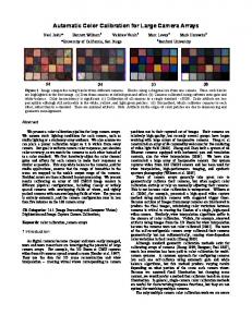
VF is a vector consisting of h elements for each color channel. Possible choices for ξ (I(x, y0 )) are mean and median color value of each color channel taken individually, or a particular color value minimizing a given criterion such as the quadratic sum of the distances in RGB color space. We performed experiments on ξ (I(x, y0 )) and found that mean and median color value give the best performance. Sometimes, we have the risk to lose the true object color if the horizontal projections of the object at some height slice have two or more very different colors. We also tried to use texture information, the results are not significantly improved due to poor quality of surveillance videos which don’t contain adequate level of detail. Fig. 1.a illustrates how large or small object are resized or re sampled to the predefined height h. Fig. 1.b shows some sample objects and their VF representation. VF preserves some vertical texture information, face and hair color. VF technique is also computationally efficient and needs low memory storage. B. Object position prediction Object position prediction helps to estimate future objects position in the video frames and also can give some objectobject occlusion prediction [1]. We use Kalman filter [12] to calculate the probabilistic position and to detect occlusion of objects in next frame. The Newtonian equation of motion allows to find the object position in the next frame. We model our states as a 4-D vector by using the object position h(xi , yi ) and its ivelocity (vxi , vyi ) at discrete time t i , v i . Dynamic equations of the system by Xt = xit , yti , vxt yt are described by the following non-linear equations:
Xt+1
ai
i ∆t + xt ∆t2 xit + vxt 2 i y i + v i ∆t + ayt ∆t2 yt = t 2 i + ai ∆t vxt xt
(2)
i + ai ∆t vyt yt
The non-linearity of object motion, the acceleration � � aixt , aiyt , is modeled by a process noise Wt . ∆t is the time difference between two consecutive frames. The matrix form of (2) is: Xt+1 = At+1,t Xt + Wt (3) where At+1,t is the state transition matrix which links next position to current object position. For more details see Bishop et al. [13]. C. Feature matching and object tracking
Figure 1.
Sample objects, their VF representation and scaling
In order to match objects features, we use the Mahalanobis distance. It differs from the euclidean distance by its scale invariance and it also takes into account the objects color
variance in the database. Mahalanobis formula for VF is represented as 1
D V F ,V F
2
�
v u h 3 uX X =t y=1 ch=1
V F 1 (y, ch) − V F 2 (y, ch) σ(y,ch)
!2
(4)
2 σ(y,ch)
is the color variance of each element of vector VF in the database containing T objects. Here we consider two cases. In a first case, we suppose that current object is previously present in the camera’s field of view. We use (4) to find distances Dn between features of current object Oc and previous frame’s objects On by using (5). Dn (Oc , On ) = D (V F c , V F n ) + D (P c , P n ) + D (V c , V n )
(5)
Where as n= 1...q and q ≤ T and we assume D1 ≤ D2 ≤ ..Dq and we select only distances (D1 , D2 ..Dl ) ≤ Dref . Dref is a similarity threshold. Only objects which are more similar in their colors appearance with Oc are selected. Find only one match object may be false matching due to the possibility of wrong object segmentation in current frame or change of object view angle in camera. Get predicted positions Pp1 , Pp2 ...Ppl for the objects O1 ...Ol for current frame. Find euclidean distance Demin (Oc , Od ) between the current position P c of object Oc and predicted positions Pp1 , Pp2 ...Ppl . If Demin < Dth then update the position, velocity and area of the match object in database and cache. VF is updated as: V F d = αV F d + (1 − α)V F c and α is a learning rate. If Demin > Dth or current object is not present in previous frame then Dg is selected by finding the closest match g of current object c from the database containing T objects on the base of the vertical feature only. g = arg min (D (V F c , V F r )) ; r = 1.....T
(6)
Equation (6) is useful if object exits and re-enters in a same camera or in the FOV of another camera. In this cases motion features and Kalman prediction is not useful as it is possible that the object exits from one side and enters in a camera FOV from some other side. If Dg (Oc , Og ) > Dref then a new object is created in the database. Selection of Dref is important as smaller value of Dref increase false negatives and higher value of Dref increase false positives (see the section IV). III. I NTER -C AMERA C OLOR C ALIBRATION Color calibration in non-overlapping environments is necessary as our recognition feature is mainly based on a color appearance model. Object appearance in different cameras may be very different even in controlled environment (indoor regions). Some important parameters influencing object’s color appearance are camera gain, focal length, aperture size, illumination conditions and scene geometry. Mapping function of one camera color space to a color space of another cameras is called Brightness Transfer Function (BTF).
The two commonly used techniques are : mean brightness transfer function (MBTF) and cumulative brightness transfer function (CBTF). Brightness transfer function between two cameras is calculated during a training phase. During this stage we assume that we know the objects correspondence from C i to C j . Let us assume object O enters in the camera C i and after exiting C i the same object enter in the camera C j . Normalized histograms for each channel is calculated for the two cameras and a BTF fi,j between the cameras is computed from the two cumulative histograms. In the following subsections for simplicity we use histograms instead of RGB histograms and we use the same algorithm for calculating each color channel of objects. The algorithm for finding the BTF is explained in steps 1-3 as following: BTF algorithm 1) Compute the normalized histograms I i (Bm ) and I j (Bm ) for each object of camera C i and C j , where B1 , ...Bm ...B256 are brightness values of each of histogram bins. 2) Find the cumulative histogram Hi (Bm ) and Hj (Bm ) as : m X H (Bm ) = I(Bk ) (7) k=1
3) Hi (Bm ) and Hj (Bm ) are normalized cumulative histograms for the same object O. Hi (Bm ) = Hj (fi,j (Bm )) and the BTF mapping function is fi,j (Bm ) = Hj−1 (Hi (Bm ))
(8)
In the following subsections, we will explain the method to calculate BTF fi,j for MBTF, CBTF and our modified CBTF (MCBTF). A. Mean Brightness Transfer Function In mean brightness transfer function (MBTF) the fi,j between two cameras C i and C j is obtained by calculating BTF for each object in camera pair C i −C j . After calculating BTF for all objects images, the mean BTF is calculated from these BTF. The steps of MBTF are presented bellow: 1) Do the steps 1-3 explained above for each object appearing in camera pair C i − C j . 2) Find the BTF for each of training objects pair. 3) Find the MBTF by taking the average of all the BTF. In general one object has only a limited number of colors, that is why each BTF curve gives better responses for the histogram regions where it is representative of objects colors. When we take the mean of all the BTF then the histogram regions having more colors represent a true correspondence for camera pair C i − C j but other regions lose informations due to the averaging process. B. Cumulative Brightness Transfer Function MBTF loses inter-camera color informations which are not present in majority of objects. This increases the problem
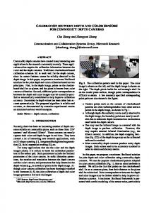
Figure 2.
Brightness Transfer function (BTF) for our method (MCBTF), CBTF and MBTF are shown for red, green and blue channel respectively.
of object re-identification when the object exits from one camera and enters the field of view of another camera. If BTF is not properly calculated, then the object color mapping from one camera to the other one might be incorrect. This becomes the reason of false object identification. To overcome this problem, the cumulative brightness function is proposed in [10]. The algorithm is explained bellow: 1) Compute the histograms h1i ..hki and h1j ..hkj for k objects for camera pair C i , C j . 2) Accumulate the brightness values of the histograms h1i ..hki for camera C i and the histograms h1j ..hkj for camera C j and compute the cumulative histograms Hi (Bm ) and Hj (Bm ) as: H (Bm ) =
m X k X
hl (Bk )
a) Find the normalized mean histogram hi and hj for camera C i and C j by using (10): Kim =
Cumulative histogram technique explained in [10] claims that it solves the problem of MBTF which lose color information that are not present in the majority of objects. But in CBTF algorithm, it is clear from step 2 and 3 of subsection III-B that they accumulate all the histograms for the camera C i and C j respectively and then normalize the cumulative histograms for each camera. But in many cases, objects histogram do not have contributions to all the histogram bins. That is why if we take sum of the Bm for all histograms and normalize its value by the total number of pixels in the training set, then a lot of information is lost. We propose to modify the steps 1, 2 and 3 of CBTF to improve its performance. The steps of our MCBTF are presented bellow: 1) Compute the histograms h1i ..hki and h1j ..hkj for k objects for camera pair C i , C j 2) Find the mean value of Bm of only those histograms that have a significant contribution to Bm . This is done as folows:
(10)
is the total set of histogram indices and Kim is the subset of I such that the selected histograms have a significant contribution to Bm . m = [1, 2...256] are total numbers of bins. Θ is basically minimum value of bin Bm for being considered on its significance. The threshold value of Θ is selected in training period. Our experiments show that a typical value of Θ between 3 and 5 gives good results in most situations. The number of elements of Kim will be noted as #Kim b) The average value of bin Bm can then be computed as:
(9)
C. Modified Cumulative Brightness Transfer Function
o k ∈ I; hki (Bm ) > Θ ;
I = [1..k]
k=1 l=1
3) Normalize the cumulative histogram Hi (Bm ) and Hj (Bm ) by the total numbers of pixels in training set for C i and C j . 4) Calculate BTF by using equation (8).
n
P hi (Bm ) =
k∈Kim
hki (Bm )
#Kim
(11)
3) Find the cumulative histogram Hi (Bm ) and Hj (Bm ) by using (7) 4) Calculate BTF by using (8). IV. E XPERIMENTAL RESULTS We have performed two series of experiments. We will first discuss the object tracking performance of our experiments in details. We will then explain the results of object re-identification, with and without using color calibration techniques in multi camera environments. We compare our algorithm with two other methods: the first one is based on object motion estimated by Kalman filter and the second one is appearance and color based mean shift algorithm. We evaluate the tracking results on the well known PETS1 , CAVIAR2 and VISOR3 benchmark datasets. We have taken 7410 frames from 15 videos having at least one object present. These videos have many challenges like shadows, occlusions, irregular luminosity, object’s shape and size evolution, re-entrance of objects and low video quality. We compare each object’s position in 1 http
: //www.cvg.rdg.ac.uk/P ET S2009/a.html : //homepages.inf.ed.ac.uk/rbf /CAV IARDAT A1 3 http : //www.openvisor.org/video categories.asp 2 http
Table I C OMPARISON TABLE OF DIFFERENT TRACKING TECHNIQUES ON STANDARD DATASETS
Dataset CAVIAR VISOR PETS Overall TR (fps)
Kalman [12] 93.27% 81.27% 73.18% 81.57% 85.63
Mean shift [14] 85.64% 64.70% 67.04% 70.86% 7.18
Our Algorithm 96.72% 89.02% 91.355% 91.97% 39.32
the video with a ground truth obtained by manual labeling of objects, and distinguish them for a visual control by drawing a rectangle around them using different colors. Fig. 3 shows that we recognize objects in video sequences even with the change of view angle, similar clothes color and also under occlusion. Table I shows that Kalman filter gives good results on CAVIAR dataset due to less objects occlusion and interaction. Simple motion based technique can track the object successfully in this situation. Object color appearance base technique is unable to give good results due to color similarity between object-object and object-background. VISOR videos have small and large object sizes, similar objects, low and high video quality, uneven luminosity in video frames. Mean shift gives really poor results and Kalman filter fails to track objects due to occlusions. Kalman filter is unable to distinguish if the same or a different object enters in the scene as it only uses motion features. Our algorithm gives satisfactory results except for videos having a very low color quality. PETS 2009 database have many challenges. There are many entry points, several occlusions of more than two persons. Many persons have similar clothes and they occlude each other. One person exits and an other person having the same clothes color enters at the same position in the scene. The same person exits from one side and enters from opposite side. Our algorithm is able to track the objects under above defined cases. In table I, the second last entry gives the recognition percentage of total objects present in all frames. Our algorithm success rate is 92%, Kalman has 82% and mean shift has last position having score 71%. Our proposed algorithm uses color, motion and spatial information that is why it supperseeds both Kalman and mean shift. Last entry of table 1 is tracking rate (TR). We track 15-20 objects in images sequences on a laptop having a Core Duo processor (T2350) with 1.86 GHz clockrate, where as video frames size is 320 x 240. Our algorithm is faster than mean shift
Figure 3.
Objects recognition and tracking in PETS database
but slower than plain Kalman filter because Kalman filter is also integrated in our algorithm. In the second series of experiments we have installed three cameras of different models (Fuji, Sony and JVC) with no overlapping field of view. We set camera C1 as reference and others cameras C2 and C3 are calibrated by finding their BTF f2,1 and f3,1 , by using the three methodologies explained in section III. In the training phase we use 10 images/object for five objects present in the sequences for each camera. Illumination conditions and colors are different for these cameras. We plot the BTF of the C1-C2 pair of cameras for R, G and B channels. Fig.2 shows that our MCBTF works better and it maps low intensity pixels to higher intensities pixels after intensity value 100 for camera C2 which has less light intensity. This is the point where our modification works better than CBTF and MBTF as in our experiments many persons have dark clothes. Histograms of every objects do not have contributions to all the bins. If we take the same method of CBTF, then BTF for pixels having intensities higher than 100 are mapped to lower values which decreases the performance of object matching like CBTF and MBTF. In second step, we allowed 12 objects to enter and exit from FOV of one camera to another camera more than 30 times from different direction in random order. In Fig. 4 objects are passing through in FOV of cameras C1, C2 and C3 in different time sequences and our algorithm draws the bounding box around these objects which remains constant in all camera even with the change of size, camera view angle, illumination changes and different color appearance. We do object re-identification when they enter in the field of view of another camera. We plot ROC curve between precision (PR) and Recall (RE) for a set of values of Dref . We fix the value of α = 0.97 and Dth = 60 pixels and we change the value of Dref from 8 to 12. PR and RE of object re-identification for each algorithm is calculated by using equations (12) and (13). PR =
TP TP + FP
(12)
RE =
TP TP + FN
(13)
If an old label is correctly assigned to an object, or created for a new object, then it is considered as a true positive (TP). If an old label is assigned to a wrong object, then it is
Figure 4. Objects re-identification in non-overlapping multi camera environment
R EFERENCES [1] A. Ilyas, M. Scuturici, and S. Miguet, “A combined motion and appearance model for human tracking in multiple camera environment,” in ICET2010, 2010 (to appear). [2] A. Yilmaz, O. Javed, and M. Shah, “Object tracking: A survey,” ACM Comput. Surv., vol. 38, no. 4, p. 13, 2006. [3] M. Enzweiler and D. Gavrila, “Monocular pedestrian detection: Survey and experiments,” PAMI, vol. 31, no. 12, pp. 2179–2195, 2009. Figure 5. Object re-identification ROC curve between Precision and recall using with and without color calibration (WCC).
[4] D. Geronimo, A. M. Lopez, A. D. Sappa, and T. Graf, “Survey of pedestrian detection for advanced driver assistance systems,” PAMI, vol. 32, no. 2, pp. 1239–1258, 2010.
considered as a false positive (FP). If a new label is created for an already labeled object, then it is considered as a false negative (FN). Fig. 5 illustrates that our modification to CBTF increases significantly the object re-identification performance, both in terms of precision and of recall. MCBTF has higher value of precision and recall than all the three other techniques. In ROC curves, performance of CBTF and MBTF are comparable, without clear advantage of one approach in front of the other. This corroborates the contrasted results presented by [10] and [11]. The three color calibration techniques show nevertheless a slight improvement as compared to the basic approach that does not calibrate cameras (WCC). This latter method produces more FP specially in camera 2 which is installed in the region having lower illumination. Hence its re-identification results are worse than any of the techniques that use color calibration. We can then conclude from our object re-identification results that MCBTF gives re-identification performance significantly better than CBTF and MBTF.
[5] K. Sato and J. Aggarwal, “Temporal spatio-velocity transform and its application to tracking and interaction,” CVIU, vol. 96, no. 2, pp. 100–128, 2004.
V. C ONCLUSION AND FUTURE WORKS We extended our simple 1-D appearance model for object tracking and re-identification in non-overlapping multicamera video surveillance system. We proposed the modification to the well known CBTF color calibration technique and showed a significant improvement in tracking and reidentification. In general, the algorithm gives satisfactory results, but there are situations in which it fails: if object’s height is smaller than 30 pixels or in the case of very low video quality. Modified cumulative brightness technique works satisfactory even for a new objects which have not been used during the training time. In future works, we are planning to propose BTF updating strategies, in order to cancel out the effects of changes in illumination conditions after the training time.
[6] A. Elgammal, R. Duraiswami, and L. Davis, “Efficient kernel density estimation using the fast gauss transform with applications to color modeling and tracking,” PAMI, vol. 25, no. 11, pp. 1499–1504, 2003. [7] A. Mittal and L. Davis, “M2tracker: A multi-view approach to segmenting and tracking people in a cluttered scene,” IJCV, vol. 51, no. 3, pp. 189–203, 2003. [8] F. Porikli and A. Divakaran, “Multi-camera calibration, object tracking and query generation,” in ICME ’03:, 2003, pp. 653– 656. [9] O. Javed, K. Shafique, Z. Rasheed, and M. Shah, “Modeling inter-camera space-time and appearance relationships for tracking across non-overlapping views,” Comput. Vis. Image Underst., vol. 109, no. 2, pp. 146–162, 2008. [10] B. Prosser, S. Gong, and T. Xiang, “Multi-camera matching using bi-directional cumulative brightness transfer functions,” in BMVC08, 2008. [11] T. DOrazio, P. Mazzeo, and P. Spagnolo, “Color brightness transfer function evaluation for non overlapping multi camera tracking,” in ICDS ’09:, 2009. [12] R. Kalman, “A new approach to linear filtering and prediction problems,” T-ASME, pp. 35–45, 1960. [13] G. Welch and G. Bishop, An Introduction to the Kalman Filter. Chapel Hill, NC, USA: University of North Carolina at Chapel Hill, 1995. [14] D. Comaniciu, V. Ramesh, and P. Meer, “Real-time tracking of non rigid objects using mean shift,” in CVPR, 2000, pp. 142–149.