iWISE: Inter-router Wireless Scalable Express Channels for Network-on-Chips (NoCs) Architecture Dominic DiTomaso, Avinash Kodi, Savas Kaya, and David Matolak School of Electrical Engineering and Computer Science Ohio University, Athens, OH 45701 E-mail: dd292006, kodi, kaya,
[email protected] Abstract—Network-on-Chips (NoCs) paradigm is fast becoming a defacto standard for designing communication infrastructure for multicores with the dual goals of reducing power consumption while improving performance. However, research has shown that power consumption and wiring complexity will be two of the major constraints that will hinder the growth of future NoCs architecture. This has resulted in the investigation of emerging technologies and devices to alleviate the power and performance bottleneck in NoCs. In this paper, we propose iWISE, an inter-router wireless scalable express channels for NoCs architecture that minimizes the power consumption via hybrid wireless communication channels, reduces the area overhead with smaller routers and shared buffers, and improves performance by minimizing the hop count. We compared our network to leading electrical and wireless topologies such as mesh, concentrated mesh, flattened butterfly and other wireless hybrid topologies. Our simulation results on real applications such as Splash-2, PARSEC, and SPEC2006 for 64 core architectures indicate that we save 2X power and 2X area while improving performance significantly. We show that iWISE can be further scaled to 256 cores while achieving a 2.5X performance increase and saving of 2X power when compared to other wireless networks on synthetic workloads.
I. I NTRODUCTION As silicon technology scales, chip designs are moving towards integrating a large number of cores on a single chip allowing the number of transistors to double every 18 months. Due to the shared nature of bus networks, both power consumption and latency become a bottleneck. These limitations have motivated designers to move towards Network-on-Chip (NoC) architectures [1]. Traditional NoC designs consist of metallic interconnects arranged in topologies such as a 2D mesh or torus. However, with technology scaling, global interconnects using metallic NoCs increase wire delays and power consumption. Together with the increased complexity of interconnect routing and multi-hop communication, the high latency and power dissipation will have a significant impact on the overall performance of the network [2]. On the other hand, intermediate wires are still highly effective and suitable for short distances. The vast improvements in complementary metal-oxide-semiconductor (CMOS) technology have led to wires with only 0.18 pJ/bit of energy consumption at 1 mm for a 32 nm technology design [3]. For long distances, wireless interconnects can alleviate the power while providing high bandwidth and low latency communications [4], [5]. Wireless communication is an established technology that has been implemented in various applications and devices, including cellular phones, wireless networking,
wireless mice and keyboards. These implementations have illustrated the feasibility of wireless communication being compatible with the already existing CMOS technology. Wireless implementations have also shown the convenience of reducing the area overhead associated with wires. In general, the transmission of radio frequencies (RF) will allow for broadcast and multi-cast communications. The relatively small distances (millimeter range) for on-chip communication require less transmitted power compared to some traditional, long distance (meter range) wireless communications making them a reasonable replacement for global interconnects [6]. Wireless interconnects can provide some unique benefits including: (1) the feasibility and cost effectiveness of being CMOS compatible, (2) reducing area overhead with no wires or waveguides and (3) transmitting from edge to edge across the chip with low power. Some recent work have utilized the benefits of wireless communication. Chang et al. [6] proposed a hybrid design that uses electrical wires along with a RF transmission line (shortcut) to propagate RF signals at the speed of light. This design achieved an increase in performance using low energy RF transmission line of 1.2 pJ/bit. This wireline approach adds a slight area overhead due to the transmission line laid on the chip. Lee et al. [7] proposed a wired/wireless hybrid design called WCube which uses a centralized wireless hub at each group of 64 nodes. There is a fixed wireless link for intergroup communication and wires for intra-group communication. Each wireless hub uses a single transmitter with multiple receivers that operate in the 100-500 GHz frequency range and consume 4.5 pJ/bit. The results showed an improvement in latency while consuming a power comparable to a mesh network. More recently, Ganguly et al. [8] proposed a hybrid design using several centralized wireless hubs connected in a ring. A low energy of 0.33 pJ/bit was achieved with carbon nanotube antennas and on-chip optical modulators. In this paper we propose iWISE - a wireless, low power and area efficient NoC design that will provide the necessary bandwidth requirements of future multi-core architectures. We will first show a one-hop, 64-core network (iWISE-64) utilizing the area and power advantages of wireless technologies. Then we will show how to scale iWISE beyond 64-cores by evaluating a 256-core network (iWISE-256). By arranging the cores in a grid fashion on the chip, each router has its own transmitter and receiver for each group of routers. Each transceiver uses a low power on-off keying (OOK) modulation with local
Set 2
Set 3
C(2,2,0)
C(3,2,0)
C(2,3,0)
C(3,3,0)
C(0,2,0)
C(1,2,0)
C(0,3,0)
C(1,3,0)
C(2,0,0)
C(3,0,0)
C(2,1,0)
C(3,1,0)
Cluster 2
Cluster 3
C(1,0,0)
C(0,1,0)
C(1,1,0)
Wired Link
Wireless Link
Router
Cluster C(c,s,g)
Core 2
Core 3
C(0,0,0)
Core 0
Core 1
Cluster 0
Cluster 1 Set 1
Set 0
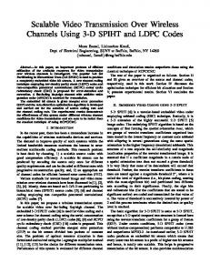
(a) Architecture
(b) Communication
Fig. 1: (a) Cluster architecture showing one possible communication pattern and (b) iWISE-64 with C = 4 and S = 4 showing the wireless communication between sets.
oscillators and filters to distinguish carrier frequencies. Our design reduces the hop count by distributing these transceivers at each router as opposed to a centralized hub found in related work. Packets can avoid multiple hops traveling from the source to a wireless hub and from the wireless hub to the destination. This also distributes the traffic throughout the network by removing the bottleneck caused by a centralized hub to avoid hot spots. At larger cores, the transceivers become slightly less distributed in order to minimize the area overhead which in turn will add slightly more hops from source to hub. However, we utilize single write multiple read (SWMR) communication in order to reduce the hub to destination hop count. In order to share the limited bandwidth, a sharing scheme with tokens is used. We use frequency division multiplexing (FDM) and time division multiplexing (TDM) to avoid interference, and transfer packets among routers on a periodic time frame schedule. The connectivity of our network can reduce the power by about 30% when compared to other wireless/RF networks and improves performance over the Flattened Butterfly (FB) topology and wireless/RF networks with similar bisection bandwidths. The results from our network using real applications such as PARSEC [9], Splash-2 [10], and SPEC2006 [11] show a 1.4 to 2.25 speedup over the FB topology and mesh. The major contributions of this work include: 1) We design hybrid network with distributed wireless hubs that allow for a one-hop 64-core network and a maximum of three-hop 256-core network with traffic distributed to avoid bottlenecks. 2) We propose to reduce global metal wires and additional wireless hubs in a 64-core network and a scalable 256core network by distributing transceivers to all routers and efficiently sharing bandwidth using tokens and SWMR which leads to easier routing.
3) Lastly, we use our sharing scheme to optimize performance, power and area while evaluating our network on synthetic traffic as well as real applications such as PARSEC [9], Splash-2 [10], and SPEC2006 [11] benchmark traces collected from SIMICS [12] and GEMS [13]. II. I WISE A RCHITECTURE In this section we will explain the architecture of iWISE, the routing and flow control used in this design. A. iWISE-64 Design The proposed architecture called iWISE-64 (inter-router Wireless Scalable Express Channel for 64 cores) shown in Figure 1a is defined by the letters (N, C, S, G) where each represent the maximum number of cores per cluster (N), clusters per set (C), sets per group (S), and groups in the architecture (G). The total number of cores in iWISE is the product of N×C×S×G. Figure 1b shows the logical organization of the clusters and sets for iWISE-64. Individual clusters are addressed by the notation C(c, s, g) where c is an arbitrary cluster numbered 0 up to C-1, s is a set numbered 0 up to S-1 and g is a group from 0 up to G-1. In iWISE-64 g = 0 because there is only one group, however, this will change in iWISE-256. In all iWISE architectures we fix N = 4, as concentrating four cores has shown to be an effective technique to reduce the interconnect (router, buffer) area overhead. A wired mesh is used to connect adjacent routers and wireless links are connected between every router. These wireless links are shared such that every set can communicate with every other set including itself. A token-based arbitration scheme is used to fairly allocate clock cycles for a cluster to transmit. Possession of a token represents the right to transmit on a certain frequency to a set. Four tokens are passed between clusters in the same set. 2
Group 2
The tokens are each four bits wide. The index of the set bit indicates the cluster number to which it can transmit. For example, if C(0,0,0) in Figure 1b has the set 1 token then it can send to any cluster in set 1. Since no other cluster in set 0 will have this token, C(0,0,0) will be the only cluster transmitting to set 1. Each set has its own tokens which are independent of other sets. At the receiving set, all four clusters receive the transmitted packet, check to see if the destination matches its own id, then either accepts or discards the packet. For example, when C(0,0,0) transmits to C(1,1,0) in set 1, clusters C(0,1,0), C(1,1,0), C(2,1,0) and C(3,1,0) receive the packet. Cluster C(1,1,0) will then accept the packet while the others discard it. This allows a packet to be sent directly to its destination avoiding the additional hops from a centralized hub to a destination. This may add some power, but the trade-off is reduced latency. A token scheme was chosen because it can be quickly passed around so that a cluster does not have to wait long before it can transmit. Having c = s = 4 gives a set an opportunity for every cluster to transmit to a different set in one time frame since there are four tokens and four clusters. When many clusters want to send to the same set, contention is high and a cluster does not have to wait long to receive a token, so channel utilization is high. However, when contention is low, a cluster can wait as long as 4 clock cycles to receive a token. We call this token sharing scheme Token-Partial (TP). Another alternate design we consider is less restrictive in inter-set communication. Here, we limit ourselves to 16 simultaneous channels and associate one token per channel per destination cluster. This token is shared among all clusters within the network. The cluster that has the token has the right to transmit to the destination. We call this token sharing as Token-Full (TF). Using this approach, communication is not restricted at all, however, a cluster may wait up to 16 clock cycles to receive a token. While this approach may incur additional latency waiting for the token, multiple clusters within a set can simultaneously communicate with multiple clusters in the destination set. This approach can provide improved throughput for certain adversarial traffic patterns. For the router design of iWISE-64, there are four inputs/outputs for the cores, four more for the wired links, and four inputs/outputs for the wireless links. The four receivers are needed so that four sets can simultaneously communicate with one cluster. There are also four transmitters with each representing a set. Each router has four virtual channels (VCs) for each input used to avoid deadlocks. In order to keep track of input buffer allocation, a credit scheme is used. When a flit leaves an output buffer, it decrements the credit count for the destination router. When a flit then leaves this downstream router, a credit needs to be sent back to the upstream router. Since only one bit is needed to send a credit back, this information is piggybacked with packet data.
Wired Link
Group 3
*
*
*
*
*
*
*
*
*
*
*
*
*
*
Set wireless links
Group wireless links
Set Routers Set 2
* * * *
Group Routers
Set 3
*
*
Set 0
Set 1
Group 0
Group 1
Fig. 2: Scalable architecture for iWISE-256 showing the wireless communication between sets where C = 4, S = 4, and G = 4.
this paper. For example, iWISE-256 consists of 256 cores and is composed of four iWISE-64’s where each is a new group as shown in Figure 2. In iWISE-256, the third coordinate g is used to represent which group a cluster belongs. As iWISE scales further, more coordinates can be added to represent higher level logical organizations. iWISE-256 changes slightly to account for the increasing number of routers. First, routers with an asterisk in Figure 2 are now used to communicate with other groups and are called group routers. Group routers are placed such that the traffic load leaving the group is more evenly distributed as opposed to one central group router since in most traffic patterns the majority of the packets will want to take a wireless link. Second, the wireless link that was used to communicate to its own set in iWISE-64 has been removed to save bandwidth and has been replaced with a wired link. This link connects the group router to the opposite corner so that each router is a maximum of one hop away from a wireless link. As a majority of the nodes lie outside the group, in most traffic patterns packets will need to leave the group. Therefore, being only one hop away from the group transceiver will lower packet latency and power dissipation. In iWISE-256, the token scheme is similar to iWISE-64, however for every set there are three “set” tokens to transmit to other sets and three “group” tokens used to transmit to other groups. This means that group routers cannot transmit to set routers and vice versa. Therefore, inter-group wireless communication will require a packet to move to a group router, take a wireless link, then move from another group router to the destination. For example, consider the inter-group communication of C(0,0,0) transmitting to C(1,0,1) in Figure 3. The packet will move in the +y direction from C(0,0,0) to the group router at C(2,0,0). Then it will wait for a “group” token to transmit to the group router at C(2,0,1). Finally, it will move on the diagonal link, or z-direction to C(1,0,1). Likewise, intra-group wireless communication will require a
B. iWISE-256 Design To scale iWISE, the iWISE-64 architecture is repeated G times where G is the number of groups and is equal to 4 in 3
Wired Inputs
*
*
C(2,2, 1)
*
C(3,2, 1)
*
+x -x +y -y z
+x -x
+y -y “Set” 12x12 Crossbar
Wireless Set 0 Inputs Set 1
C(2,0, 0)
*
C(0,0, 0)
+y +x +z
C(3,0, 0)
*
C(1,0, 0)
C(0,2, 1)
C(2,0, 1)
C(3,0, 1)
*
C(0,0, 1)
Inter-Group Communication Path
C(1,0, 1)
Set 3
Cores
C(2,1, 1)
*
C(0,1, 1)
C(3,1, 1)
Wired Inputs C(1,1, 1)
+x -x +y -y z
Cores
Fig. 3: Partial view of iWISE-256 with an inter-group and intra-group communication example.
-x
*
-y
G2
*
+x -y
S1
S0
+x -x +y
“Group” 12x12 Crossbar
S3
z +y
Wireless Outputs
Cores
Group 1 Wireless Group 2 Inputs Group 3
Intra-Group Communication Path
*
z Set 0 Set 1
Set 3 C(1,2, 1)
G3
Wired Outputs
+y
-x
* +x -y
G1
z
Wired Outputs
z Group 1
Group 2 Group 3
Cores
Wireless Outputs S0 = Set 0 G1 = Group 1
Fig. 4: iWISE-256 router design for set and group routers.
packet to move to a set router, take a wireless link, and then move from a set router to the destination. For example, the communication path from C(2,1,1) to C(2,2,1) will first move in the -x direction first to the set router C(3,0,1). The packet will then be wirelessly transmitted to set 2 where C(0,2,1) will accept it. Finally, it will move in the +y direction to the destination C(2,2,1). Packet routing uses the source and destination information to take the shortest path based on the hop count which is a maximum of three in iWISE-256. Wires may be used for inter- and intra-set/group communication with dimension ordered routing. The router architecture for iWISE-256 is shown in Figure 4. The design is similar to iWISE-64, however, only three wireless inputs and outputs are needed for each router and the z direction is added for the diagonal link. Group routers have three transmitters for communication to different groups and similarly for set routers. Sets or groups do not communicate with themselves, therefore one less transceiver is needed reducing the area overhead. To optimize iWISE-64 for area, two separate crossbars can be used. An input crossbar can be used to direct traffic from the incoming wires and wireless receivers to the four cores in each cluster. The output crossbar directs traffic from the four cores to the outgoing wires and wireless transmitters. Since iWISE-64 is a one hop network, all traffic coming into the router from an x or y direction will go to a core and all data leaving the router will come from one of the four cores. Since the crossbar area increases quadratically with the number of inputs/outputs using two separate, smaller crossbars will greatly reduce the area overhead.
total of 16 distinct wireless links, comprising a total system bandwidth of approximately W = 512 Gbps [7]. As shown in Figure 5 using three transmitter and receiver pairs per link each transmitting ∼10.7 Gbps we can achieve our link bandwidth, Bc . In the transceiver blocks, local oscillators are used to generate the different carrier frequencies to which the data is modulated/demodulated. Power amplifiers (PA) and lownoise amplifiers (LNA) are used to amplify the incoming and outgoing signals. Finally, impedance matching and filtering is used to transmit/receive the correct frequencies. The wireless transceivers use on-off keying (OOK) as the simplicity of this non-coherent modulation technique leads to a very low power consumption as well as ultra-compact architecture. There are a few challenges in designing the OOK transceiver for iWISE: common OOK circuitry have been developed for low data rate (