Topic related to an impeller - diffuser hydraulic interaction is important ... the change of the impeller - axial diffuser interaction on quantitative courses of specific.
Interaction between Impeller and Axial Diffuser of Mixed Flow Pump Michal Varchola- Peter Hlbočan Abstract Topic related to an impeller - diffuser hydraulic interaction is important especially in term of energy transformation and performance parameters. A connection of particular functional parts is one of the most important design factors which determine a shape of performance parameters and efficiency. The stated problem is possible to discuss in two possible ways. In term of internal flow pattern and in term of external pump parameters which are represented by performance curve courses. The contribution deals with the influence of the change of the impeller - axial diffuser interaction on quantitative courses of specific energy and efficiency curves.
1 INTRODUCTION One of the most important prerequisites for successful hydraulic design is to manage the interaction between the rotor and stator of hydrodynamic pump. This interaction is formed between geometry of the impeller, diffuser and other hydraulically related elements (inlets, outlets). Geometric interaction is a cause and effect of hydrodynamic properties and efficiency of the pump. The calculation of all the main elements of the pump is generally based on particular algorithms. It is confirmed by multiple experiments that the mutual influence is significant. To sum up, it can be said that the interaction of the impeller and stator substantially affects: internal structure of the flow pump performance parameters effectiveness respectively energy losses in the pump optimal pump parameters (optimum flow rate and specific energy of the pump load on rotor conceptual design of the pump new pump performance characteristics (e.g. vibration, etc.) pump lifetime and reliability regulatory options (operating area, etc.) Quality of hydrodynamic pump on the market is assessed according to price and other performance factors (durability, reliability, materials used, application based on various working fluids, etc.) as well as based on its parameters and special functional properties or capabilities. These properties are achieved by technological, design and/or hydraulic interferences to the "traditional" forms respectively procedures of hydraulic design. The result is an interaction of functional elements with implications on power or hydraulic parameters including specific claims. One of the possible applications of a diagonal pump is conjunction of impeller with an axial diffuser. Such a combination allows the reduction of the dimensions, the use of welded diffuser and thus utilization of difficult to cast materials and overall technological efficiency. However, the application of such a diffuser raises many issues especially related to hydraulic design. 2. DIFFUSER TYPES AND THEIR PROPERTIES
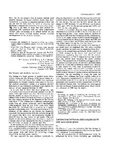
In general, diagonal impeller can be applied in conjunction with spiral (Fig. 1); the section pump with diffuser can be applied with centripetal portion (Fig. 2) or frequently used blade diffuser
according to Fig. 3. The concept of using welded construction of diffuser encourages us to use meridional cut, which is shown in Fig, 4.
Fig. 1 Diffuser – Spiral
Fig. 3 Blade diffuser of single-stage diagonal pump
Fig. 2 Blade diffuser of section diagonal pump
Fig. 4 Axial blade diffuser of diagonal pump
It is known that the spiral pump achieves the highest efficiency. Mixed-flow pump with vane diffuser is strongly influenced by the design concept. An effort to reduce the size and weight of the pump leads to reducing the outer diameter of the pump (diffuser). This paper deals with the influence of some geometrical parameters on the performance and effectiveness of diagonal pump.
3. INFLUENCE OF DIFFUSER SIZE ON OPTIMAL POINT OF PUMP Hydraulic interaction of impeller and diffuser are resulting in the final performance parameters of the pump. On the one hand, impeller and diffuser are proposed using the calculation parameters; on the other hand, real parameters of the pump are influenced primarily by the hydraulic interaction. The consequence is that the resulting pump parameters are often different from the calculation parameters of the impeller and diffuser. In terms of their absolute values, they can often be regarded as satisfactory. It can then be concluded that for each impeller is feasible to design a number of diffusers of various sizes; each of the combinations of impeller - diffuser will form a separate pump, different from the other ones by different values of the optimal parameters, while the absolute values of these parameters are corresponding to real achieved values. The following parameters are interested during the design of the impeller and diffuser: - The required flow rate Q and the specific energy Y in the best efficiency point
- Maximum efficiency and consequent issue of appropriate geometry for the value of efficiency Optimum point of the pump is determined by the flow at which the energy distribution at the inlet to the diffuser is the most balanced. From physical point of view, it represents the minimum losses attributable to the mutual compensation of the uneven distribution of specific energy from input to output. This prerequisite is fulfilled by all points lying on a characteristic of diffuser. Therefore, the operating point of the pump is defined as the intersection of the characteristics of the impeller and diffuser. We get theoretical characterization of the impeller with a finite number of blades when modify known equation for specific energy as follows:
Y Q cot g2
(1)
Correction of the flow from equation (1) is expressed in modified form [6]:
1 2 tg 2 tg1 1
Q tg 2
b2 b1
(2)
We use a correction of specific energy from equation [6]:
Y
1 e 2 / zsin e 2 / zsin
2
3
where
(3)
tg 2 1 tg 2
and is an angle of the main streamline of the impeller radial, o axial). For characteristic spiral shape and the shape of the velocity profile c u .r=const. was equation (4) [2] expressed:
hk hs
r A A2 hk hs s 2 br r2 A 2 r2 dr r
(4)
In equation (4), we use a coefficient for spiral S :
S hk hs
rs A2 r2 A2
(5)
Similarly, an equation with parameter D for blade diffuser was expressed as follows:
y
2
1 h tg 4 2 D r A
A
4
(6)
As already mentioned, the position of the BEP opt , opt is represented by the intersection of two lines - the characteristics of the impeller (1) and the characteristics of the diffuser in the form:
S resp. D
(7)
By solving the equation system (1) and ( 7) we obtain the result for parameters and in the form:
opt
opt
Y
S Q cot g 2
, resp. opt
1 Y S tg 2 1 Q
Y
D Q cot g 2
resp. opt
1 Y D tg 2 1 Q
( 8)
(9)
Thereby it is simply described a hydraulic interaction between impeller and diffuser. At the same time, for the diffuser, the parameters of the pump will likely influence parameters acting in relation (6). The influence of the mentioned parameters is determined by their variation and afterwards we were focused on the values of hydraulic efficiency and transport height obtained by CFD simulation. 4. CFD SIMULATION OF THE FLOW IN THE PUMP
CFD simulation was performed in the calculated area, which included the straight section of the suction pipe, impeller, diffuser and a section of the discharge pipe (Fig. 5). Straight section of the suction pipe must be long enough because of the correct definition of boundary conditions. The reason is that the secondary phenomena at the inlet of the pump tend to be intensive in some cases. It occurs in the regimes with the flow which is smaller than optimal one. In this case, the length of the straight section of the suction pipe is equal to five times the inlet diameter of the impeller. In real conditions, a bend is usually located in the area of the diffuser discharge affecting the final structure of the flow. Therefore, the straight section of the discharge tube is a simplification which may be reflected on the size of the calculated specific energy and hydraulic efficiency. Impeller considered in the CFD simulation was without front shroud (open impeller). We have also calculated the flow in the gaps between the tips of blades of the impeller and the pump body. Computing mesh comprised of about 2.5 million mostly hexahedral elements. A small portion of computing mesh consisted of prism elements. In the areas close to walls as well as in the spaces between the tip of the rotor blade and the pump body a computing mesh was significantly refined. Computing mesh is shown in Fig . 5. Application of the model is time-steady flow. Currently it is preferred an application of an approach of unsteady flow model. In this case, the steady-state flow model was implemented mainly due to the numerous analyzed alternatives of diffusers and thus considerably reduced demand on computation time. The disadvantage of this approach is that the result depends on the relative position of the impeller and diffuser.
Fig. 5 Computing mesh and computing model of the pump The disadvantage of this model is that mainly at non-optimal flow regimes, time-varying interactions between the impeller and the diffuser are not taken into account in the calculation. Interface between the rotor and the stator of computer domain were of the "Frozen Rotor" type. Considered simplifications of the CFD model introduces some errors (uncertainties) into the analysis. We should bear in mind the fact that the analysis is performed as a relative comparison of several alternatives of the diffuser. Thus, when considering that the final error in the results in each case is roughly equal, this approach can be used for this purpose. The simulation uses implemented SST turbulence model and automatic wall function. This model is further characterized in [6]. The model provides significantly better results compared to standard k- ε and k- ω model, particularly in cases that are characteristic of the reverse flow pressure gradients and separation areas. These are characteristic for turbo-machines mainly at non-optimal flow regimes. The inlet total pressure and mass flow at the outlet were applied as boundary conditions. Moreover, rotor revolutions were specified (1850 min-1). Wall of the pump body was specified as oppositely rotating.
Fig. 6 The total pressure and absolute velocity in the area between blades of the pump, the flow-rate Q = 250 l/sec (design point)
5. OBTAINED RESULTS Within solving of the complex issues of interaction of blade diffuser and mixed-flow impeller we are focused mainly on the influence of the diffuser diameter (or y) and its meridian width (b 4). The equation (6) shows that diffuser inlet area to the outlet area of the impeller is an important parameter simultaneously as the parameter y, which means the vertical distance of the impeller to inlet edge of the diffuser in the inlet diameter on the main streamline. Important parameters are also the length of diffuser blades as well as the inlet and outlet angle of the diffuser. The mentioned parameters were the same within this task. For all researched alternatives the parameter x = 82 mm. Calculation parameters were as follows: Q = 250 l/sec, H = 2237 m at revolutions n = 1850 1/min. The overall views on the impeller with different diffusers are shown in Fig . 8. Quantitative change of the width of the diffuser
and the distance y are shown in Tab. 1. Sample of the internal structure of the flow structure is shown in Fig . 6
Fig. 7 Geometric parameters of axial diffuser
Fig. 8 3D view on alternatives of the pump with the axial diffuser according to the Tab. 1
Tab. 1 Quantitative change of parameters of meridian section of the diffuser
Y/b4
Y
b4 y1/b1
y1/b2 y1/b3
y2/b1
y2/b2 y2/b3
y3/b1
y2/b3 y3/b3
Y/b4
Y
b4 10/20 10/40
10/60
40/20 40/40
40/60
70/20 70/40
70/60
Q - ηH
Q-H Head - H [m]
Hydraulic efficiency ηH [%]
The results are shown in Fig. 9 to 13. Fig. 9 to 11 are QH and Q-η characteristics for the first line of Fig. 8 Effect of change of diffuser width is shown on the values of the optimal flow position (Fig. 12) and change of head. Disproportionate increase in the meridional width of the diffuser adversely affects the size of the hydraulic efficiency and transport height. Quantitative impact can be assessed from Fig. 9 to 13.
DIF y1b1 DIF y1b2 DIF y1b3
Flow-rate Q [l / s]
DIF y1b1 DIF y1b2
DIF y1b3
Flow-rate Q [l / s]
Q - ηH
Q-H
DIF y2b1 DIF y2b2 DIF y2b3
Flow-rate Q [l / s]
Head - H [m]
Hydraulic efficiency ηH [%]
Obr. 9 Q-H curve and hydraulic efficiency for alternative with y1= 10 mm
DIF y2b1 DIF y2b2 DIF y2b3
Flow-rate Q [l / s]
Fig. 10 Q-H curve and hydraulic efficiency for alternative with y2= 40 mm
Q - ηH Hydraulic efficiency ηH [%]
Head - H [m]
Q-H
DIF y3b1 DIF y3b2 DIF y3b3
Flow-rate Q [l / s]
DIF y3b1 DIF y3b2 DIF y3b3
Flow-rate Q [l / s]
Fig.11 Q-H curve and hydraulic efficiency for alternative with y3= 70 mm Vplyv vstupnej plochy na Qopt y=10 mm
y=40 mm
Qopt [ l/s]
y=70 mm
A2/A4 [ - ] Fig.12 Influence of diffuser area and diameter D4 on optimal flow
Vplyv vstupnej plochy na účinnosť y1=10 mm
y2=40 mm
h [ %]
y3=70 mm
A2/A4 [ - ] Fig.13 Influence of diffuser area and diameter D4 on hydraulic efficiency
6 CONCLUSION The results of CFD simulation of the same impeller with diffusers of various shapes in meridional cut, i.e. varying the width and the distance y (see Figure 7 and 8), are as follows: -
Shape of meridional cut affects the optimal position of the pump flow. In particular, the ratio A2/A4 (output surface of the impeller and diffuser inlet area) affects the efficiency as well as the optimal flow.
-
The most preferred ratio A2/A4 is in the range of 1 to 1.5.
-
Expanding the meridional cut of diffuser (b4) adversely affects the value of the hydraulic efficiency and thus the head reached.
-
By changing the geometry b4 and y, the position of the optimal flow rate ranged from 200 to 320 l/sec. BIBLIOGRAPHY
[1] GÜLICH, J.F.: Centrifugal Pumps, Springer Berlin, Heidelberg, New York, 2000 [2] STRÝČEK, O.: Hydrodynamické čerpadlá, 2.Vydanie, Vydavateľstvo STU, Bratislava 1992 [3] MENTER, F. R., KUNTZ , M. , LANGTRY , R.: Ten Years of Industrial Experience with the SST Turbulence Model, Otterfing Germany, 2004 [4] VARCHOLA , M.: K otázke hydraulického riešenia špirály hydrodynamického čerpadla Strojnícky časopis 1996 č.2 str 84-93. [5] VARCHOLA , M., HLBOČAN, P.:Prime geometry solution of e centrifugal impeller within 3D setting. In: MARCINKOVSKIJ, V. -- TVERDOCHLEB, I. -- SAVČENKO, E. Teorija i praktika nasoso i kompressorostroenija : monografija. Sumy: Sumskij gosudarstvennyj universitet, 2011, s. 170--176. ISBN 978-966-657-384-4. [6] HLBOČAN, P., VARCHOLA , M.:Vplyv počtu lopatiek diagonálneho čerpadla na jeho charakteristiky. In: AEaNMiFMaE 2012, ŽU Žilina [7] VARCHOLA , M., KNÍŽAT, B: The relation between pump parameters and the spiral casing size, Pump Congress Karlsruhe 1996, Section C7, Preprint P/C 7-4. [8] VARCHOLA ,,M. ,GOLHA,M. :Hydraulický návrh čerpadla vo vzťahu k interakcii obežného kolesa a difúzora. In.: Acta Mechanica Slovaca 2002 str.455-462 [9] VARGHESE G. – MOHANA KUMAR T.C. - RAO Y.V.N.: Influence Volute of surface roughness on the Performance of a Centrifugal Pump, Journal of Fluid Engineering N12 1978 Vol.100 (pp 473-476). [10] HERGT P.: The Influence of the Volute Casing on the Position of the Best Efficiency Point, 11th IAHR Symposium, Amsterdam 1982, Vol.3 [11] VARCHOLA , M., HLBOČAN, P.: Hydraulická väzba obežného kolesa a axiálneho difúzora diagonálneho čerpadla, 145 rokov SIGMA Lutín, Lutín 2013