Al~traet. Matrix cracking and edge delamination are two main damage modes in continuous-fibre composite lamin- ates. They are often investigated separately, ...
~ S ' -
Composites Science and Technology 50 (1994) 469-478
;~ ~ , , ~ .
~ ? ' .
. ~ ~
,-
r3 ~a:i-.;~
INTERACTION B E T W E E N M A T R I X C R A C K I N G A N D E D G E D E L A M I N A T I O N IN COMPOSITE L A M I N A T E S Luo-Yu Xu* Structural Strength Division, Research Institute for Special Structure of Aeronautical Composites, PO Box 302, Jinan, Shandong Province 250023, Peoples Republic of China (Received 18 January 1993; revised version received 20 May 1993; accepted 1 July 1993) Al~traet Matrix cracking and edge delamination are two main damage modes in continuous-fibre composite laminates. They are often investigated separately, and so the interaction between two damage modes has not yet been revealed. In this paper, a simple parallel-spring model is introduced to model the longitudinal stiffness reduction due to matrix cracking and edge delamination together. The energy release rate of edge delamination eliminating the matrix crack effect and the energy release rate of matrix cracking in the presence of edge delamination are then obtained. Experimental materials include carbon- and glass-fibre-reinforced bismaleimide composite laminates under static tension. The growth of matrix cracks and edge delaminations was recorded by means of N D T techniques. Results show that matrix cracks may initiate before or after edge delamination. This depends on the laminate layup, and especially on the thickness of the 90 ° plies. Edge delamination may also induce matrix cracking. Matrix cracking has a significant effect on the stiffness reduction in GRP laminates. The present model can predict the stiffness reduction in a laminate containing both matrix cracks and edge delaminations. The mixedmode delamination fracture toughness obtained from the present model shows up to 50% differences compared with O'Brien's model for GRP laminates. However, matrix cracking has a small effect on the mixed-mode interlaminar fracture toughness of the CFRP laminates.
modes in continuous-fibre composite laminates, and they have been studied widely. ~-28 However, these two types of damage were often studied separately by researchers according to their personal interests. Generally, the researcher who is interested in matrix cracking pays little attention to the delamination problem, while the researcher investigating delamination often ignores matrix cracking effects. Thus, the interaction between matrix cracking and delamination has not been clearly elucidated. Only in recent years have Allen et al. and Talreja employed a continuous damage mechanics method to study the laminate stiffness reduction caused by matrix cracking and delamination together, 29"~ but they did not concern themselves with interactions between matrix cracking and delamination. In practice, both matrix cracking and delamination often occur in damaged laminates under fatigue or impact loadings, etc, and they often intersect perpendicularly. Becaus~ of the complexity of modelling of a laminate containing matrix cracking and delamination together, an exact analytical solution is difficult to establish. Edge delamination testing is now often used to measure the mixed-mode interlaminar fracture toughness, and typical approximate analytical models such as O'Brien's model are used to characterize the edge delamination. 9"~°'~4-16 However, matrix cracking in the 90° plies is still an obscure problem which may lead to significant error in prediction of stiffness reduction and fracture toughness of a glass-fibre composite laminate. ~4'17 Hence, the objective of the present investigation is to build an approximate stiffness-based model to study the preliminary results of interaction between edge delamination and matrix cracking.
Keywords: composite laminate, matrix cracking, edge delamination, interaction, stiffness reduction 1 INTRODUCTION Intralaminar cracking (matrix cracking) and interlaminar cracking (delamination) are the two main damage
2 MODELLING
* Present address: R&D Division, Si-Da Technology Development Centre, Jinan Branch, No. 113 JieFang Lu, Jinan, Shandong Province 250013, China.
2.1 Matrix cracking and stiffness reduction in a symmetric balanced laminate The first problem in studying the interaction between matrix cracking and edge delamination is the modelling of stiffness reduction caused by matrix
Composites Science and Technology 0266-3538/94/$07.00 I~) 1994 Elsevier Science Limited. 469
Luo-Yu Xu
470
cracking in symmetric balanced laminates. Because transverse matrix cracking is easy to induce in a cross-ply laminate, many researchers are interested only in modelling the matrix cracking problem in cross-ply laminates. 2'~8-23 Few experimental results and analytical models have been presented of studies of matrix crack growth and stiffness reduction in a symmetric balanced laminate which has uncracked orthotropic balanced sublaminates such as [+45/0/90]s, [+302/90/9~]s, etc. 14.24-26,29.3o However, there are many matrix cracks in these laminates before edge delamination initiation. Although some models have been established to deal with matrix crack growth and stiffness reduction, few experimental results have been compared to verify these models. 25"26"29'3°The matrix crack growth is associated not only with the cracking stress state but also with the distribution of initial defects, so the analytical model cannot predict matrix crack growth well and a probabilistic method should be employed, xg'z3,27 Hence, the stiffness reduction caused by matrix cracks rather than matrix crack growth will be mainly studied in this paper, as the stiffness reduction is a global parameter which depends on the total matrix crack effect only, and it can be predicted well by analytical m o d e l s . 2"14"19-22 Tan and Nuismer develope~t a so-called 'approximate two-dimensional elastic theory' to deal with matrix cracking in the central 90 ° plies of a symmetric balanced laminate. Because transverse matrix cracking in 90 ° plies does not lead to a change in the orthotropy of the laminate response, the longitudinal Young's modulus can be described by the constitutive relation of the damaged laminate: 26
Exq) = A,~(t) A~'2(~) A22(l)
(1)
where the parameters fi'~i, i, j = 1, 2 are the laminate sitffnesses given in the following:
h('~Q~ ~+ h~2~Q~2~~ .zi,, (l) =
f12/~
(2)
/~ /.~(1)/~1(1) -[- t'4 /~(2)[q1(2)
AI~(I)_~,~,, e~2 fl~~,2,, el2 h (l)t'~(I) d- htZ)Q(2~)
.zi~2(l) =
~22 /~
(f12 - fll~ ,,/~(1)t°(1)2~12 \
/32
/
/~Q]])
(3) (4)
The superscripts (1) and (2) denote sublaminate 1, the 90 ° plies with matrix cracks, and sublaminate 2, the uncracked orthotropic effective constraining plies. Q~), i, j = 1, 2, 6 are the sublaminate stiffnesses along the laminate axes; h i is the thickness of the sublaminate; and/~ is the half-laminate thickness. The parameter/3t and/32 are: tanh o:1l /3, = 1 c~,l (5)
(htl)Q~])] tanh a',l f12 = 1 + \htZ)Q]] U
3c,~,)~'~z) ~55 ~55 ~--
a.,l
(6)
[h~t)Q~ + h~Q~]~
n1.(1)~(2) ~5~ + , ~, ( 2 ) ~~5~ (I) ~ . u(O~O)u(2)~(2) ,, ~ 1 1 " ~11
]
(7)
where r(~) ~ 5 5 , i = 1, 2 are the interlaminar shear moduli of the sublaminate i; 2l is the matrix crack spacing; and matrix crack density D = 1/21. Hahn et al. extended their model to obtain the stiffness reduction due to matrix cracking in a symmetric balanced laminate by using the effective moduli of the orthotropic sublaminate E~,, i = 1, 2. Sublaminates 1 and 2 refer to the ~ o plies and the uncracked constraining plies. The normalized longitudinal Young's modulus of the laminate with matrix cracks is: 24"25
~(o)e~ ~
.(1 + e~t,2Oe~xt~ _ (a + ~)6~(~t~ ~ ~
{ ] ) ~ -' + ~xt,) ~
E~El,tztl
(9)
where t~ is the thickness of the sublaminate, and t is the laminate thickness. In order to simplify the model prediction of stiffness reduction, another method is also proposed by using different expressions for the effective moduli of the untracked orthotropic sublaminate and the cracked 90 ~ plies:
Ex(D)
(1 +E]xt~2D"
=_
.[ K ~-~
where K is the shear-lag constant: ~
K2 = (~ + 1)G2~(E~t2 + E]~t,) s ~ ~ E ~ E ~t2t i
(11)
This means that the effective moduli of the uncracked orthotropic sublaminate and the cracked 90 ° plies, E~,, are replaced by the symmetric sublaminate moduli obtained directly from the classical laminate theory, E~. The value of ~ is set to 2 in Hahn et al.'s model, but we find that if ~ = 1-1, eqns (10) and (11) can predict the stiffness reduction due to matrix cracking in many cross-ply laminates with different materials and layups very well a2 and, hence, we try to use this result in the latter prediction on stiffness reduction in a symmetric balanced laminate.
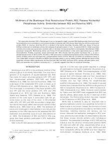
2.2 Stiffness reduction due to matrix cracking and edge delamination Consider a laminate containing matrix cracks and edge delaminations loaded in static tension in the laminate principle X axis as shown in Fig. 1. The Y and Z axes refer to the width and thickness directions of the laminate, respectively. The residual stress effect is not considered here because our purpose is only to highlight the preliminary interaction between matrix
Interaction between matrix cracking and edge delamination
(a)
(b)
Fig. 1. Matrix cracking and edge delamination in a composite laminate. cracking and edge delamination. In order to investigate interlaminar stress and edge delamination, a plane strain model in the X direction is generally employed while studying the matrix cracking problem, and a generalized plane strain (or stress) model in the Y direction is often u s e d . 7'8"18'19'22'26 Thus, we cannot use these assumptions to study a laminate containing matrix cracks and edge delamination together, since this is a real three-dimensional problem. Fortunately, our interest in this paper is not the stress distribution, which is a local parameter and needs a precise analytical method. Another approximate method which can be used to characterize the stiffness of the damaged laminate is to obtain the longitudinal Young's modulus expression by using the approximate deformation feature. Certainly, both methods should be compared with experimental data to verify their validity. The former method employs the general continuous mechanics theory and deals with a specific problem by using certain assumptions and simplifications to obtain the final results from logical principles, a kind of deductive method. The latter method is based on experimental observations to obtain approximate results, a kind of inductive method. A damaged laminate is shown in Fig. 1. Features in Fig. l(a) are often obtained from X-ray radiography. In an ideal case, edge delamination should have a uniform size at the edge without any grip effect of the test machine, as shown in Fig. l(b). Thus, the
471
damaged laminate can be divided into three parts, one part located in the centre of the laminate with only matrix cracks, and the other two parts located at the edges of the specimen with delaminated sublaminates. From a large number of experimental observations on the response of a laminate with matrix cracks, it seems that the stress and strain of a laminate with matrix cracks generally exhibit a linear relationship. The plastic zone caused by matrix cracking or edge delamination is small for the thermoset matrix composites used in our study, so that the linear elastic fracture mechanics (LEFM) is still valid for the characterization of a damaged laminate with edge delamination and matrix cracking. The damaged laminate can be treated as three separate linear elastic components with the same longitudinal strain in what is called a parallel-spring model. This model is limited to the characterization of longitudinal properties and is not valid for transverse properties such as the Poisson's ratio of the damaged laminate. According to the total effective longitudinal equilibrium condition of the laminate and the linear stress/strain relationship, we have:
Ex(a, O)e2b = E'~x(D)eal + Ex(O)e(2b - a~ - a2) + EL(O)eaz
(12)
where Ex(a, D) is the longitudinal Young's modulus of a laminate containing matrix cracks and delaminations together; e is the average laminate strain; E*~(D) is the longitudinal Young's modulus of the completely delaminated laminate and is given by the rule of mixtures; Ex(D) is the stiffness of the sublaminate located in the laminate centre containing only matrix cracks and may be derived from the analytical models described in Section 2.1; D is the matrix crack density; a; is the delamination size; and b is the half-laminate width. Generally, the delamination size of each side is approximately the same, i.e. a~ = a z = a ; then, the in-situ longitudinal Young's modulus of the laminate with matrix crack and edge delamination together can be written in a unified equation: a
E,~(a, D) = (E*~(D) - E,~(D)) -~+ E,~(D)
(13)
The difficulty is the prediction of E*~(D). O'Brien employed the assumption of the two delamination interfaces beside the 90 ° plies and the undamaged separated 90 ° plies for the symmetric balanced laminate. 9"1° In fact, edge delamination jumps from one interface to another and passes through the 90° plies with transverse matrix cracks, so one delamination interface assumption is also introduced. 28 However, the difficulty comes from the complexity of the expression for the longitudinal Young's modulus of the unsymmetric orthotropic sublaminate with matrix cracks, for instance a [:t:45/0/902]v laminate with
Luo- Yu Xu
472
matrix cracks in the 90° plies. In order to simplify the problem, we employ the assumption of two delamination interfaces and introduce our recent result on matrix cracking the low normalized stiffness boundary of the 90° plies with matrix crack (the low boundary value is approximately 0.3) 32 instead of O'Brien's expression in the latter computation. 2.3 Energy release rate characterization According to linear elastic fracture mechanics, 33'34 the basic energy balance relationship during crack growth (both intralaminar-crack/matrix-crack and interlaminar-crack/delamination) under quasi-static tension is: d(U - F + W) = 0 (14) where U is the strain energy of the damaged laminate; F is the work done by the external force; and W is the energy for crack formation (both matrix crack and edge delamination). If the crack is assumed to extend at constant strain, 9"33 the work term in eqn (14) vanishes. Then, from LEFM principles and the observed linear strain/stress relationship, the strain/ energy term can be expressed as a product of the strain energy density and the volume of the laminate, V, so eqn (14) yields:
Thus, we learn that an interaction relationship exists between matrix cracking and edge delamination in the damaged laminate, and its magnitude will be explored in relation to the experimental results.
3 EXPERIMENTS 3.1 Materials and specimens Two kinds of material system were tested. They were T300/QY8911 carbon-fibre-reinforced bismaleimide (BMI) composites and $2/QY8911 glass-fibrereinforced BMI composites. The unidirectional ply properties of the CFRP and GRP systems are given in Table 1. Edge delamination test (EDT) specimens were cut as rectangular coupons from multidirectional panels -whose layups were [+45/0/90]s, [+30z/90]s, [+302/90/90]s and their dimensions of 284 mm length and 25-4 mm width were recommended by NASA for the mixed-mode interlaminar fracture toughness test. 9'~° Woven GRP tabs were bonded on to the ends of the EDT specimens. C-scanning and X-ray radiography were employed to check the defects in specimens before testing.
,~
GddAd+G,~dA,~= - d U = - v e ' t d E x 2
(15)
where Ad, A,. are the crack surface areas of edge delaminations and matrix cracks, respectively; Gd, Gm are the energy release rates for edge delamination and matrix cracking, respectively; V = 2bLt; Ad = 2La; A,, = 4bLDtgo; L is the specimen length; and: dE. = - ~ a da +
0
dD
(16)
By combining eqns (16) and (13) and substituting the result into eqn (15), the energy release rate for a pure edge delamination is obtained: E2I
Gd = - ~ (Ex(D) - E*~(D))
(17)
and the energy release rate for matrix cracking in the 90° plies in the presence of edge delamination is given by: e2t [ dE~*(O) , dEx(O)] G,,, = 4btg~, [a d~--~ + (b - a) - ~ - ~ j (18)
3.2 Test procedure Tests were carried out in an MTS 880 machine under displacement control at a cross-head displacement rate of 1 mm/min. An MTS extensometer with 100mm gauge length was used to measure the strain of the specimen. Specimens were step loaded and unloaded to obtain the detail load/deformation curves recorded in the attached X / Y plotter of the test machine. Edge replication and X-radiography were used to monitor the growth of matrix cracks and edge delaminations. As an additional method, a high intensity light was shone through the GRP specimens to observe in-situ edge delamination and matrix cracks simultaneously. It was found that the stress/strain curves for the GRP specimens had slight non-linearity so the damaged laminate stiffness was given the value of the average tangent stiffness close to the origin. As soon as a delamination was initiated, the specimen was unloaded to record the laminate stiffness because this value is proposed to be used in the new data-reduction method for mixed-mode fracture toughness delamination to eliminate the influence of matrix cracks.
Table 1. Unidirectional ply properties of the test materials Material
E~I (GPa)
E22 (GPa)
G~2 (GPa)
Ylz
tc (mm)
T300/QY8911 (carbon/bismaleimide) $2/QY8911 (glass/bismaleimide)
135.0
8.8
4.47
0"33 0.12
42.8
16-0
4.5
0.31
0.152
Interaction between matrix cracking and edge delamination 4 RESULTS AND DISCUSSION
2.5
4.1 Relationship between matrix cracking and edge delamination From many experimental studies, the dominant damage mode in a cross-ply laminate under static tension is found to be matrix cracking, and the cross-ply laminate shows matrix cracking and matrix crack-tip delamination when under fatigue loading. L2'13 For the symmetric balanced laminate, on the other hand, matrix cracking may initiate before edge delamination, or it may follow the onset of delamination, n As shown in Fig. 2, experimental observations indicate that for the carbon/BMI [+302/90]s laminate, no matrix cracking occurs, so there is no 'knee point' in the stress/strain curve before edge delamination onset. Only after the delamination has grown, as seen from the X-ray photo, do some matrix cracks appear in the delaminated edge zone, but not in the central zone of the laminate_ without delamination. For the glass/BMI [+302/90/90]s laminate, as shown in Fig. 3, the matrix crack density is about 1.5/mm when delamination initiates, and the crack density then tends to the saturation value with the growth of the edge delamination, as shown in Fig. 4. Figure 5 presents the growth processes of matrix cracking and edge delamination in the glass/BMI [+45/0/90]s laminate for which similar results have been found. Hence, matrix cracks may initiate before edge delamination or follow the onset of delamination, depending on the constraining effect of the uncracked
.~ ~
-
0.8
2.0
0.6 .~
~E
~I.B 0.4 ~ r-
.~
'~. ~
'~ :~
F i g . 4.
0.2 "~
0.5
0
0
50 100 150 200 250 300 350 400 Applied stress (MPa)
Growth of matrix cracks and edge delaminations with applied stress; glass/BMI [±302/90~..~]s.
- -
800 [ carbon/BMI [±302/90/~3021T 700
473
2.5
• 2.0t ~E
0.o
/
"~E _~~ 1.5 /[ ~
'~ ~ ~ ~ 0.
/ ~//
~
./"
~ •
= 0.4 .~
•
_
~
~
oo
~
02 ~
o'
Applied stress (~Pa)
Fig. 5. Growth of matrix cracks and edge delaminations with applied stress; glass/BMI [+45/0/90]s. plies and the properties of the 90° plies. This result can be explained by the analytical models described in Section 2.1. From eqn (11) we know that the shear-lag parameter which determines matrix crack growth is an inverse function of the thickness of the 90° plies. In the [+302/90]s laminate, the smaller thickness of the 90° plies leads to a larger shear-lag parameter, which results in a larger cracking strain which may be bigger than the delamination onset strain. There is therefore no matrix cracking in a [+302/90]s laminate before edge delamination onset. After delamination onset, in a delaminated zone of the laminate, the 90° plies lose one side of the constraining effect of the adjacent plies. They are therefore easy to deform and matrix cracking is easy to induce. - -
~ 400 ~ 300
~ 200 100 0
0
0.4
0.8
1.2 1.6 Strain
2.0
2.4
Fig, 2. Experimental stress/strain curves of laminates with matrix cracks and edge delaminations.
2.4 ~~= 2.2 ~ ~2.o
x~16 ~ , ~ 1.4 't-
(,J
•
,
12o
~
.
:
Material $2/QY8911 glass/BMI Layup: [±302/901.5] S
' o'.2
0:4
Normalizod delamination size
~g. 3. Matrix crack growth with the extension of edge delamination.
4.2 Stiffness reduction in a symmetric balanced laminate Generally, before edge delamination initiates there are some matrix cracks in a symmetric balanced laminate. The first stage of laminate stiffness reduction therefore results from the contribution of matrix cracks in the laminate. Figures 6 and 7 show the experimental results for matrix cracking and stiffness reduction and the predictions from the three different methods described in Section 2.1. Before delamination onset, the stiffness reduction caused by matrix cracking is up to 15% in GRP laminates, and clearly this should not be neglected in the characterization of edge delamination which generally initiates after matrix cracking in the stiffness-based
474
Luo- Yu X u 1.001
.~::~,.~.
~
~
~: 0.900"95 ~
~' " ~ ~
~:
z
Experimental ° -- R.Nuismer's Pred. .- H.Hahn's Pred. ...Present Pred.
0.70 0
'
'
|
~ 0.9
.....
• ~
E
-~ 0.8
~ 0.75
.__N ~ 0.7
E~
•
•
o:2
Normalized delamination size
Fig. 9. Predicted and measured stiffness reduction due to matrix cracking and edge delamination; glass/BMI [±45/0/90]~.
~
1 0.95
0.~
•
•
O 0
0B5
0.4 0.8 1.2 1.6 2.0 2.4 Matrix crack density, cracks / m m
• Experimental - - Present Pred. Pred. - ~ •
~
.~t
o.~ 0.75
O
z 0.6
~
o
w x
• Experimental -- R.Nuismer's Pred. ,- H.Hahn's Pred. ... Present Pred.
~
~o 0.70
°x
|•
~
•
--
' 2'.0 ' 2'.4
~.'c:~'~""
~
el
.~ 0.80
Matrix crack density, cracks / mm
Fig. 6. Predicted and measured stiffness reduction due to matrix cracking; glass/BMI [-1-45/0/90]s.
~
. . . . . . .
"I~
;•
'
--
~ ¢ 0.90 ~ 0"851 . ~ ~ . O ' B r i e n ' s
fi 0.85 -o ~ 0,80 •-~ E 0.75
1.00 - -
u~ 0.95
0.7 0
--Present Pred. - O'Bden's Pred. ' 0.1
0.2
'' 0.3
~ m a ~ . e ~ Oe~am~m~cn ~ e
Fig. 7. Predicted and measured stiffness reduction due to matrix cracking; glass/BMI [-t-30~/90,.~]s.
model. Other experimental results from Messenger et al. ~7 are also compared with the model predictions shown in Fig. 8. It seems that we cannot say which model is the best one for predicting the stiffness reduction caused by matrix cracks in the symmetric balanced laminate because the results are so close: only the present model is in relatively simple form, however. In later computations the present model is therefore employed because the aim of this paper is only to reveal the magnitude of the effect of interaction between matrix cracks and edge delaminations. In the second stage of stiffness reduction, matrix cracking tends to reach the saturation state (characteristic damage state, CDS). Stiffness reduction caused by edge delamination dominates at this stage, and it can be predicted by the present model by using eqn (13): the results are shown in Figs 9 and 10. However, the
~ 0.9
• •
0~ E
precision of the present prediction is affected by the predictions on the stiffness reduction due to matrix cracking and the modulus of the completely delaminated laminate, E*~(D), for which we have, at present, no better predictive model. Even so, the present model is better than O'Brien's model, especially for the prediction of stiffness reduction in a GRP laminate, because O'Brien ignored the effect of matrix cracking in the laminate. However, for a CFRP laminate, his results are close because matrix cracking causes little stiffness reduction in a CFRP laminate. It is interesting to note that the experimental relationship between stiffness reduction and delamination size retains a linear form which is in good agreement with the prediction of eqn (13). Whitney also obtained the same result by means of a higher-order lamination theory. 8 Thus, our approximate model does not lose its precision by using reasonable approximate assumptions and it is verified by experiment. The whole process of the predicted and measured stiffness reduction is shown in Figs 11 and 12.
• •
.~ o.8 • Experimental -- R.Nuismer's Pred. .- H.Hahn's Pred. " Present Pred.
.N "~ 0.7 O
z 0.6
Fig. 10. Predicted and measured stiffness reduction due to matrix cracking and edge delamination; glass/BMI [+30~/90,.~]~.
0
0.4 0.8 1.2 1.6 Matrix crack density, cracks / mm
Fig. 8. Predicted and measured stiffness reduction duc to matrix cracking; glass/epoxy [+45/0/90]s.
4.3 Mixed-mode fracture toughness characterization and recommended test From the stiffness prediction of the damaged laminate, the mixed-mode energy release rate for the edge delamination can be obtained. Because of the simple test procedure and the large range of the ratio Gn/Gu, the edge delamination test (EDT) is often used to characterize the mixed-mode interlaminar
Interaction between matrix cracking and edge delamination ..~
.,x
3000 • Present method
0.95
475 /
../."
~2ooo ~8 "~ $15oo ~ .~ 1000
~ 0.9 0.85 ~ 0.8 0.75 z 0.7
•
• ~.~oet~mer~:sI ~Predle~Jon 0.4
0~
1.2
1.6
oo
•
2
~ ~ 500
%
2.4
Fig. 11. Predicted and measured stiffness reduction versus applied strain; glass/BMI [+45/0/90]s.
011 012 Normalized delamination size
o13
Fig. 13. Different characterization of the delamination growth-resistance curve; glass/BMI [-1-45/0/90]s. 2000
o~ 1.00 u.~ 0.95
"~= ,~ ~,
~ 0.90 ~=
• Experimental ~- Prediction
~
18oo
• Present method ,ErBrien~
/,
g ~ 1200
"~.'# •
•~: ~
~ 0.85
800
_~'~ ~ ~ 400
~ 0.80' .E 0.75
0.'1 0.'2 0 .~3 Normalized delamination size
O
z 0.70 0
0.4
0.8 1.2 1.6 Applied strain
2.0
2.4
Fig. 12. Predicted and measured stiffness reduction versus applied strain; glass/BMI [+302/90~.s]s.
fracture toughness of a composite laminate. The expression for the mixed-mode fracture toughness from O'Brien's model is: 9"1° e2t
o
Gc = ~ - (Ex - E*~)
(19)
Compared with eqn (17), we find that the main difference between these two equations is that the initial modulus of the undamaged laminate, E~. in eqn (19), is repalced by the in-situ laminate modulus at delamination onset, Ex(D). Since matrix cracking causes a stiffness reduction before the onset of delamination, so E~>~ Ex(D), which means that our result for the mixed-mode interlaminar fracture toughness is generally less than that of O'Brien. For instance, for the mixed-mode fracture toughness of the glass/BMI [+302/90/90]s laminate, up to 20% difference may exist between the results from the present model and those of O'Brien, as shown in Table 2. The difference mainly comes from the
Fig. 14. Different characterization of the delamination growth-resistance curve; glass/BMI [:1:302/901..~]s. contribution of matrix cracking to the fracture energy. ~7 Figures 13 and 14 present the delaminationgrowth resistance curves for the GRP laminates: O'Brien's method gives a sharp increasing curve and the present method gives a stable one. Since such a great difference has been found, the effect of matrix cracking on edge delamination cannot be neglected, especially in GRP laminates. After we have understood the exact meaning of characterization of the mixed-mode fracture toughness of edge delamination, another test method is recommended. Formerly, the modulus of the completely delaminated laminate was computed by the lamination theory and rule of mixtures: it was not measured by experiment, 9 so that, unlike modes I and II fracture toughness characterizations,34 the mixedmode fracture toughness usually obtained is neither a computed parameter nor an experimental value. The reason lies in the obscure meaning of the completely delaminated laminate modulus which should be an experimental value but which is ditficult to obtain from older tests, because the final laminate fracture
Table 2. Comparisons on the mixed-mode inteHaminar fracture toughness
Material and layup O'Brien's method (J/m z) Present method (J/m 2) Difference (%)
T300/QY8911 [+302/90/90]s 273 256 6
T300/QY8911 T300/QY8911 $2/QY8911 $2/QY8911 [+45/0/90]s [+30z/90]s [+302/90/90]s [+45/0/90]s 243 226 7
279 279 0
216 171 21
576 291 50
476
Luo- Yu Xu
~
I
Dolaminallon]
number of fatigue cycles N, we may obtain the stiffness degradation rate:
da dEx(a, D) = (E*~(D) - Ex(D)) b dN dN a OEx(D)] dD + \ b dD+ -
Fig. 15. Recommended mixed-mode interlaminar fracture toughness test. may occur before the edge delamination passes through the whole laminate width. We therefore recommend using the following procedure to measure this value. As soon as delamination occurs, a wedge is employed to force more delamination until the edge delamination passes through the laminate width, as shown in Fig. 15: we may then measure the laminate modulus and use this value in eqn (17).
4.4 Fatigue damage evaluation by the stiffness reduction method Stiffness degradation is often used to evaluate fatigue damage in laminates. 14'3~-3~ Figure 16 shows a typical stiffness degradation curve for a laminate under tension-tension fatigue loading. The observed fatigue damage modes include matrix cracking, delamination, fibre breakage, etc. The stiffness degradation curve is often divided into three stages, as shown in Fig. 16.13 The first stage is a sharp decreasing stage and the second is a linear stage. The stiffness falls very rapidly again and the final fracture occurs in the laminate in the third stage. The stiffness reduction stems from the damage growth, and in each stage a different damage mode plays the major r61e in causing the stiffness reduction. Generally, matrix cracking is the first damage mode to occur in a laminate, and then other damage modes such as matrix crack-tip delamination (local delamination) and edge delamination may occur.13 By differentiating eqn (13) with respect to the
1
(20)
We know that the matrix cracking will tend to a saturation state and the stiffness reduction curve can be described by a hyperbolic function of the form in eqn (11), which agrees with the first statge of the stiffness degradation curve, so the first stage of the stiffness degradation curve is mainly the contribution of matrix cracking. From experimental observations, the edge delamination size is a linear function of the number of fatigue cycles within a wide range of fatigue life and local delamination has little effect on the laminate stiffness reduction. 5"9 From eqn (13), the stiffness reduction should have a linear relationship with the number of fatigue cycles, as shown in Fig. 16, and the experimental results for the second stage are in good agreement with our conclusions. Thus, eqns (13) and (20) build the damage function relationship which may be used in fatigue damage evaluation and life prediction on the basis of practical damage modes.
5 CONCLUSIONS There exists an interaction relationship between matrix cracking and edge delamination. Matrix cracking may lead to local delamination; delamination may induce matrix cracking. According to an approximate deformation feature, the present paper employs a stiffness-based method to investigate the interaction relationship. The longitudinal stiffness reduction due to matrix cracking and edge delamination is well predicted by the proposed parallel-spring model, from which the energy release rate for the pure edge delamination (excluding the effect of matrix cracking) and the energy release rate for matrix cracking in the presence of edge delamination are obtained. Results show that up to 50% difference may exist between the mixed-mode interlaminar fracture toughness results from the present model and those of O'Brien for a GRP laminate. Matrix cracking may initiate before or after edge delamination onset, depending on the laminate layup, especially the thickness of the 90° plies.
ACKNOWLEDGEMENTS 'F~ti~e Li~e
Fig. 16. Schematic representation of the three-stage curve of the stiffness degradation.
The author wishes to thank Profs Bing-Xian Yang and Chang-He Kou at Beijing University of Aeronautics and Astronautics for their assistance during the course
Interaction between matrix cracking and edge delamination of this study. Thanks also go to Mr Wen-Bin Xue for the preparation of the specimens.
REFERENCES 1. Reifsnider, K. L. et al., Damage mechanics and NDE of composite laminates. In Mechanics of Composite Materials, Recent Advance, ed. Z. Hashin & C. T. Herakovich. Pergamon Press, New York, 1982, pp. 399-420. 2. Highsmith, A. L. & Reifsnider, K. L., Stiffnessreduction mechanisms in composite laminates. Damage in Composite Materials, ASTM STP 775, ed. K. L. Reifsnider. American Society of Testing and Materials, Philadelphia, PA, 1982, pp. 103-17. 3. Wang, S. S., Elasticity solutions for a class of composite laminate problems with stress singularites. In Mechanics of Composite Materials, Recent Advance, ed. Z. Hashin & C. T. Herakovich. Pergamon Press, New York, 1982, pp. 259-81. 4. Chan, W. S. & Wang, A. S. D., Effect of a 90° plies on matrix cracks and edge delamination in composite laminates. Comp. Sci. & Tech., 38 (1990) 143-57. 5. O'Brien, T. K., Analysis of local delamination and their influence on composite laminate behavior. In Delamination and Debonding of Materials, ASTM STP 876, ed. W. S. Johnson. American Society of Testing and Materials, Philadelphia, PA, 1985, pp. 282-97. 6. Liu, S. & Nairn, J. A., The formation and propagation of matrix microcracks in cross-ply laminates during static loading. J. Reinforced Plastics & Composites, 11 (1992) 158-78. 7. Armanios, E. A. & Rehfield, L. W., Sublaminate analysis of interlaminar fracture in composites. J. Composite Tech. & Res., 11 (1989) 135-46. 8. Whitney, J. M., Stress analysis of a mode I edge delamination specimen for composite materials. A I A A Journal, 24 (1986) 1163-8. 9. O'Brien, T. K., Characterization of delamination onset and growth in a composite laminate. In Damage in Composite Materials, ASTM STP 775, ed. K. L. Reifsnider. American Society of Testing and Materials, Philadelphia, PA, 1982, pp. 140-57. 10. O'Brien, T. K. et al., Comparisons of various configurations of the edge delamination test for interlaminar fracture toughness. In Toughened Composites, ASTM STP 937, ed. N. J. Johnston. American Society of Testing and Materials, Philadelphia, PA, 1987, pp. 199-221. 11. Crossman, F. W. & Wang, A. S. D., The dependence of transverse cracking and delamination on ply thickness in graphite/epoxy laminates. In Damage in Composite Materials, ASTM STP 775, ed. K. L. Reifsnider. American Society of Testing and Materials, Philadelphia, PA, 1982, pp. 118-39. 12. Wang, A. S. D., Growth mechanisms of transverse cracks and ply delamination in composite laminate. In Proc. 3rd ICCM, Paris, Vol. 1, 1980, pp. 170-83. 13. Reifsnider, K. L., Schulte, K. & Duke, J. C., Long-term fatigue behavior of composite materials. In Long-Term Behavior of Composites, ASTM STP 813, ed. T. K. O'Brien. American Society of Testing and Materials, Philadelphia, PA, 1983, pp. 136-59. 14. Caslini, M., Zanotti, C. & O'Brien, T. K., Study of
477
matrix cracking and delamination in glass/epoxy laminates. J. Composite Tech. & Res., 9 (1987) 121-30. 15. Poursartip, A., The characterization of edge delamination growth in laminates under fatigue loading. In Toughnened Composites, ASTM STP 937, ed. N. J. Johnston. American Society of Testing and Materials, Philadelphia, PA, 1987, pp. 222-41. 16. Johnson, W. S. & Mangalgiri, P. D., Influence of the resin on interlaminar mixed-mode fracture. In Toughened Composites, ASTM STP 937, ed. N. J. Johnston. American Society of Testing and Materials, Philadelphia, PA, 1987, pp. 295-315. 17. Messenger, C. R., Smith, P. A. & Bader, M. G., Effect of resin toughness on delamination growth in composite laminates. In Proc. ICCM 8, Honolulu, SAMPE, 1991, 28-V-1. 18. Hashin, Z., Analysis of stiffness reduction of cracked cross-ply laminates. Engg Fracture Mech., 25 (1986) 771-8. 19. Laws, N. & Dvorak, G. J., Progressive transverse cracking in composite laminates. J. Comp. Mater., 22 (1988) 900-16. 20. Ogin, S. L., Smith, P. A. & Beaumont, P. W. R., Matrix cracking and stiffness reduction during the fatigue of a (0/90)s GFRP laminate. Composite Sci. & Tech., 22 (1985) 23-31. 21. Varna, J. & Berglund, L., Multiple transverse cracking and stiffness reduction in cross-ply laminates. J. Composites Tech. & Res., 13 (1991) 99-106. 22. Lee, J. W. & Daniel, I. M., Progressive transverse crack of crossply composite laminates. J. Composite Mater., 24 (1990) 1225-43. 23. Peters, P. W. M. & Chou, T. W., On the cross-ply cracking in glass and carbon fiber-reinforced epoxy laminates. Composites, 18 (1987) 40-6. 24. Han, Y. M. & Hahn, H. T., Ply cracking and property degradation of symmetric balanced laminates under general in-plane loading. Composite Sci. & Tech., 35 (1989) 377-97. 25. Hahn, H. T., Han, Y. M. & Kim, R. Y., Resistance curves for ply cracking in composite laminates. In Proc. 33rd Int. SAMPE Syrup., 1988, pp. 1101-8. 26. Tan, S. C. & Nuismer, R. J., A theory for progressive matrix cracking in composite laminates. J. Comp. Mater., 23 (1989) 1029-47. 27. Wang, A. S. D., Chou, P. C. & Lei, S. C., A stochastic model for the growth of matrix cracks in composite laminates. J. Comp. Mater., 15 (1984) 239-54. 28. Ye, L., Characterization of delamination resistance in composite laminates. Composites, 20 (1989) 275-81. 29. Allen, D. H., Grove, S. E. & Harris, C. E., A cumulative damage model for continuous fiber composite laminates with matrix cracking and interply delaminations. In Composite Materials: Testing and Design (8th Conf.), ASTM STP 972, ed. J. D. Whitcomb. American Society of Testing and Materials, Philadelphia, PA, 1987, pp. 57-80. 30. Talreja, R., Stiffness properties of composite laminate with matrix cracking and interior delamination. Engg Fracture Mech., 25 (1986) 751-62. 31. Xu, L. Y., Kou, C. H. & Yang, B. X., An analogous investigation on transverse cracking in composite laminate and concrete pavement. In Proc. 8th Int. Conf. on Composite Materials, Honolulu, SAMPE, 1991, 27-F- 1. 32. Xu, L. Y., Exploration on constants independent of material and layup in transverse matrix cracking of
478
Luo- Yu Xu
cross-ply laminate. Advanced Composites Letter, 2 (1993) 25-8. 33. Broek, D., Elementary Engineering Fracture Mechanics, Sijthoff and Noordhoff, Leyden, The Netherlands, 1978. 34. Whitney, J. M., In lnterlaminar Response of Composite Materials, ed. N. J. Pagano. Elsevier Science Publishers B.V., Amesterdam, 1989, pp. 180-239.
35. Wang, S. S. & Chim, E. S.-M., Fatigue damage and degradation in random short-fiber SMC composite. J. Comp. Mater., 17 (1983) 114-34. 36. Spearing, S. P., Beaumont, P. W. R. & Smith, P. A., Fatigue damage mechanics of composite materials Part 4: Prediction of post-fatigue stiffness. Composite Sci. & Tech., 44 (1992) 309-17.