George E. Hilley1, J Ramón Arrowsmith, and Lee Amoroso. Department of Geological Sciences, ... duced [Altunel and Hancock, 1993]. For example, extension.
GEOPHYSICAL RESEARCH LETTERS, VOL. 28, NO. 19, PAGES 3777-3780, OCTOBER 1, 2001
Interaction between normal faults and fractures and fault scarp morphology George E. Hilley1 , J Ram´on Arrowsmith, and Lee Amoroso Department of Geological Sciences, Arizona State University, Tempe, Arizo na
Abstract. Fault slip and geomorphic surface processes create and modify bedrock normal fault scarps. Our field studies and numerical models show that mechanical interaction between near-surface fractures and active faults may diminish scarp slopes and broaden deformation near the surface. In our models, increasing fracture density and depth reduces and complicates the scarp’s topographic expression. Fracture depth and density, and orientation of the structures control the location and magnitude of zones of positive and negative shear displacements along the fractures. Our field studies of the interaction of active graben bounding normal faults and fractures in Northern Arizona illustrate the mechanical analysis. Reduction in scarp slopes and broadening of the deformation field may cause incorrect interpretations of shallow bedrock scarp morphologies as old, rather than as the result of slip along fractures around the fault.
opening along the fractures; the presence of fractures in the near surface results in larger total offset for a constant stress drop than a fault in isolation. To illustrate the mechanical analysis, we studied active fault scarps along low slip rate graben-bounding faults of the southern Colorado Plateau that expose pervasively fractured rocks of the Permian Kaibab Formation and Triassic Moenkopi Formation. Our field observations show irregular topography resulting from distributed deformation along near-surface fractures. Thus, irregular fault scarp morphologies do not require surface transport processes to redistribute material and instead may result from near-surface distributed deformation.
Introduction
We constructed a boundary element model to compute slip and opening along fractures in the vicinity of a slipping fault. The crust was idealized as a homogeneous, linear elastic half-space subject to plane-strain [e.g.; Jaeger and Cook, 1969; Segall and Pollard, 1980; Segall, 1984]. Faults and fractures were modeled by introducing a set of confined frictionless displacement discontinuities in the crust [Segall and Pollard, 1980; Crouch and Starfield, 1983]. We allow the fault to slip in response to a shear stress drop along its downdip length [e.g.; Willemse, 1997; Crider and Pollard, 1998], which results in the loading of the surrounding medium and fractures. The fractures then slip solely in response to this stress transfer. By neglecting the effect of remote stresses along the fractures, we implicitly assume that induced stresses near the fault are large compared to remote stresses. Although friction, lithostatic loading, and the associated Poisson stresses are neglected in our simple model, previous work has shown that first-order features of the stress and deformation fields are captured by this approach [Segall and Pollard, 1980; Willemse, 1997; Thomas, 1993].
Numerous detailed studies of seismically generated fault scarps have resulted in models that determine age of faulting events, rates of movement along faults, and recurrence time between earthquakes from scarp topographic form [e.g.; Nash, 1980; Hanks et al., 1984; Bucknam and Anderson, 1979; Avouac, 1993; Arrowsmith et al., 1996, 1999]. These studies were conducted on regolith mantled scarps; however, scarps within fractured bedrock are common throughout the world and occur at a variety of scales [e.g.; Stewart and Hancock, 1990; Strecker et al., 1990; Cannon and B¨ urgmann, 1999; Villemin et al., 1994]. In such areas, an additional set of complex geomorphic and tectonic processes are introduced [Altunel and Hancock, 1993]. For example, extension may be accommodated by both slip along normal faults and opening of fissures in the area around the fault. In these cases, shallow topographic slopes around fault scarps may be produced and maintained by near-surface structural complexity. We used mechanical models and field observations to investigate how slip along fractures near the earth’s surface leads to distributed surficial deformation and irregular scarp morphologies. We used mechanical models to explore how surface displacements changed with fracture depth, density, dip, and fault dip. Increasing fracture depth and density cause scarp morphology to become more irregular, as interaction between fractures and the fault becomes more important. Fracture orientation controls the sense of shear and 1 Now at Institut f¨ ur Geowissenschaften, Universit¨ at Potsdam, Potsdam, Germany
Copyright 2001 by the American Geophysical Union. Paper number 2001GL012876. 0094-8276/01/2001GL012876$05.00
Fractures in the vicinity of a slipping fault
Models of Interacting Faults and Fractures In our models, we varied fault dip (β), fracture dip (γ), fracture length (λ), and fracture density (1/ξ). The horizontal position, fracture length, and fracture density were normalized by the fault length (L). Therefore, surface displacement at a point is controlled by six variables: stress drop (ts ), normalized position (x/L), β, normalized fracture length (λ/L), γ, and normalized fracture density (L/ξ). We considered a normal fault undergoing an uniform 4.33 MPa stress drop along its length. Elastic parameters typical of rock (i.e., shear modulus of 30 GPa and Poisson’s ratio of 0.25) were used.
3777
3778
HILLEY ET AL.: INTERACTION BETWEEN NORMAL FAULTS AND FRACTURES
(a)
(b)
(c)
-4
4 x 10 0
Elevation (H/L)
-4 -8
no fractures λ/L = 0.025 λ/L = 0.05
-12 -16
(d)
(e)
(f)
-5
4 x 10 0 -4 -8 -12
-0.08
0
0.08
-0.08
0
0.08
-0.08
0
0.08
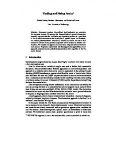
Distance (x/L) Figure 1. Scarp profiles produced by a stress drop along a 60◦ dipping normal fault. (a)–(c) Surface displacements for a fault that reaches the surface. (d)–(f) Displacements for a fault with the upper tip buried 0.1L below the surface. (a) and (d), (b) and (e), and (c) and (f) Displacements resulting from 60◦ , 90◦ , and 120◦ dipping fractures, respectively. The heaviest line shows the case in which fractures are not present, and progressively lighter lines show the case of deeper fractures (0.025L and 0.05L). Fracture density is fixed to 0.01L. H is elevation. Cartoon depicts general fracture and fault geometry relative to surface.
Finally, the effect of normal fault dip was investigated (Figure 2b and d). In all cases, fractures were vertical, extended to a depth of 0.05L, and had a density of L/ξ = 0.4. The fault dip did not greatly influence the sense of motion along the fractures; however, the offset magnitude along the
(a)
(b)
-4
x 10
x 10
-4
0
0
-2 -2
Elevation (H/L)
We first examined the effect of fracture length on surface displacements surrounding the fault scarp. Progressive increase in fracture length relative to fault length increased mechanical interaction of fractures, modifying the surface displacement field (Figure 1). Long fractures slipped more than short fractures, causing scarp morphology to be jagged and slopes to decrease. We found that fracture dip also has an important influence on scarp morphology. In cases where the fault reached the surface (Figure 1a–c), fractures in the footwall dipping at 60◦ slipped only moderately, while those in the hangingwall showed large displacement reverse motion. With a 90◦ dip, both postive and negative shear displacements resulted from movement along the fault. Where the fault did not reach the surface (Figure 1d–f), a stepped flexure resulting from movement along the underlying fault was produced. Fractures dipping parallel to the fault caused reverse shear in the hangingwall and normal shear in the footwall (Figure 1d). When fractures dipped into the fault, reverse motion along the fractures was often resolved. Figure 2a and 2c show the effects of fracture density on surface deformation. Figure 2a demonstrates surface deformation resulting from the interaction of a 60◦ dipping fault that reaches the surface with 90◦ dipping fractures extending to a depth of 0.05L. This set of models shows that mechanical interaction between fractures increases with fracture density, and that complex surface displacement distributions result from increased fracture density. When the fault did not reach the surface (Figure 2c; upper fault tip is buried 0.1L), increased fracture density magnified the steps of the monoclinal flexure. With higher fracture density, total relief across the structure increased while slip on each fracture decreased simultaneously.
no fractures L/ξ = 0.1 L/ξ = 0.05 L/ξ = 0.01
-4
(c) x 10
β = 45o o
β = 60
-4
o
β = 90
-6
(d)
-5
0 -4 -8 -12 -0.08
0
0.08
-0.08
0
0.08
Distance (x/L)
Figure 2. Scarp profiles produced by variations in fracture density and fault geometry. (a) and (c) Effects of changes in fracture density for surface rupturing and blind faults, respectively. (b) and (d) Effects of changes in fault dip for surface rupturing and blind faults, respectively.
HILLEY ET AL.: INTERACTION BETWEEN NORMAL FAULTS AND FRACTURES
(a)
Colorado Plateau
TRm
Tension fissure
TRm Pk
Qya
Arrowhead Graben
Flagstaff
Lineament Scarp
3
Basin and Range
Qyf 2
3779
Bedding strike and dip
5
Monocline
Arizona
Qbb
Fault, ball on downthrown side Fault, approximate location Fault, concealed
A'
3 3
20
Qmb
Pk
6
Qyc, younger alluvium
B'
8
B A
Qya, young alluvium Alluvial fans Qyf, mid alluvium Qyo, oldest alluvium Qbb, mid Pleistocene basalt
Pk
?
Pk
2 TRm
9
8
N
Qmb, lower Pleistocene basalt
TRm
3
TRm
?
500 Meters
TR m, Triassic Moenkopi Formation
Qyo
? Pk, Permian Kaibab Formation
A
Qyc
A' Qyo
25
2
(b) Fracture Orientations 5x vertical exag.
Elevation (m)
0
B
B'
25 20%
10
10
20
n = 169
0
5x vertical exag.
125 Meters
Figure 3. (a) Geologic map and cross-sections of Arrowhead graben illustrating relationships among faults, fractures, and monoclines exemplifying aspects of the preceding mechanical analysis. (b) The dominant NW fracture trend is parallel to the graben strike.
fault and along each of the fractures changed with fault dip. Increasing total offset along the fault was paralleled by offset along surrounding fractures (Figure 2b and d). When the fault reached the surface, fractures in the footwall resolved opening and a left-side-up sense of shear, while fractures in the hangingwall resolved opening and right-side-up sense of shear (Figure 2b). In the case where the fault did not reach the surface (Figure 2d), a right-side-up sense of shear and opening was resolved onto the vertical fractures.
Field observations of fault and fracture interaction We selected the Arrowhead Graben (Wupatki National Monument, ∼ 30 km north of Flagstaff, Arizona) because it provides two different fault and fracture geometries, each with a different associated scarp morphology. Faults in the area driven by NE-SW extension [Zoback and Zoback, 1989] displace Paleozoic, Mesozoic, and Quaternary formations
(Figure 3a). Faults are approximately parallel to extensive NW–SE oriented regional joint systems (Figure 3b). Recent fault movement is demonstrated by offset of 800–1600 ka basalts [Moore and Wolfe, 1987] and mid-Pleistocene (?) alluvial fan deposits. Fault-parallel fissures in the footwall have opened 20 cm to 10 m along preexisting fractures up to 200 meters away from the graben-bounding faults. The NW bounding fault of Arrowhead graben reaches the surface, while the SE fault is mostly blind (Figure 3a). The vertical fractures, and surface rupturing and blind 60◦ normal faults make our field studies equivalent to the models shown in Figure 1b and Figure 1e, respectively. Along the NW fault, extension is accommodated primarily by slip along the main fault, with a smaller component taken up by opening and slip along surrounding fractures in the footwall (Figure 3, Scarp Profile 1). Along the blind fault on the SE side of the graben, small magnitude displacements and tilting between near-surface fractures have created a stepped flexure (Figure 3, Scarp Profile 2).
3780
HILLEY ET AL.: INTERACTION BETWEEN NORMAL FAULTS AND FRACTURES
Excepting the colluvial piles at the base of the bedrock scarps, geomorphic transport processes apparently play a minor role in the scarps’ morphology. Instead, the presence of near-surface fractures corresponds to areas of distributed deformation and diminished scarp slopes. In the case of the surface rupturing fault, our observations and models indicate that the main fault plane accommodates much of the deformation; however, fractures around the fault slip in response to fault movement and broaden the deformation. When the fault is blind, flexure is accommodated mostly by slip along near-surface fractures, resulting in a broader and more complicated deformation field than a fault slipping in the absence of fractures. In both cases, slip along near-surface fractures alters the topographic profile of the bedrock scarps relative to previously modeled regolith scarps.
Discussion and Conclusions When fault scarps are mantled by regolith, geomorphic redistribution of transportable material may be the primary agent of slope reduction. However, when faults expose bedrock, local hillslope surface transport processes are limited by the availability of transportable material [e.g.; Selby, 1993; Arrowsmith et al., 1996]. This occurs when tectonic displacement rates exceed the rate at which material is converted to regolith and the initial thickness of unconsolidated material is small. Recent measurements of the rate at which bedrock is converted to regolith [Heimsath et al., 1998] suggest that exposure of bedrock is the rule in tectonic environments undergoing even moderate uplift [Hilley, 2001]. In these cases, processes that control the morphology of a scarp over time are more numerous and complex than when bedrock is not exposed. Our simple model results suggest that the morphology of bedrock fault scarps with low total displacement may result from surface transport processes and actively failing, deep fractures in bedrock. The limiting of surface transport processes by lack of available transportable material enhances the surface expression of slip along near-surface fractures. We may be tempted to invoke surface transport processes such as mass failure and topple to explain irregular fault scarp topography; however, aspects of these profiles observed in bedrock terrains may also be produced by slip along near-surface fractures. Acknowledgments. This research was supported in part by the NASA Earth Systems Science Fellowship granted to GE Hilley. We thank P Pearthree for pointing out field area to JR Arrowsmith. We thank MR Strecker, JL Lewicki, D Rodgers, and two GRL anonymous reviewers for thorough and constructive reviews of the final manuscript.
References Altunel, E., and P. L. Hancock, Active fissuring and faulting in Quaternary travertines at Pamukkale, western Turkey, Z. Geomorph. N. F. 94, 285-302, 1993. Arrowsmith, J R., D. D. Pollard, and D. D. Rhodes, Hillslope development in areas of active tectonics, J. Geophys. Res., 101, 6255-6275, 1996.
Arrowsmith, J R., D. D. Pollard, and D. D. Rhodes, Correction to “Hillslope development in areas of active tectonics,” J. Geophys. Res., 104 805, 1999. Avouac, J. P., Analysis of scarp profiles: Evaluation of errors in morphologic dating, J. Geophys. Res., 98, 6745-6754, 1993 Bucknam, R. C., and R. E. Anderson, Estimation of fault-scarp ages from a scarp-height-slope-angle relationship Geology 7, 11-14, 1979. Cannon, E. C., and R. Bu¨rgmann, Holocene fault offset rates of the Hilina fault system, Kilauea volcano, Hawaii, in Abstracts with Programs, Geological Socity of America 1999 Annual Meeting 31 302, 1999. Crider, J. G., and D. D. Pollard, Fault linkage: 3D mechanical interaction between overlapping normal faults, J. Geophys. Res., 103, 24,373-24,391, 1998. Crouch, S. L., and A. M. Starfield, Boundary Element Methods in Solid Mechanics 323 pp. George Allen and Unwin, London, England, 1983. Heimsath, A. M., W. E. Dietrich, K. Nishiizumi, and R. C. Finkel, The soil production function and landscape equilibrium, Nature 388, 358-361, 1998. Hanks, T. C., R. C. Bucknam, K. R. Lajoie, and R. E. Wallace, Modification of wave-cut and fault-controlled landforms, J. Geophys. Res., 89, 5771-5790, 1984. Hilley, G. E., Landscape development and fault behavior in tectonically active areas, Ph.D. Dissertation, 192 pp., Arizona State Univ., May 2001. Jaeger, J.C., and N. G. W. Cook, Fundamentals of rock mechanics 513 pp. Methuen and Co. London, England, 1969. Moore, R. B., and E. W. Wolfe, Geologic map of the east part of the San Francisco volcanic field, north-central Arizona, U. S. G. S. MF-1960, 1987. Nash, D. B., Morphologic dating of degraded normal fault scarps, J. Geol. 88, 353-360, 1980. Segall, P., and D. D. Pollard, Mechanics of discontinuous faults, J. Geophys. Res., 85, 4337-4350, 1980. Segall, P., Formation and growth of extensional fracture sets, Geol. Soc. Amer. Bull. 95 454-462, 1984. Selby, M. J., Hillslope Materials and Processes 451 pp., Oxford University Press, New York, 1993. Stewart, I. S., P. L. Hancock, P.L., What is a fault scarp? Episodes 13, 256-263, 1990. Strecker, M. R., P. Blisniuk, and G. H. Eisbacher, Rotation of extension direction in the central Kenya Rift, Geology 18, 299302, 1990. Thomas, A. L., Poly3D: A three-dimensional, polygonal element, displacement discontinuity boundary element computer program with applications to fractures, faults and cavities in the Earth’s crust: M. S. Thesis, Stanford University, Stanford, CA, 1993. Villemin, T., F. Bergerat, J. Angelier, and C. Lacasse, C., Brittle deformation and fracture patterns on oceanic rift shoulders; the Esja Peninsula, SW Iceland, J. Struc. Geol. 16, 1641-1654, 1994. Willemse, E. J. M., Segmented normal faults; correspondence between three-dimensional mechanical models and field data, J. Geophys. Res., 102, 675-692, 1997. Zoback, M. L., and M. D. Zoback, Tectonic stress field of the continental United States, in Geophysical framework of the continental United States, Memoir 172 edited by Pakiser, L. C., and W. D. Mooney, p. 523-539 Boulder, Colorado, 1989. G. Hilley, Institut f¨ ur Geowissenschaften, Universit¨ at Potsdam, Postfach 601553, 14415 Potsdam, Germany; J R. Arrowsmith, and L. Amoroso, Department of Geological Sciences, Arizona State University, Tempe, AZ 85287-1404 (Received January 18, 2001; revised June 15, 2001; accepted June 25, 2001.)