This paper presents a microcontroller hardware/software simulator which is ...
software/hardware interfacing on a workstation or personal computer is that the ...
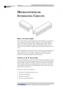
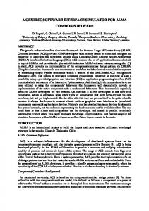
Interactive 6811 Simulator for Microcontroller Software Interfacing Jonathan W. Valvano Department of Electrical and Computer Engineering C0803 University of Texas at Austin Austin, Texas 78712 Abstract This paper presents a microcontroller hardware/software simulator which is used in a laboratory setting to educate undergraduate electrical engineering students. The specific objectives of the course include microcomputer architecture, assembly language programming, data structures, modular programming techniques, debugging strategies, hardware/software interfaces and embedded microcontroller applications. In this paper, I present both basic concepts and specific implementations which create an effective learning environment for my students. In particular, I wrote a DOS-based interactive simulator for the Motorola 6811. The application runs on a standard IBM-PC compatible with minimal requirements: Intel 386DX, 640K RAM, VGA color monitor, and 2 Megabytes of hard drive space. The student develops Motorola 6811 software which is cross-assembled and simulated. The major features of this interactive programming environment include user-configurable interactive external I/O devices, multiple display windows, extensive information available describing the activity both inside and outside the processor, elaborate protection against and explanation of programming errors, effective mechanisms for setting breakpoints, and user-defined “scan points” which allow the user program to interact with the graphics display.
Introduction Because the use of embedded microcontrollers has become pervasive in our economy, it is necessary to educate our engineers so they will be able effectively create the products of the future. The difficulty with teaching software/hardware interfacing on a workstation or personal computer is that the hardware technology has outpaced our software sophistication. We should be teaching our students to approach a software problem using classical engineering methods: 1) define the program; 2) develop alternative solutions, 3) consider the tradeoffs; 4) select a creative implementation which not only solves today’s problem, but leaves the door open for future enhancements; and 5) evaluate the final solution. The shear processing power and memory size of today’s computer technology has lead to a generation of “fat and lazy” programmers who solve their problems simply by using more advanced technology. The software development environments (like LabView and Visual BASIC), in an effort to keep up with the advancing hardware technology, have many sophisticated software tools which have a easy learning curve and allow a quick software implementation. These software development systems hide many of the fundamental computer engineering issues, so that the programmer can focus on his or her application. If your mission is to create and market products, then one can successfully argue that these software tools are effective. One the other hand, since our goal is to educate computer engineers, we must expose our students to the computer, and force them to face real engineering tradeoffs. In order to become better programmers, we teach our students assembly language on the Motorola 6811 embedded microcontroller because it exposes them to the fundamental computer architecture without overwhelming them with the complexities of today’s technology. At the same time, we show them the assembly language generated by the compiler so they understand the implications of their C programming.
Environment for Learning How to Write Quality Software This section presents five fundamental hypotheses that compose the framework of the class in general and the 6811 simulator in particular. Before we begin, it is important to separate the goals of our educational process from the needs of the professional engineer. In the teaching environment, we need software development tools which allow the student to learn in an effective manner the specific concepts of the course. On the other hand, in a professional engineering environment, the goal is to produce cost-effective products where the key
software development issues involve product planning, the management of the software team members, and creating code which is easy to maintain. Obviously, we hope our students graduate and become professional engineers. Nevertheless, since the educational and professional environments are different, it is reasonable that their optimal programming environments also be different. Computers are too fast Advances in computer technology have produced machines which process information at a tremendous rate. It is not possible for any human comprehend this mass of details in real time. We must either slow down the computer or filter the information. In the context of computer architecture, we are interested in the details, so it is more appropriate to slow down the computer. Microprocessor technology has developed complex features such as caches and internal buses which run at faster rates than external buses. In these systems, much of the activity which would help the student understand computer architecture is not observable on a real system. The educational objectives of computer architecture require the simulator to provide explicit information concerning things like the status of the ALU, memory bus cycles, and internal registers. On the other hand, applications like a PID motor controller, require less information about what’s going on inside the processor and more details about the external physical plant. When implementing a PID controller, we would like the system to simulate 6811 instructions as fast as possible, hiding the details occurring within the processor. Computers have too much memory There are two problems with providing the beginning programmer with unlimited amounts of memory. If students are raised in the environment where lots of memory is available, they will develop lazy habits which promote fat software. Clearly, we do not wish to squeeze every last byte of the code so that understanding and maintenance are compromised. But, it is good practice to address programming solutions like any engineering problem that has realistic constraints. In this way, we force them to consider alternative solutions and make decisions based on reasonable tradeoffs. The other problem arises from the fact that learning objectives are different from software features. I believe a student can learn the basic principles of linked-list data structures better by implementing a finite state machine with 10 states than she would by implementing one with a 100 states. Additional memory is required to add features which are important to the professional engineer and her customers, but often is counter-productive when the goal is to experience the basic principles. People are multisensory learners The ability to comprehend difficult concepts is enhanced when the material is presented in multiple formats. In the computer engineering context, we can convey information in text, colors, sounds, still pictures and movies. Color changes and sounds can be used to signal warnings that focus the student’s attention on important information. Interactive graphics provide alternate and effective mechanisms for displaying the status of the system. People learn in different ways and at different rates Individual people learn in different ways and at different rates. In addition, an individual person may need to adjust their learning process as they progress through the topics of a class. For these reasons, the learning environment must be flexible in its approach so that the student can adapt the environment to meet her current needs. In particular, the beginning student requires extensive protection and can benefit from simple “hand holding” tutorials. On the other hand, an advanced student requires features that stimulate and encourage her creativity. In a similar manner, some students are more effective learners at day than at night, or vice versa. For this reason, it is desirable for the system to be inexpensive and portable. In this way, the students can work at home, which has the added benefit of requiring less facilities on campus. Hard copy printouts are not cost effective. Laser printers are expensive to purchase and maintain. In addition, students tend to utilize a tremendous amount of printer supplies. Therefore, it is logical to assess whether the benefits justify the expenses. In my opinion, hard copy printouts may actually diminish the quality of software produced by the student. In particular, consider the goal of producing modular software. With a hard copy printout, the student is tempted to
combine software into a larger file which is easier to print than multiple smaller files. The interactions between multiple small files (modules) are harder to visualize from the printouts. On the other hand, viewing the software from a windowing environment encourages the programmer to organize the problem into smaller modules that more conveniently fit into the size of a single window. The limited screen space also forces the programmer to debug smaller modules independently. The other problem with printouts is that, during development, they are almost immediately obsolete. As a professor, I find it to harder to consult with a student who brings an obsolete printout to my office, than it is when she brings a current version on a floppy disk.
Figure 1. A typical display of the 6811 simulator application.
Implementation Windows Figure 1 illustrates some of the features of my 6811 simulator. The user can activate up to 14 configurable interactive windows. Eight of the windows provide interaction within the 6811 itself, and 6 more deal with the external I/O devices. The initial size and location of each window can be initialized in a configuration file. In addition, the sizes and locations can be dynamically modified using the mouse. For example, the student can temporarily increase the size of the stack window to observe more stack parameters, then restore the window back to its original size. The windows can be updated after every instruction for maximum visualization or updated less frequently to improve the simulation speed. User defined “scan points” are strategic places in their program which, when executed, will update the windows. Interpreter window. The user may type commands into the interpreter window. All aspects of the simulation can be controlled via this window. The students can define new commands (macros) which customize their system. The editor, assembler, and simulator are integrated so the edit-assemble-load-run cycle can be as short as 15 seconds for small edit changes. A s s e m b l y l i s t i n g w i n d o w . The assembly listing window displays the listing output of the assembler. You can type in a "Search for" string to find assembly labels within the file. It is color coded to
improve program understanding. For example, the current instruction is colored red, the breakpoints are yellow, and a “Search for” string is cyan. 6811 status windows. The CCR, register, and port windows display the 68HC11 registers and I/O ports. The display format of each parameter can be individually configured to binary, hexadecimal, octal or decimal. In addition, the display can be set to signed or unsigned. Which ports to display and the display format can be individually configured. Notice in Figure 1 that the DDRC is configured for binary display while the other ports are in hexadecimal. The I/O port windows in Figures 1 and 2 are configured differently. Stack Window. The stack window displays the 68HC11 stack. The format and precision can be specified. You can also move the display up/down using command codes. The system knows the stack area, so that it can detect if the stack underflows or overflows. Local variables are easy to see dynamically. Memory Window. The memory display window is used to observe global variables. Which variables and the display format can be initially configured, and modified dynamically. Help Window. The help window contains context-specific information on line. It provides interactive assistance for all stages of the program development process. It also includes answers to the “most frequently asked” questions.
Figure 2. A display illustrating the DC motor controller.
External I/O Devices Terminal port. The Serial Communication Interface Window simulates a ASCII terminal connected to the 6811 SCI port. ASCII characters can be Input/Output to this window. The baud rate can be adjusted. The inputs come from the PC keyboard and the outputs go to the SCI window. The real time nature of this interface is simulated. Input switches. The switch input window recreates digital inputs which can be attached to the 6811 parallel ports. The student uses the mouse to toggle the switch position. The user can connect a switch to any input pin. The simulator allows up to 16 binary (2-pole) switches. The user adds text labels to each switch. If a switch is attached to bi-directional port, and the student’s software incorrectly initializes the port as an output,
an error is generated. The user program reads from the input port to get the current switch position. Figures 1 and 2 illustrate examples of switch inputs. Output l i g h t emitting diodes (LED). Binary outputs can be displayed in this window. The user can connect a LED to any input or output pin. The simulator allows up to 32 LED’s organized in a rectangular pattern. The user can choose red or green LED color, and specify to which 6811 pins the LED’s are connected. The user adds text labels to each LED. The user program writes to the output port to turn the LED on and off. If the user connects a switch and a LED to an input port, then the LED is controlled directly from the switch. Figure 1 has 8 LED’s connected to Port B. 7 segment liquid crystal display (LCD). Binary Coded Decimal outputs can be displayed in this window. An optional sign bit can be connected, and each digit can be connected to a group of four I/O pins. The decimal digit is encoded in binary-coded-decimal (BCD). The user configures the pin connections and adds title, tag, and unit labels to the display. The user program writes to the output port to set the 7 segment LCD. If the user connects switches and a 7 segment LCD to 4 input ports, then the display is controlled directly from the switches. Figure 1 shows a LCD display connected to Port B. Variable speed DC motor with tachometer. Information about the motor is displayed in two windows: the motor status window and the motor plot window. U is the D/A output in mV., V is the applied power to the DC motor in mN, S is the current motor speed in rpm, and X is the A/D input from the tachometer in mV. From Figure 2, you can see that the first derivative of these parameters is also displayed. The physical plant is modeled numerically as a second order differential equation with a fixed mass, and variable friction. The motor plot window displays this information as a real time scroll graph. The user configures the system by selecting which ports to attach the D/A and A/D signals. The student’s 6811 program controls the motor speed by writing to the output port to which the D/A is connected, and estimates the current shaft speed by reading the appropriate A/D input channel. Stepper motor car. The car has two stepper motors on its back wheels and is equipped with front and back bumper switches. Each wheel motor can be independently rotated to control both the direction and speed of the car. The stepper motors are attached to output ports of the 6811, and the bumper switches are attached to 6811 input ports. Up to 20 objects may be placed in the simulated field to obstruct the car motion. Figure 3 shows an example configuration file which attaches the stepper motor to Port B, connects the bumper switches to Port A and defines 3 objects in the simulated field. PortB AddStepper Bit0 PortA Back AddBumper Bit1 PortA Front AddBumper 300 400 AddObject 400 700 AddObject 100 500 AddObject Figure 3. Configuration commands which connect a car to Ports A, B and adds three objects.
The user’s 6811 program writes to the stepper motor output port to move the two stepper motors, and reads from the input port to detect if the car has hit an object or wall. The scatter plot window, as illustrated in Figure 4, shows the current car position and direction. The current state of the car and its stepper motors is displayed in the motor position window. The simulated car is updated on every write to output port. Like a real stepper motor, the user’s 6811 program must output the proper sequence (e.g., 5,6,10,9) to rotate the wheel. Extensive information and protection is available With the appropriate option enabled, you see for each memory cycle all the information shown in Table 1. Elaborate protection against program errors provides the student with a friendly environment to program. It will halt on an illegal opcode fetch, detect a write to ROM operation, detect a read from uninitialized RAM, and detect an access to an illegal address. The user has the option of ignoring, showing warning or halting execution on these errors. Detailed error messages provide the student with insight as to potential reasons for the error. Up to ten breakpoints can be set. The program can break on any read/write memory or
Input/Output access, not simply when the PC fetches an opcode from a specified location. The user can set breakpoints using assembly symbols or assembly listing. TCNT RW Address Data Comments IR EAR ALU CCR
16 bit free running up counter R means read from memory, W means write to memory 16 bit 68HC11 address 8 bit 68HC11 data bus Describes what kind of bus cycle it is Instruction Register contains the opcode Effective Address Register Arithmetic Logic Unit operation and result 68HC11 Condition Code Register
Table 1. Available information for each memory cycle.
Figure 4. A display illustrating the stepper motor car.
Conclusions I use a simulator because it allows my students to visualize their hardware - software interactions. The simulator provides windows into the processor architecture (e.g., the ALU and effective address register), as well as the usual information (e.g., memory, registers, stack, I/O ports.) Student can interface many external devices to the 6811 using an interactive command language. The external devices are those typically connected to embedded microcontrollers: switch inputs, LED light outputs, 7 segment displays, keyboard, CRT display, D/A, stepper motor car, and a variable speed DC motor. The simulator provides an effective tool for the education of the beginning computer engineer.