Interactive Design of Botanical Trees using Freehand. Sketches and Example-
based Editing. Makoto Okabe1, Shigeru Owada1,2 and Takeo Igarashi1,3.
EUROGRAPHICS 2005 / J. Marks and M. Alexa (Guest Editors)
Volume 24 (2005), Number 3
Interactive Design of Botanical Trees using Freehand Sketches and Example-based Editing Makoto Okabe1 , Shigeru Owada1
2
and Takeo Igarashi1
3
The University of Tokyo1 , Sony CSL2 and JST PRESTO3
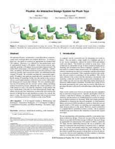
Abstract We present a system for quickly and easily designing three-dimensional (3D) models of botanical trees using freehand sketches and additional example-based editing operations. The system generates a 3D geometry from a twodimensional (2D) sketch using the assumption that trees spread their branches so that the distances between the branches are as large as possible. The user can apply additional gesture-based editing operations such as adding, cutting, and erasing branches. Our system also supports example-based editing modes in which many branches and leaves are generated by using a manually designed tree as an example. User experience demonstrates that our interface lets novices design a variety of reasonably natural-looking trees interactively and quickly. Categories and Subject Descriptors (according to ACM CCS): I.3.6 [Computer Graphics]: Methodology and Techniques - Interaction Techniques
1. Introduction 3D models of botanical trees are important in geographical landscape simulation, cityscape design, virtual reality, consumer games, and other fields of 3D graphics. However, designing tree models is challenging because trees have enormous structural complexity. There are two major methods for obtaining tree models. One is a rule-based approach, such as L-systems, and the other method places predefined generic models in a library or modifies their parameters. Rule-based systems allow users to design a wide variety of realistic trees. However, it is difficult for novice users to design trees of the desired appearance using rule-based systems because the inputs to such systems (rules and parameters) are very different from their output (3D geometry). Moreover, while one can quickly obtain typical trees by using predefined generic models, it is often difficult or impossible to design a desired tree by modifying predefined models. This paper proposes a system for designing 3D botanical trees based on a sketching interface and example-based control. Sketch-based interfaces [ZHH96][IMT99] facilitate the rapid construction of 3D models and programming-byexample interfaces [Cyp91][MWK89] by automating repetitive operations. Our contribution is to propose intuitive mod-
c The Eurographics Association and Blackwell Publishing 2005. Published by Blackwell Publishing, 9600 Garsington Road, Oxford OX4 2DQ, UK and 350 Main Street, Malden, MA 02148, USA.
eling interfaces for trees, which free the user from complicated rules or parameters. The modeling process in rulebased systems can be seen as a deductive process, in that the final 3D geometry is derived from abstract production rules. Our sketch-based method can be seen as an inductive process, in that the user specifies the 2D appearance of the model directly and the system then generates a 3D structure by inferring hidden parameters. The main purpose of our system is to construct 3D tree geometries from users’ 2D sketches based on the simple assumption that botanical trees tend to spread their branches in such a way that the distances between branches are as large as possible. This enables the user to design 3D tree geometries intuitively using standard 2D input devices. This assumption is an overly simplistic description of the growth process of real trees, but it is fast and general enough for quickly designing reasonable-looking trees from typical sketches. Our algorithm also considers the fact that most users draw branches that extend sideways and omit those that extend toward or away from the screen. In addition to the sketching interface, our system also supports three example-based editing modes: branch multiplication, leaf arrangement, and branch propagation. These editing modes allow the user to construct complicated trees by providing a few examples and free the user from drawing
M. Okabe, S. Owada & T. Igarashi / Interactive Design of Botanical Trees using Freehand Sketches and Example-based Editing
Figure 1: Simple 2D sketches of botanical trees (above) and 3D polygon models, which are a red young tree, a zelkova, and a maidenhair tree (below). The initial 3D trees were created from the 2D sketches automatically using our algorithm. Additional branches and leaves were then attached to the trees using our prototype system. Each process took several minutes.
all individual branches or specifying rules or parameters directly. Figure 1 shows sample 2D sketches and the resulting 3D trees created using our system. Our goal is not to simulate the principles of nature, but to assist the user’s creative design process. Our system supports several semi-automatic modeling functions that simulate some of the morphological properties of natural trees, but the user’s intention expressed in the input sketch always has higher priority. Our current prototype system is designed only for trees, but many of the proposed interfaces can be used to design other 3D plants, such as flowers. 2. Previous Work 2.1. Modeling Plants Lindenmayer proposed the formalism of L-systems [Lin68], and Prusinkiewicz improved them [PHHM96]. Subsequent research has expanded L-systems for simulating a wide range of interactions between a plant and its environment [PJM94][MP96], and for increasing realism and supporting the interactive modeling process by using positional information [PMKL01]. Boudon proposed a method to create trees more intuitively and interactively taking advantage of L-systems and demonstrated their method by creating models of bonsai trees [BPF� 03]. Some other rule-based
approaches have also been proposed to address the limitations of older L-systems [AK84][WP95]. Deussen and Lintermann developed the Xfrog system in order to combine the power of a rule-based approach with the intuitiveness of generic tree methods [DL97][LD99]. Deussen also proposed a non-photorealistic rendering method for 3D trees [DS00] that represents leaves as simple particles.
Other research has attempted to reconstruct 3D tree geometry from multiple photographs. Sakaguchi derived 3D volume data from multiple photographs of a tree and reconstructed 3D tree geometry by growing it upwards from its roots [SO99], but this method can produce undesirable geometries and needs some heuristics. Shlyakhter proposed a method that uses a visual hull to construct a trunk and major branches and an L-system for finer branches [SRDT01]. Reche proposed a method to capture a real-world tree as a volume with opacity and color values [RMMD04]. Maierhofer and Tobler proposed a user interface that makes it easier to specify modeling parameters by replacing numerical parameters with a more intuitive set of graphical modeling primitives [MT02]. Ijiri adopted the notion of floral diagrams and inflorescences, and proposed a method to design flowers, while preserving correct botanical structures [IOOI05].
c The Eurographics Association and Blackwell Publishing 2005.
M. Okabe, S. Owada & T. Igarashi / Interactive Design of Botanical Trees using Freehand Sketches and Example-based Editing
2.2. Sketch-based 3D Modeling Many researchers have proposed methods for constructing 3D models from user-defined 2D drawings. These include the reconstruction of rectilinear models covered by planar faces by solving constraints [EyHBE97] or using optimization-based algorithms [SL96a][SL96b], the reconstruction of the 3D geometry of a 3D curve using energy minimization [PK89], and using symmetric relations [TNT89]. Our particular interest is an interactive sketching interface for designing 3D models using 2D gestures. The Sketch system [ZHH96] is for designing 3D scenes consisting of simple primitives, and the Teddy system is for designing freeform models [IMT99]. Several extensions of the original Teddy system have recently been proposed [ONOI04].
branch-propagation mode copies the child branches of a parent branch to other parent branches (Figure 2 (e)). The user can undo or redo any actions while modeling a tree by pressing the "Undo" or "Redo" button.
(a) 2D Sketch
(d) Leaf-arragement
2.3. Example-based Interfaces The user interface research community has been investigating example-based user interfaces in which the computer automates some of the repetitive tasks by observing a user’s example operation [Cyp93]. The Eager system detects repetition in the user’s operation and suggests automation [Cyp91]. In the Metamouse system, the user explicitly trains the system by demonstration [MWK89]. Igarashi et al. [IMKT97][IKTM98] implemented a prediction mechanism on top of their beautification-based 2D drawing system. Their system predicts the user’s next drawing operation based on the drawing already in the scene and displays the predicted results as multiple candidates. This helps the user to design relatively complicated scenes without drawing all of them manually. This idea has been extended to 3D-model design [IH01]; like the 2D version, this system suggests operations that the user is likely to do next. 3. User Interface for Modeling Trees 3.1. Overview First, we overview the process of modeling a typical 3D tree (Figure 2). The user begins to model a 3D tree by sketching a simple 2D tree using a mouse or pen tablet (Figure 2 (a)). After sketching a tree, the user presses the "3D" button and the system constructs 3D tree geometry from the 2D sketch (Figure 2 (b)). This process takes several seconds. Now the user has a 3D tree, and manually adds or removes branches with simple gestures. The user can also apply example-based editing modes to generate complicated trees. The user switches between modes by pressing the corresponding buttons. In branch multiplication mode, the user can add more child branches to a designated parent branch using the existing child branches as examples (Figure 2 (c)). The leaf-arrangement mode lets the user place leaves around a branch following typical leaf arrangement patterns by providing a few examples (Figure 2 (d)). Finally,
c The Eurographics Association and Blackwell Publishing 2005.
(b) 3D Construction
(c) Multiplication
(e) Propagation
Figure 2: (a) The user draws a 2D sketch of a tree; (b) the system generates a 3D tree when the user presses the 3D button; (c) a denser 3D tree model is obtained in multiplication mode; (d) leaves are added to a branch in leaf-arrangement mode; and (e) leaves are propagated to other branches in propagation mode.
3.2. Sketching a 2D Tree The user begins to model a 3D tree by sketching simple 2D strokes that represent branches or leaves. An open stroke makes a branch and a loop stroke makes a leaf polygon as a bounding box for the stroke (Figure 3). An incoming stroke is connected to the nearest existing branch and becomes its child branch or leaf. When a branch is attached to a parent it changes its form so that it is connected to its parent precisely. The base point moves to the nearest point along the parent branch; the terminal point remains fixed; and the displacements of the intermediate points are interpolated.
(a)
(b)
(c)
(d)
Figure 3: Drawing a branch (a-b) and drawing a leaf (c-d).
When the user draws a branch using a single stroke, the system applies default geometry (varying radii along the branch) to the branch. Optionally, the user can draw a pair of almost parallel strokes to define the detailed shape of the branch. The two strokes correspond to the silhouette of the branch (Figure 4). The system sweeps a circle along the two strokes to construct the branch geometry. After a detailed
M. Okabe, S. Owada & T. Igarashi / Interactive Design of Botanical Trees using Freehand Sketches and Example-based Editing
geometry has been specified using a pair of strokes, that geometry becomes the default setting and is then applied to subsequent branches drawn as single strokes.
also edit branches or leaves by drawing cutting and erasing strokes. 3.4. Example-based Branch Multiplication
(a)
(b)
Figure 4: Two strokes representing a branch’s silhouette (a) and the resulting 3D branch geometry (b). The user can edit branches using two gestural editing operations: cutting and erasing. An editorial stroke intersecting a branch once cuts the branch. The distal end of the branch is erased, as are all the descendant nodes spawned on that side. An editorial stroke intersecting a branch two or more times erases the branch. In this case, all the descendant nodes are erased.
In this editing mode, the user can click a branch to increase the density of its child branches, while preserving the overall appearance of the tree. Each click adds a new branch to the parent branch; the user can add as many branches as desired by successive clicking. Figure 6 shows an example. The detailed algorithm for computing the position, orientation, and shape of the new branch is given in Section 4.3.
(a)
(b)
Figure 6: The user adds child branches to a branch by successive clicking.
3.3. Creating a 3D Tree from a 2D Sketch The system constructs a 3D tree when the user finishes drawing a 2D tree and requests its construction by pressing the "3D" button. (This takes several seconds.) After construction, the user can rotate the tree and see it from different viewpoints. Figure 5 shows some examples. The basic strategy is to make trees spread their branches so that the distances between them are as large as possible. The system also gives detailed depth modulation to each branch. The algorithm is described in Section 4.
3.5. Example-based Leaf Arrangements This mode allows the user to place leaves according to typical leaf-arrangement patterns (alternating patterns and whorled patterns). The interface is similar to the user interfaces proposed by Igarashi and Hughes [IH01]. The user adds a few sample leaves manually and the system infers possible arrangement patterns from these examples. The system then generates further leaves based on the inferred patterns and shows the results as thumbnail previews (Figure 7). When the user likes a result, he or she clicks the corresponding thumbnail to use it. If the user does not like the result, he or she can ignore it and proceed to the next operation. The current implementation supports three suggestion engines. One adds leaves to the base of a given set of whorled leaves. Figure 8 shows an example. When the system observes a set of leaves at the same base position, it infers that the user wants to use the whorled pattern and adds a leaf to the set. The system also rearranges the existing leaves so that they are distributed around the parent branch equally. The user can increase the number of leaves by clicking the corresponding thumbnail successively (Figure 8).
Figure 5: The upper snapshots are freehand sketches, and the lower snapshots are the results of 3D construction. After constructing a 3D tree, the user can add a branch or a leaf by drawing a stroke as in the 2D case. The 2D strokes are projected onto a plane that is parallel to the screen and passes through the base point on the parent branch. The user can
Another engine extends the whorled leaves along the parent branch (Figure 9). When the system observes a set of whorled leaves attached to a base position and a leaf at a different position, it infers that the user wants to add more sets of whorled leaves with the given spacing. The system fills the remaining region of the parent branch with sets of whorled leaves. The final engine extends alternate leaves along the parent
c The Eurographics Association and Blackwell Publishing 2005.
M. Okabe, S. Owada & T. Igarashi / Interactive Design of Botanical Trees using Freehand Sketches and Example-based Editing
Figure 10: Extending alternating leaves along the parent branch.
the user switches between them using a toggle button on the screen.
Figure 7: Thumbnails are presented to the user. The user can adopt a prediction result by clicking the corresponding thumbnail. (a)
(b)
(c)
Figure 11: The original state of a tree (a), propagation with scaling (b) and propagation without scaling (c). Figure 8: Increasing the number of leaves in a set of whorled leaves.
branch (Figure 10). When the system observes two leaves placed at different positions, it infers that the user wants to use the alternating pattern and adds additional leaves along the parent branch. The system uses the rotational angle between the sample leaves to place new branches, generating spirally arranged leaves. 3.6. Example-based Branch Propagation This editing mode lets the user propagate the local arrangement of branches and leaves to the entire tree. When the user clicks a branch (reference branch), the system copies the child branches and leaves of the reference branch and pastes them on all other branches (target branches) on the tree. The current system supports two types of propagation;
Figure 9: Extending whorled leaves along the parent branch.
c The Eurographics Association and Blackwell Publishing 2005.
One type of propagation is that with scaling (see Figure 11 (b)). When the system pastes the child branches and leaves on a target branch, it scales them so that the reference branch matches the target branch. This mode is useful for propagating detailed branching to other branches. In propagation without scaling (Figure 11 (c)), the system pastes the child branches and leaves without scaling. The tip of the reference branch is placed at the tip of the target branch. If the target branch is shorter than the reference branch, the system uses only the child branches and leaves near the tip of the reference branch. This mode is useful for propagating leaves around the reference branch because all the leaves are of similar size and spacing all over the tree.
3.7. Reproduce a Tree from Overall Sketching Once the entire modeling process is completed, the user can duplicate the finished model using two strokes representing the trunk and the silhouette of the new one (see Figure 12 and Figure 19). Several previous systems take advantage of silhouettes to specify the overall shape of a tree, and these inspired our user interface [BPF� 03][PJM94][PMKL01][WP95]. The system changes the shape of the trunk and adjusts the length of each segment to fit into the silhouette, while other properties, such as the branching structure or the number of segments, remain fixed. This operation is useful for generating multiple trees that have the same structure, but different appearances.
M. Okabe, S. Owada & T. Igarashi / Interactive Design of Botanical Trees using Freehand Sketches and Example-based Editing
Figure 12: The original tree (left) and a tree reproduced by sketching the trunk (orange) and the overall shape (blue)(right). Figure 13: Computing the depth information for branches with the 2D distance field. 4. Algorithm This section provides a detailed explanation of the algorithms used to compute 3D tree geometries based on sketches and examples. We focus on only the most relevant aspects, omitting the explanation of relatively straightforward processes because of space limitations.
essary in order to give the branches that touch the hull the freedom to move away from the original plane.
4.1. Creating a 3D Tree from a 2D Sketch The task here is to compute the depth information for the branches. The goal is to make the tree look similar when viewed from all angles, preserving the appearance from the original viewpoint. Our basic strategy is to adjust the orientation of a branch so that the distances between it and other branches are as large as possible (Figure 13). We use a greedy approach (adding branches one by one) instead of computing a globally optimal branch placement. The order of processing sibling branches is random. Ideally, we would construct a 3D volume whose voxels contain the distance to the nearest branch and then place the branch whose voxels have maximum distance values. Unfortunately, it is too computationally expensive to update the volumetric distance field for each added branch. Therefore, we project all branches to the ground and construct a 2D distance field, computing distances from the projected branches to each pixel (Figure 13, bottom). Our current implementation, which uses a 128 128 distance field, makes an exhaustive search for the optimal placement.
¢
The projection of 3D branches onto the screen must fit the 2D sketch. This means that if we extended a branch in the direction almost perpendicular to the screen, the distance field alone could not prevent branches from protruding excessively from the overall silhouette (the maximum distance value is a branch of infinite length). To prevent this, we restrict the search to within a 3D hull constructed from a 2D convex hull around the given sketch. To construct the 3D hull, we simply sweep a circle along the 2D convex hull, starting from the bottom and ending at the top, and enlarge it by a constant value ( 2) (Figure 14). Magnification is nec-
Ô
(a)
(b)
Figure 14: A 2D convex hull of the original sketch (a). The resulting 3D convex hull after magnification (b).
Our algorithm also constrains the lengths of branches, because a branch is generally shorter than its parent branch. We use the formula introduced in Weber and Penn [WP95] to calculate the length of a child branch. To relax the constraint, we magnify the calculated value using a constant (the current implementation uses 1.2). We use this constraint over branches other than the trunk and its child branches. Our algorithm further constrains the angles between a parent branch and its child branches. We first calculate the maximum angle between a parent branch and its child branches in the 2D sketch. Then, we compute a limit angle by multiplying the maximum angle times a constant (we use 1.2). Finally, we constrain the angles between the parent branch and its children to be smaller than the limit angle. During this process, for simplicity and efficiency we treat each branch as a straight-line segment that connects the base and terminal points. After constructing a 3D tree consisting of straight branches, we assign depth modulation to the curves shown in the original 2D sketch. For depth modulation, we adopt the algorithm described in [IOOI05], which was proposed to
c The Eurographics Association and Blackwell Publishing 2005.
M. Okabe, S. Owada & T. Igarashi / Interactive Design of Botanical Trees using Freehand Sketches and Example-based Editing
front view
add appropriate depth to a user-drawn 2D stroke in an inflorescence editor.
side view
4.2. Extension of the Basic Algorithm People tend to draw branches that extend sideways and omit branches extending toward or away from the screen. However, our basic algorithm tries to spread branches in all directions uniformly, and the resulting 3D tree looks very different when viewed from the side (Figure 15). front view
branch, the system must determine its position, length, orientation, and shape. Position, length, and shape are simple: the system places the new branch between the most separated pair of neighboring branches. The length of the branch is the average of the neighboring sibling branches. As for the shape, we randomly choose one of the sibling branches on the parent branch and copy it.
side view
Figure 15: The resulting tree is strange when viewed from the side. To solve this problem, we assume that the user draws only branches that extend sideways, and we make the system automatically add branches that extend toward and away from the screen. We do this by constraining the direction of a branch within specific angles relative to the viewing direction (we use angles between 45 and 135 degrees). The system constructs two 3D trees using the algorithm described above, rotates one of them 90 degrees around the vertical vector, and merges it with the original tree, except for the main trunk (Figure 16). The two trees are slightly different because our algorithm spreads sibling branches in a random order. This simple ad hoc trick works very well and is an indispensable tool in the system. The merged tree looks similar when viewed from both the front and the side (Figure 17).
Orientation is a bit more complicated. The system first assigns consistent local coordinate systems along the parent branch using the "turtle" of L-systems [PHHM96]. The orientation of a child branch is determined by two angles in this local coordinate system: a "rotation angle" defined in the plane perpendicular to the parent branch, and a "down angle", which is the angle between the parent branch and the child branch (Figure 18).
Up vector
Child branch Down angle
Rotation angle
Parent branch (head vector)
Left vector
basic algorithm merging
basic algorithm
Figure 17: The merged tree looks similar when viewed from both the front and the side.
rotating 90 degrees
Figure 16: The system adds branches to the front and the back. Snapshots, except for the first sketch, are seen from the top.
Figure 18: A direction vector of a new child branch consisting of a rotation angle and a down angle. The rotation angle is calculated so that the new child branch spreads uniformly when seen along the head vector. Since a natural branch tends not to grow downward because of tropisms, we mimic the effect by calculating the rotation angle so that the child branch does not make an angle larger than 120 degrees with the upward vector perpendicular to the ground. A down angle is calculated as the average of the down angles of the neighboring sibling branches, as is the case with length.
4.3. Example-based Branch Multiplication This operation adds a new branch to a given parent branch using the existing child branches as examples. To add a
c The Eurographics Association and Blackwell Publishing 2005.
4.4. Reproduce a Tree from Overall Sketching The user-guided duplication algorithm is as follows:
M. Okabe, S. Owada & T. Igarashi / Interactive Design of Botanical Trees using Freehand Sketches and Example-based Editing
¯ ¯ ¯ ¯
Generate a new trunk that follows the user-drawn trunk stroke. The user-drawn silhouette stroke is converted into a 3D convex hull, using the algorithm described in Section 4.1. The length of the first-generation branches is adjusted so that they touch the 3D convex hull. The ratio is stored in each first-generation branch. Modify the length of second-generation or younger branches using the ratio stored in the ancestral firstgeneration branch. If the resulting length is longer than the 3D convex hull, adjust the length so that it touches the hull.
Since first-generation branches tend to decide the overall shape of a tree [WP95], they are processed differently from subsequent-generation branches. 5. Results Figure 1 and Figure 20 show 3D tree models designed by the authors. In Figure 1, the young red tree consists of 7,900 nodes (branches and leaves), the zelkova consists of 30,000 nodes, and the maidenhair tree consists of 4,900 nodes. We spent less than 10 minutes on average to design each of these models. We created broadleaf trees mainly from a 2D sketch and by propagating branches and leaves. The automatic multiplication was useful for designing branches of an acicular tree. We performed a user study to test the usability of our prototype system. The subjects were seven students in the Computer Science department who were novice users of our system. After having them read a tutorial and learn how to use our system, we asked them to create as many 3D trees as they liked. Most subjects spent approximately 1 hour on the study, while one subject was fascinated by the system and spent a day playing with it. Figure 21 shows tree models designed by four users and the time to complete each tree model. Some of these model trees are not natural in appearance, but they are what the users wanted. These unique trees might be difficult to design using rule-based systems or by modifying predefined tree models. We also performed another informal study to compare our system with existing methods. We used cpfg [PMKL01] as an example of a text-based system and Xfrog as an example of a graphical system. We recruited three novice users to join the study and asked them to create 3D trees like the target shown in Figure 22 (a). Figure 22 shows the resulting tree models created using cpfg (b), Xfrog (c), and our system (d and e). Two test users worked together for approximately 60 minutes to create the cpfg model. Another test user spent 30 minutes to create the Xfrog model. Finally, each test user worked individually using our system and took 10 minutes to create their models. These results show that our system is good at reconstructing the major branching structures of a tree, while the other systems are good at reconstructing de-
tailed structures. We would like to combine these two complementary approaches in the future. 6. Limitations and Future Work Our system allows the user to design various interesting treelike shapes quickly. This rapid construction is possible because we ignore some natural principles. As a result, the final models sometimes exhibit artifacts not seen in conventional tree-modeling systems. In the future, we plan to explore methods to fill the gap between speedy systems and systems that adhere to the processes of nature. For example, the current implementation does not handle tropisms explicitly. We plan to estimate tropisms from user-defined branches and apply them to system-created branches. We have designed our prototype so that it uses linear workflow, except for undo or redo. To make the system usable for practical applications, it should be able to edit trees. In the future, we plan to develop more sophisticated 3D interactions in our prototype system, which would allow the user to move, rotate, or bend individual or groups of branches on a completed tree without destroying leaves. Our user interfaces can be applied to 3D plants other than trees by implementing some additional interfaces. For example, we plan to implement sketch-based 3D interfaces for generating more complex leaf and flower models. We also plan to develop more leaf-arrangement engines, to handle other leaf patterns. The current system is designed to construct a single tree. We are also interested in the construction of similar, but slightly different, trees to create a forest, and are experimenting with algorithms that generate slightly different trees by tweaking the parameters used in the construction process.
(a)
(b)
Figure 19: An example of reproduction of a tree. (a) an original tree, (b) the reproduced version.
References [AK84]
AONO M., K UNII T. L.: Botanical tree image generation. IEEE Computer Graphics and Applications 4, 5 (1984), 10–34. 2
c The Eurographics Association and Blackwell Publishing 2005.
M. Okabe, S. Owada & T. Igarashi / Interactive Design of Botanical Trees using Freehand Sketches and Example-based Editing
(a)
(b)
(c)
Figure 20: 3D trees designed by one of the authors. (a) Cherry, (b) Pine, (c) Oriental Plane.
(a) 6 min
(b) 6 min
(c) 9 min
(d) 7 min
Figure 21: 3D tree models designed by the test users and the time to complete each tree model.
[BPF� 03]
B OUDON F., P RUSINKIEWICZ P., F EDERL P., G ODIN C., K ARWOWSKI R.: Interactive design of bonsai tree models. Comput. Graph. Forum 22, 3 (2003), 591–600. 2, 5
[IH01]
I GARASHI T., H UGHES J. F.: A suggestive interface for 3d drawing. In Proceedings of UIST 2001 (2001), ACM Press, pp. 173–181. 3, 4
[Cyp91]
C YPHER A.: Eager: Programming repetitive tasks by example. In Proceedings of CHI ’91 (New Orleans, LA, 1991), pp. 33–39. 1, 3
[IKTM98]
[Cyp93]
C YPHER A.: Watch What I Do: Programming by Demonstration. Cambridge, MA: MIT Press, 1993. 3
I GARASHI T., K AWACHIYA S., TANAKA H., M ATSUOKA S.: Pegasus: a drawing system for rapid geometric design. In Proceedings of CHI ’98 (1998), ACM Press, pp. 24–25. 3
[IMKT97]
I GARASHI T., M ATSUOKA S., K AWACHIYA S., TANAKA H.: Interactive beautification: a technique for rapid geometric design. In Proceedings of UIST ’97 (1997), ACM Press, pp. 105–114. 3
[IMT99]
I GARASHI T., M ATSUOKA S., TANAKA H.: Teddy: a sketching interface for 3d freeform design. In Proceedings of SIGGRAPH ’99 (1999), ACM Press, pp. 409–416. 1, 3
[IOOI05]
I JIRI T., OWADA S., O KABE M., I GARASHI T.: Floral diagrams and inflorescences: Interactive flower modeling using botanical structural constraints. In Proceedings of SIGGRAPH 2005 (2005), ACM Press. 2, 6
[DL97]
[DS00]
D EUSSEN O., L INTERMANN B.: A modelling method and user interface for creating plants. In Graphics Interface (May 1997), Davis W., Mantei M.„ Klassen V., (Eds.), pp. 189–197. 2 D EUSSEN O., S TROTHOTTE T.: Computergenerated pen-and-ink illustration of trees. In Proceedings of SIGGRAPH 2000 (2000), ACM Press, pp. 13–18. 2
[EyHBE97] E GGLI L., YAO H SU C., B RÜDERLIN B. D., E LBER G.: Inferring 3d models from freehand sketches and constraints. Computer-Aided Design 29, 2 (1997), 101–112. 3
c The Eurographics Association and Blackwell Publishing 2005.
M. Okabe, S. Owada & T. Igarashi / Interactive Design of Botanical Trees using Freehand Sketches and Example-based Editing
(a) target
(b) cpfg
(c) XFrog
(d) our system
(e) our system
Figure 22: 3D tree models designed using the different systems by the test users. (a) The target tree, (b) the result of cpfg by two users, (c) the result of XFrog and (d, e) the results of our system.
[LD99]
L INTERMANN B., D EUSSEN O.: Interactive modeling of plants. IEEE Comput. Graph. Appl. 19, 1 (1999), 56–65. 2
[Lin68]
L INDENMAYER A.: Mathematical models for cellular interactions in development. Journal of Theoretical Biology 18 (1968), 280–315. 2
[MP96]
ˇ R., P RUSINKIEWICZ P.: Visual models M ECH of plants interacting with their environment. In Proceedings of SIGGRAPH ’96 (1996), ACM Press, pp. 397–410. 2
[MT02]
M AIERHOFER S., T OBLER R. F.: Creation of realistic plants using semi-automatic parametric extraction from photographs. Technical report 2002-002, VRVis Research Center (2002). 2
[MWK89]
M AULSBY D. L., W ITTEN I. H., K ITTLITZ K. A.: Metamouse: specifying graphical procedures by example. In Proceedings of SIGGRAPH ’89 (1989), ACM Press, pp. 127–136. 1, 3
[ONOI04]
OWADA S., N IELSEN F., O KABE M., I GARASHI T.: Volumetric illustration: designing 3d models with internal textures. ACM Trans. Graph. 23, 3 (2004), 322–328. 3
[PHHM96] P RUSINKIEWICZ P., H AMMEL M., H ANAN ˇ J., M ECH R.: L-systems: from the theory to visual models of plants. Proceedings of the 2nd CSIRO Symposium on Computational Challenges in Life Sciences. (1996). 2, 7 [PJM94]
[PK89]
ˇ R.: P RUSINKIEWICZ P., JAMES M., M ECH Synthetic topiary. In Proceedings of SIGGRAPH ’94 (1994), ACM Press, pp. 351–358. 2, 5
P ENTLAND A., K UO J.: The artist at the in-
terface. Vision Science Technical Report 114. (1989). 3 [PMKL01]
P RUSINKIEWICZ P., M ÜNDERMANN L., K ARWOWSKI R., L ANE B.: The use of positional information in the modeling of plants. In Proceedings of SIGGRAPH 2001 (2001), ACM Press, pp. 289–300. 2, 5, 8
[RMMD04] R ECHE -M ARTINEZ A., M ARTIN I., D RETTAKIS G.: Volumetric reconstruction and interactive rendering of trees from photographs. ACM Trans. Graph. 23, 3 (2004), 720–727. 2 [SL96a]
S HPITALNI M., L IPSON H.: Identification of faces in a 2d line drawing projection of a wireframe object. IEEE Trans. Pattern Anal. Mach. Intell. 18, 10 (1996), 1000–1012. 3
[SL96b]
S HPITALNI M., L IPSON H.: Optimizationbased reconstruction of a 3d object from a single freehand line drawing. Computer-Aided Design 28, 8 (1996), 651–663. 3
[SO99]
S AKAGUCHI T., O HYA J.: Modeling and animation of botanical trees for interactive virtual environments. In Proceedings of VRST ’99 (1999), ACM Press, pp. 139–146. 2
[SRDT01]
S HLYAKHTER I., ROZENOER M., D ORSEY J., T ELLER S.: Reconstructing 3d tree models from instrumented photographs. IEEE Comput. Graph. Appl. 21, 3 (2001), 53–61. 2
[TNT89]
TANAKA T., NAITO S., TAKAHASHI T.: Generalized symmetry and its application to 3d shape generation. The Visual Computer 5, 1&2 (1989), 83–94. 3
[WP95]
W EBER J., P ENN J.: Creation and rendering of realistic trees. In Proceedings of SIGGRAPH ’95 (1995), ACM Press, pp. 119–128. 2, 5, 6, 8
c The Eurographics Association and Blackwell Publishing 2005.
M. Okabe, S. Owada & T. Igarashi / Interactive Design of Botanical Trees using Freehand Sketches and Example-based Editing
[ZHH96]
Z ELEZNIK R. C., H ERNDON K. P., H UGHES J. F.: Sketch: an interface for sketching 3d scenes. In Proceedings of SIGGRAPH ’96 (1996), ACM Press, pp. 163–170. 1, 3
c The Eurographics Association and Blackwell Publishing 2005.