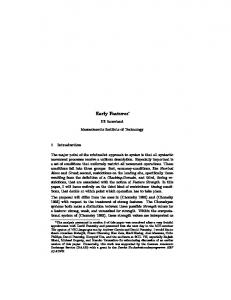
1. Visualization of Rollin'. Justin with rotating arrows and billboards. The wide torque arrows on the left robot arm indicate intu- itively an external force applied to.
Interactive Features for Robot Viewers Thomas Hulin, Katharina Hertkorn, and Carsten Preusche Institute of Robotics and Mechatronics, DLR (German Aerospace Center), Muenchner Str. 20, D-82234 Wessling, Germany {firstname.lastname}@dlr.de http://www.dlr.de/rm
Abstract. Robot viewers are an important tool for robot developers, programmers and users. This article presents interactive visual features that can be used for robot viewers, including rotating arrows for torque controlled serial robots and special positioned textfields for numerically displaying joint parameters. The presented features support intuitive interaction modes such that the displayed content can be switched or their visibility can be toggled. With these features the DLR SeRo-Viewer has been developed, which aims at minimizing the efforts for integrating new robots in the visualization system, and at the same time being flexible enough to visualize various robotic systems. The SeRo-Viewer has already been successfully applied on several robotic systems. Keywords: robot viewer, visualization features, torque controlled robots
1
Introduction
A robot viewer is a useful tool for robot developers, programmers and users, since it provides an intuitive view on the robot’s movements. In combination with a robot simulator, it improves efficiency of system tests in simulations, and diminishes hardware stress. Due to these advantageous reasons there are many robot viewers with different capabilities for numerous robotic systems. Most of them are based on libraries like Coin or Qt and are easy to use within the provided framework. Well-known robot viewers are – RVIZ, the visualization tool for ROS [1]. It supports several display types (e.g. Axes, Grid, Map, Point Clouds) and special views for navigation and localization. Moreover, it enables diverse interaction possibilities with a computer mouse. – the visualization of OpenRave [2], which provides a python interface, and supports the XML file format. It also includes additional interaction possibilities with a computer mouse. – GraspIt! [3], a common tool for grasp planning where the simulated robot, or the robotic hand, is specified using XML. The fingers can be moved by mouse commands as well. – OpenHRP, an integrated software platform for (humanoid) robot simulations and software developments [4] using a python interface. The user is provided with special views useful for humanoid simulations.
2
Interactive Features for Robot Viewers
Fig. 1. Visualization of Rollin’ Justin with rotating arrows and billboards. The wide torque arrows on the left robot arm indicate intuitively an external force applied to the robot.
There are also numerous other visualization tools that are framework independent. One famous example is Peekabot [5], which is a generic open source library for all POSIX compliant platforms. Other widespread commercial software tools for robot visualization are developed by robot companies, like the RobotStudio from ABB [6], or the KUKA.Sim package [7] from KUKA. These are powerful tools for offline programming of robots, and they contain sophisticated algorithms for robot simulation, such as collision detection or reachability checks. A generic example for a robot programming framework using scripting languages and including visualization of robots and its cells is COSIMIR [8]. Also at our institute diverse visualization tools have been developed over the years, e.g. [9,10,11]. The research focus of our institute is on torque controlled robotic systems which are equipped with torque sensors. Thus, they are able to perceive external forces on the robot structure and are therefore well suited for direct humanmachine interaction. New requirements and challenges for robot visualization system arise with this new field of application for robots. On the one hand critical parameters must be presented intuitively, such that a user, who might not be familiar with a robotic system, is able to react reliable and fast on possible errors. On the other hand the user must be able to switch between the numerous parameters of such robotic systems, so that the relevant parameters can be selected for visualization while the view is not overloaded. This paper presents visualization features for robot visualization systems meeting the challenging requirements of torque controlled robots and direct human-machine interaction, Sect. 2. Based on these features a proof of concept robot viewer – the DLR SeRo-Viewer – is presented in Sect. 3. This viewer is based on the open X3D standard [12] and is currently implemented for the InstantPlayer [13]. The authors provide the X3D files of the DLR SeRo-viewer upon request. It is free to use for research purpose. Five applications of the viewer in our institute are given in Sect. 4. Finally, the paper concludes in Sect. 5.
Interactive Features for Robot Viewers
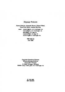
(a) numerical displays
(b) rotating arrows
(d) force and torque arrow with label
3
(c) transparent robot
(e) coordinate axes with label
Fig. 2. Interactive visual features.
2
Visual Features
This section presents five visual features for robot viewers. These features have three important properties in common. They are – intuitive, such that the displayed information is self-explanatory, – interactive, such that an interaction device (e.g. a computer mouse or touch screen) can be used to toggle between displayed parameters or switch the visualization mode, and – co-located, which means that these features provide information directly at the respective location to which the information belongs. The following subsections describe the visual features in detail. An exemplary implementation is detailed in Sect. 3. 2.1
Visualizing numerical parameters
Billboards are 3d objects that are always facing the camera of a virtual scene. In a robot viewer they are well suited for displaying numerical parameter values, such as joint angles or joint torques, as shown in Fig. 2(a). If they are placed in front of the respective joint, occlusions by the robot structure can be prevented, and furthermore they appear closer to the borders of the visualization window
4
Interactive Features for Robot Viewers
because of the perspective view on virtual scenes. Billboards can be equipped with an arrow to indicate their affiliation to the respective robot joint. Additionally, they may be semitransparent such that they do not obscure the robot. Intuitive interaction is enabled by toggling visibility of the billboards by mouse click on the robot structure or on the billboards. 2.2
Visualizing joint parameters
For visualizing joint accelerations or joint torques, this article suggests round arrows around the robot joints, see Fig. 2(b). These arrows are rotating with constant speed. By altering the arrows’ rotating direction and arrow width, the direction and magnitude of the respective joint parameter can be intuitively presented. They were originally designed to display the proximity to robot singularities [14]. For torque controlled robots it is especially useful to map the torque error of commanded and measured joint torques to the arrows, because first this difference indicates the direction and amount of acceleration of the robot joint, and second it helps detecting possible errors in the robotic system, either in the controller or the sensors. A mouse click onto an arrow will cause a billboard to appear showing the precise numerical values of the round arrow. 2.3
Visualizing target poses
Transparent robots doubles are well suited for visualizing target poses of robots, Fig. 2(c). In particular, when robots are driving to initial positions, their transparent counterparts can not only indicate their final configuration, but also anticipate the path robots will move. Through the transparency the actual robot position is not occluded. Parameter values of the transparent counterparts are visualized by the numerical displays described in previous subsection 2.1. 2.4
Visualizing interaction forces and torques
Arrows are a widespread utility and are used by most robot viewers to indicate the desired or measured forces, torques, or velocities. This article suggests smart arrows, which – like usual arrow – represent the direction and magnitude of a parameter, but in addition have interactive properties. As soon as they are clicked by an interaction device, a billboard appears that is showing the name and the numerical value of the respective parameter. This additional property upvalues traditional arrows, especially for those cases in which the exact parameter value is needed. 2.5
Visualizing coordinate axes
Similarly to force arrows, coordinate axes are part of many robot viewers, and are suggested here as smart axes. Smart axes are clickable and can show their names in a billboard. This functionality is especially useful when having complex robotic systems with dozens of degrees of freedom such as Justin (see Fig. 1), for which some axes have the same position but different orientation.
Interactive Features for Robot Viewers
3
5
Proof of Concept – The DLR SeRo-Viewer
The requirements for visualizing torque controlled robots and for direct humanmachine interaction demand more than the pure implementation of the introduced visual features. With rising complexity of robotic systems, it becomes quite costly and time consuming to include those visual features, implement a communication interface, and integrate the kinematics for each robot one wants to visualize. In this section we present the DLR SeRo-Viewer. It is a proof of concept viewer that combines extensive functionality and ease of use, while being as generic as required for visualizing all kind of robotic systems. The SeRo-Viewer is a pure visualization tool without robot simulation algorithms which emphasizes the generic approach of the concept. The main properties of the presented tool are: – – – – – – –
easy to implement new robot-scenes taking almost zero effort flexible communication interface via UDP or shared memory intuitive visual feedback (see Sect. 2) script based interface without need to compile plugins intuitive usage extensible platform independent (Linux, Windows, ...)
The software concept is currently implemented for the InstantPlayer [13] and based on the open X3D standard [12]. The intuitive usage of the viewer is builtin in the software concept by providing two components that may be interpreted as classes following the object oriented paradigm: One component providing a shared memory and UDP interface as communication gateway and the other creating a serial robot encapsulating several features that are introduced in Sect. 2. They can be instantiated in a virtual scene and interact with each other. This modularity fits with two essential features of the X3D standard: The definition of own objects that are encapsulated in so-called protos, and the routing concept, which allows routing signals from one X3D node to another. Each proto has a declaration part (see examplary Fig. 3) where the fields and datatypes of the user interface are defined, and an implementation part that contains the functionality of the proto (not shown here). Using different instances of a proto the scene description can be short and nevertheless include many features (see Fig. 7). These protos are loaded by the visualization toolkit (in our case the InstantPlayer), which also builds the specified scene graph and renders the 3d models. The next subsections introduce the two main components of the SeRo-Viewer: the SerialRobot proto in the next subsection and the communication concept in Sect. 3.2. At last, an example code for visualizing a light-weight robot is given showing a realization of a complete scene description in a few lines of code.
6
Interactive Features for Robot Viewers
PROTO SerialRobot [ # robot parameters : field SFString name " robot " field MFVec4f dhParams [0 ,0 ,0 ,0] field SFString directory " " field MFString filenames [ " " ] exposedField SFMatrix4f baseFrame 1 0 0 0 0 1 0 0 0 0 1 0 0 0 0 1 exposedField SFMatrix4f flangeFrame 1 0 0 0 0 1 0 0 0 0 1 0 0 0 0 1 exposedField MFFloat jointAngles [0] exposedField MFNode children [ ] eventOut SFMatrix4f f w d K i n F r o m B a s e T o F l a n g e # additional visualization features : exposedField SFBool e n a b l e T o u c h S e n s o r TRUE field MFVec3f o f f s e t s T o C e n t e r O f J o i n t s [0 ,0 ,0] exposedField SFBool showAxes FALSE field SFFloat axesSize 0.2 exposedField SFFloat a x e s T r a n s p a r e n c y 0 exposedField SFBool showArrows FALSE field SFFloat arrowRadius 0.1 field SFFloat ar ro w Wi dt h Sc al e 0.01 eventIn MFFloat torques exposedField SFBool sho wBillboa rds FALSE field SFFloat bi llboard Scale 0.05 eventIn MFFloat bi ll b oa rd V al ue s ]
Fig. 3. The SerialRobot proto.
3.1
Visualization
In the following, the concept of creating a serial robot providing several features is introduced. Fig. 3 shows the interface to the SerialRobot proto. With this interface the features contained in the proto (see Sect. 2) are customized to the current scene and parameterize the visualized robot. Due to the modular concept, the features can also be used without the encapsulation in the proto. The first design choice is the format of the scene graph to be built. There are two possibilities to include the kinematics of the robot: either by building a flat hierarchy, see Fig. 4(a), or by representing the kinematic structure in the scene graph, see Fig. 4(b). In a flat hierarchy each link i of the robot is child of the root node (i ∈ [0, N − 1], N is the total number of joints). Each pose of a link is calculated (represented by the node “forward kinematics” in the figure) and set accordingly. If a nested structure is chosen each link i is parent of the link i + 1 and the direct computation of the forward kinematics is avoided. In our concept, the flat hierarchy is chosen as it provides the user with the transformation from base joint to the flange, which is not directly available in a nested structure. Using this transformation as an output of the proto, it helps to overcome one problem of visualization tools independent of e.g. the robotic control, a simulator or a planner: the consistency between the scenes which now can easily be checked. The hierarchy is built as follows: For each name in filenames a transformation node (in the figure called “link”) is created and serves as a parent node. The 3d geometry data of the robot links are loaded from the specified filenames in the directory as children of that parent nodes. To provide the different features more children are created by instantiating the protos for coordinate axis, bill-
Interactive Features for Robot Viewers
root node
7
root node
foward kinematics
link 0 mesh link 0
...
link N
link 1
billboard
force arrow link 1
...
mesh
billboard
force arrow
(a) flat hierarchy
link N
(b) nested hierarchy
Fig. 4. Hierarchies of a scene graph.
boards, rotating arrows and the touch sensor. More features can be included by adding other children. In the node “forward kinematics” the forward kinematics given by the DH-Parameters is calculated and each resulting transformation matrix is routed to the respective link (see the dotted lines in Fig. 4(a)). As the kinematic of a robot starts at the location of the robot base in the world, this transformation can be set using the baseFrame. The transformation from the last joint to the flange of the robot can be specified with the flangeFrame. The eventOut fwdKinFromBaseToFlange returns the transformation from base to flange, such that the user has access to the calculated forward kinematics. Thus, a robotic tool can be simply added to the robot flange by routing that transformation to the tool’s location. There is an even simpler possibility of adding tools to the robot flange, namely by adding them as children to the robot. In both cases the added objects are moving according to the robot’s movements. To customize the features of the SerialRobot the according fields can be set if they vary from the initial values. The field offsetsToCenterOfJoints is used to move the display of the rotating arrows and billboards from the location defined by the dhParameters. Although the SerialRobot-proto is built for serial robots, parallel kinematics can be implemented using several robots with serial kinematics. 3.2
Communication
The SeRo-Viewer is designed to receive robot data from external programs or X3D nodes. This section introduces the concept of a UdpReceiver proto: It receives UDP-packets and generates X3D events that can be directly routed to the virtual robot. In order to cover most of the various requirements of external programs, numerous parameters can be set (see Fig. 5). The most important parameter structure defines the structure of the UDP-packets as string. Different
8
Interactive Features for Robot Viewers
PROTO UdpReceiver [ field SFString structure " " field SFInt32 udpport 0 field SFInt32 bufferOffset 0 field SFBool isDouble TRUE field SFBool columnMajor TRUE field SFBool o n l y L a t e s t P a c ke t TRUE field SFFloat scale 1.0 field SFInt32 debuglevel 1 eventOut SFBool receiving eventOut SFBool recei veTrigge r ]
Fig. 5. The UdpReceiver proto.
events are generated depending on the structure’s definition. The UdpReceiver proto supports events for values, vectors, and homogenous transformation matrices. The definition of the UDP-structure is not in the C-header style, for two main reasons. First, it is much more compact defining the structure as string inside an X3D file, and second many programs choose a format different to C when defining their UDP-structure, such as the well-known Matlab toolbox Simulink. Similarly to the UdpReceiver proto the SeRo-Viewer contains the ShmReader proto that communicates via shared memory, which has the advantage of reducing communication delays compared to UDP.
3.3
Example
With the two protos introduced in previous sections visualizing robots becomes quite easy. The following lines present an example for visualizing the DLR/KUKA light-weight robot (LWR) [15], which is equipped with position and torque sensors in each joint allowing the robot being operated impedance controlled. The code for visualizing the LWR as shown in Fig. 6 is listed below in Fig. 7.
Fig. 6. Visualization of the light-weight robot obtained with the example code.
Interactive Features for Robot Viewers
9
This code has ten important lines, five for specifying the properties of the LWR, three for defining the communication parameters, and two for routing the communication events to the LWR. These lines of code are sufficient for visualizing a robot that is moving according to the data of the UDP-packets and for using all the features of the SeRo-Viewer, which will be described in detail in the following section. The only precondition is having the geometry data of the robot links positioned and oriented according to Craig’s Denavit-Hartenberg notation [16], which means that the origin of each single joint is given such that its z-axis is coaxial with the rotational direction. # X3D V3 .0 utf8 Scene { EXTERNPROTO SerialRobot [] " P R O T O _ s e r i a l R o b o t . wrl " EXTERNPROTO UdpReceiver [] " P R O T O _ u d p R e c e i v e r . wrl " children [ DEF lwr SerialRobot { filenames [ " base . wrl " , " link1 . wrl " , " link2 . wrl " , " link3 . wrl " , ←" link4 . wrl " , " link5 . wrl " , " link6 . wrl " , " link7 . wrl " ] directory " 3 dModels / robots / lwr / wrl / " dhParams [ 0 0 0 0.31 , 1.5708 0 0 0 , -1.5708 0 0 0.4 , -1.5708 0 0 0 , ←1.5708 0 0 0.39 , 1.5708 0 0 0 , -1.5708 0 0 0 ] o f f s e t s T o C e n t e r O f J o i n t s [ 0 0 -0.2 , 0 0 0 , 0 0 -0.2 , 0 0 0 , 0 0 ←-0.2 , 0 0 0 , 0 0 0.1 ] } DEF udpProto UdpReceiver { structure " 7 F7F " udpport 32000 } # insert here other scene - elements ] ROUTE udpProto . values0 TO lwr . jointAngles ROUTE udpProto . values1 TO lwr . torques # insert here other routings }
Fig. 7. An X3D file for visualizing the light-weight robot.
4
Applications
The SeRo-Viewer can be used for visualizing various robots. This section presents five applications to different robots of our research institute. 4.1
Rollin’ Justin
DLR’s Rollin’ Justin is the combination of a humanoid upper body called Justin [17] and a mobile platform with a variable base [18]. Although the platform with its four wheels has a parallel kinematics, it can be visualized using the SerialRobot proto, see Fig. 1. The overall system has a total amount of 51 degrees of freedom (DoF) where the upper body has 43 DoF: five DoF for the torso and head, 14 DoF for both arms and 24 DoF for the two four-fingered DLR Hands II.
10
Interactive Features for Robot Viewers
(a) DLR bimanual haptic device
(b) DLR/HIT Hand II
(c) SpaceJustin
(d) DLR Biped Fig. 8. Applications
4.2
The DLR Bimanual Haptic Device
The DLR bimanual haptic device [19] is a haptic device consisting of two LWRs. It is used for interaction with haptic feedback with remote environments and virtual reality scenes. The user sits between the robots that are mounted behind him and which can be operated torque and position controlled. If they are position controlled the desired position should be visualized. If they are torque controlled, not only for security reasons, it is crucial to know which torque is applied at the moment. Activating the robot with high torque errors leads to a high acceleration of the robot and poses a risk for the user. Both requirements are met by using the SerialRobot proto. The visualization of the haptic device in torque mode is similar to the one shown in Fig. 8(c) or Fig. 1. In Fig. 8(a) the visualization in position mode is shown where the green transparent robot shows the commanded desired positions. The shift between both modes is toggled using the UdpReceiver proto.
Interactive Features for Robot Viewers
4.3
11
The DLR/HIT-Hand II
The DLR/HIT-Hand II is an anthropomorphic hand with five fingers [20] and 15 DoF. All fingers are equal having three degrees of freedom and three finger links where the last two links are coupled with a 1:1 ratio. The hand is visualized using five instances of the SerialRobot proto, one instance representing one finger. Especially the torque arrows are very useful while grasping and manipulating to display the current grasp forces. During grasp planning the object can be included in the scene as it is done e.g. in [21]. 4.4
SpaceJustin
DLR’s telepresence system consists of the bimanual haptic device (see Sect. 4.2) and a humanoid upper body (see Fig. 8(c)). SpaceJustin has three DoF for the torso and the head, seven DoF for each arm and 15 DoF for each hand, resulting in a 47 DoF robotic system. Monitoring commanded torques and positions intuitively in this complex system makes visualization mandatory. Axes labels clarify the use of different base and flange frames in the system. 4.5
The DLR Biped
Another application of the SerialRobot is the DLR Biped [22]. It is based on the technology of the torque controlled LWRs as they are used e.g. for the bimanual haptic device or Rollin’ Justin. Similar to the arms, each leg has seven DoF.
5
Conclusions And Future Work
Torque-controlled robots create new challenges for robot viewers, because they open new areas of application while having at the same time considerably more measured parameters. This article presented new intuitive, interactive and colocated visual features for such robots. Based on these features a proof of concept viewer, the SeRo-Viewer has been introduced. The SeRo-Viewer is a tool for visualizing robotic systems with focus on three key aspects: ease of use (clickable visual features), easy to implement (only couple of lines needed to code), and generic (arbitrary UDP and shared memory packages). Since the SeRo-Viewer follows the open X3D standard, all the functionality of available X3D viewers can be accessed, such as various stereo-visualization modes, augmented reality features, vision based tracking, humanoid animation, physics engines, and interfaces to dozens of interaction devices. Furthermore, X3D viewers can be extended by new protos or plugins, allowing to integrate new functionality easily. The presented SeRo-Viewer including the new visual features have already been proven to visualize five different robotic systems of our institute while intuitively presenting robotic data. Future developments will enhance the functionality and the interfaces of the introduced protos. Exemplarily alternative definitions to the DH-parameter specification for robot kinematics is planned to be integrated.
12
Interactive Features for Robot Viewers
Acknowledgment We would like to acknowledge the excellent support from the Fraunhofer Institute for Computer Graphics Research (IGD), specifically from Sabine Webel, Uli Bockholt and Johannes Behr.
References 1. Quigley, M., Conley, K., Gerkey, B.P., Faust, J., Foote, T., Leibs, J., Wheeler, R., Ng, A.Y.: ROS: an open-source robot operating system. In: IEEE Int. Conf. on Robotics and Automation (ICRA) Workshop on Open Source Software. (2009) 2. Diankov, R.: Automated Construction of Robotic Manipulation Programs. PhD thesis, Carnegie Mellon University, Robotics Institute (2010) 3. Miller, A., Allen, P., Santos, V., Valero-Cuevas, F.: From robot hands to human hands: A visualization and simulation engine for grasping research. Industrial Robot 32 (2005) 55–63 4. Hirukawa, H., Kanehiro, F., Kajita, S.: OpenHRP: Open architecture humanoid robotics platform. In Jarvis, R., Zelinsky, A., eds.: Robotics Research. Volume 6 of Springer Tracts in Advanced Robotics. Springer Berlin / Heidelberg (2003) 99–112 5. http://www.peekabot.org/: (2011) 6. ABB Robotics: Operating Manual RobotStudio, V¨ aster˚ as, Sweden. (2007) 7. KUKA Robotics Corporation: Robotic simulation (2006) white paper. 8. Freund, E., Hypki, A., Pensky, D.: New architecture for corporate integration of simulation and production control in industrial applications. In: Proc. of the IEEE Int. Conf. on Robotics and Automation (ICRA). (2001) 806 – 811 9. Brunner, B., Landzettel, K., Schreiber, G., Steinmetz, B., Hirzinger, G.: A universal task level ground control and programming system for space robot applications - the MARCO concept and it’s application to the ETS VII project. In: Proc. of the Int. Symp. on Artifical Intelligence, Robotics, and Automation in Space (iSAIRAS), Noordwijk, The Netherlands (1999) 10. Zacharias, F., Borst, C., Hirzinger, G.: Capturing robot workspace structure: representing robot capabilities. In: Proc. IEEE/RSJ Int. Conf. on Intelligent Robots and Systems (IROS), Nice, France (2007) 3229–3236 11. Bellmann, T.: Interactive simulations and advanced visualization with modelica. In Association, M., ed.: Proc. of the Int. Modelica Conference. Volume 7., Como, Italy, Linkping University Electronic Press (2009) 12. Brutzman, D., Daly, L.: X3D: extensible 3D graphics for Web authors. Morgan Kaufmann series in interactive 3D technology. Elsevier/Morgan Kaufmann (2007) 13. Behr, J., D¨ ahne, P., Jung, Y., Webel, S.: Beyond the web browser - X3D and immersive VR. In: Proc. of IEEE Symp. on 3D User Interfaces (3DUI), Charlotte, North Carolina, USA (2007) 14. Hulin, T., Schmirgel, V., Yechiam, E., Zimmermann, U., Preusche, C., P¨ ohler, G.: Evaluating exemplary training accelerators for programming-by-demonstration. In: Proc. IEEE Int. Symp. in Robot and Human Interactive Communication (Ro-Man), Viareggio, Italy (2010) 467–472 15. Hirzinger, G., Sporer, N., Schedl, M., Butterfaß, J., Grebenstein, M.: Torque-controlled lightweight arms and articulated hands: Do we reach technological limits now? The International Journal of Robotics Research 23 (2004) 331–340 16. Craig, J.J.: Introduction to Robotics Mechanics and Control. second edn. Addison-Wesley Publishing Company, Inc., USA (1989) 17. Borst, C., Ott, C., Wimb¨ ock, T., Brunner, B., Zacharias, F., B¨ auml, B., Hillenbrand, U., Haddadin, S., Albu-Sch¨ affer, A., Hirzinger, G.: A humanoid upper body system for two-handed manipulation. In: Proc. of the IEEE Int. Conf. on Robotics and Automation (ICRA). Volume 2. (2007) 2766–2767 18. Borst, C., Wimbock, T., Schmidt, F., Fuchs, M., Brunner, B., Zacharias, F., Giordano, P.R., Konietschke, R., Sepp, W., Fuchs, S., Rink, C., Albu-Sch¨ affer, A., Hirzinger, G.: Rollin’ justin - mobile platform with variable base. In: Proc. of the IEEE Int. Conf. on Robotics and Automation (ICRA). (2009) 1597 –1598 19. Hulin, T., Hertkorn, K., Kremer, P., Sch¨ atzle, S., Artigas, J., Sagardia, M., Zacharias, F., Preusche, C.: The DLR bimanual haptic device with optimized workspace. In: Proc. of the IEEE Int. Conf. on Robotics and Automation (ICRA), Shanghai, China (2011) 3441–3442 20. Liu, H., Meusel, P., Hirzinger, G., Jin, M., Liu, Y., Xie, Z.: The modular multisensory DLRHIT-Hand: Hardware and software architecture. IEEE/ASME Transactions on Mechatronics 13 (2008) 461–469 21. Roa, M.A., Hertkorn, K., Borst, C., Hirzinger, G.: Reachable independent contact regions for precision grasps. In: Proc. of the IEEE Int. Conf. on Robotics and Automation (ICRA), Shanghai, China (2011) 5337–5343 22. Ott, C., Baumg¨ artner, C., Mayr, J., Fuchs, M., Burger, R., Lee, D., Eiberger, O., Albu-Sch¨ affer, A., Grebenstein, M., Hirzinger, G.: Development of a biped robot with torque controlled joints. In: Proc. of the IEEE-RAS Int. Conf. on Humanoid Robots (Humanoids), Nashville, Tennessee, USE (2010) 167–173