INTERACTIVE LEARNING OF CONTROL CONCEPTS USING EASY JAVA SIMULATIONS J. Sánchez*, S. Dormido*, F. Esquembre**, R. Pastor* * Dpto. de Informática y Automática, UNED, Juan del Rosal 16, 28040 Madrid. Spain. E-mail:{jsanchez,sdormido}@dia.uned.es ** Dpto. de Matemáticas, Univ. de Murcia, Campus de Espinardo, 30071Murcia, Spain. E-mail:
[email protected] Abstract: This paper deals with the creation of interactive computer simulations that can be used as virtual laboratories in the field of control engineering education. We introduce EJS, a Java-based tool designed to help create interactive scientific simulations, which has been extended to provide support for authors in this field. Creating interactive simulations using EJS involves the following three steps: writing the mathematical model, building the graphical user interface (GUI), and linking the GUI elements to the model’s variables. Models of control engineering can be specified either using the programming support provided by EJS or by using Matlab/Simulink, which can then be controlled from EJS. We show two examples of how this second mechanism works. Copyright © 2004 IFAC. Keywords: Control education, interactivity, virtual laboratory, web-based education.
1. INTRODUCTION The classical approach to designing a control system using traditional tools can be considered a “noninteractive approach”. This is because it is not possible to know the consequences of the decisions taken during the design process, until we are close to the task’s end, just before the final hardware implementations. This situation forces us to repeat the same steps many times in order to tune the design parameters, making this a very time-consuming activity. This is a direct consequence of the fact that there is not a real-time link between the design and the analysis phases, preventing the designer from appreciating the gradient of change in the performance criteria given for the elements he/she is manipulating. Were there a real-time connection or link between the decisions taken during the design phase and the results
obtained in the analysis phase, we could mingle both phases in one (Dormido, 2003). In this new approach, the decisions taken in some steps would show on-thefly the differences between the simulation results and the original control specifications. But this proposed link to merge analysis and design can exist only if interactivity is considered as a cornerstone in the development of new software tools for control education. This new approach is known as interactive design. In such high-interactive system, several graphics windows, reflecting the value of every active element and the constraints among them, are constantly updated. Consequently, the control designer can appreciate the impact of his/her actions in the system’s behavior at a glimpse and from different perspectives. The designer can then identifies the bottlenecks of the designs in a very easy way and try to work them out.
But, and this is probably even more important, not just can he/she identify the effect of the manipulation of a displayed design parameter, but also its direction and amplitude become apparent. Examples of this new educational philosophy for teaching automatic control are described in (Cooper and Fina, 1999), (Piguet and Gillet, 1999), (Schmid, 1999), (Sánchez et al., 2002), and (Dormido and Esquembre, 2003). However, the construction of these interactive applications has two main drawbacks: programming skills and developing time. Indeed, a control engineering teacher knows how to use different modeling and simulation environments, but these tools are typically not oriented to the development of dynamic pictures from the perspective of interactive design. Making extensive use of interactivity with these tools would require a non-trivial effort. Therefore, it seems clear that the academic control community demands a tool to develop interactive modules (instructional simulations) with low programming cost, interactivity as the main feature, and an as small as possible economic cost. The paper is organized as follows. First, a software program called EJS is introduced as an appropriate tool for the creation of such interactive control applications. Next, we describe in detail the use of EJS in connection with Matlab/Simulink to develop two examples of interactive applications in the field of control engineering. 2. WHAT IS EJS? Easy Java Simulations, EJS for short, is an opensource (free from charge) tool developed in Java, specifically designed to help non-programmers to create scientific simulations (Esquembre, 2004). The user needs to provide, at a reasonable high-level, the analytical model, design the graphical view, and decide about the offered interactivity. EJS will then automatically generate the Java source, compile it into Java classes, pack the classes in a Jar file, and produce several HTML pages with the author-provided narrative and the ready-to-run applet for the simulation. The tool’s architecture derives from the model-viewcontrol (MVC) paradigm. The philosophy of this paradigm is that interactive simulations must be composed of three different parts:
- the representation of the phenomena in terms of variables and relationships among these variables (the model), - the graphical representation of the states of the phenomena (the view), and - the specifications of the user’s actions to perform on the simulation (the control). These three parts are deeply interconnected. The model obviously affects the view, since a change in the state of the model must be made graphically evident to the user. The control affects the model because control actions can (and usually do) modify the value of variables of the model. Finally, the view affects the model and the control, because the graphical interface can contain components that allow the user to modify variables or perform the predefined actions. In fact, going a step further in the process of simplifying the construction of a simulation, Ejs suppresses the control part, merging it half into the view, half into the model. According to this, EJS simulations are created by specifying a model for the simulated system and by building a view that continuously visualizes the state of this model and that readily responds to user interaction. In order to describe a simulation, an author needs to be able: 1. To define the model in three steps: (a) identify the set of variables that describe the system, (b) initialize these variables, and (c) describe the mathematical equations. 2. To construct a view that offers a schematic or realistic visualization of the phenomena. 3. To establish the appropriate user interaction with the model by establishing links between the graphical interface of the simulation and the response of the model to user-driven changes of it. 4. Optionally, to include textual information about the simulation (narrative). The model is what conveys the scientific part of the simulation and is thus the responsibility and the main interest of the target user. Control teachers are used to describing their algorithms in terms of mathematical equations and to translating these into algorithms of a computer language, or by means of high-level tools such as Matlab/Simulink. The main target when creating the model of a simulation is to concentrate in the analytical description of the phenomena, the content, and the accuracy of the simulation. However, the creation of the necessary graphical user interface (that is, the view) is the part of the simulation that demands more knowledge of advanced programming
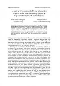
techniques. And, to make the situation even worse, the addition of interactivity to this interface involves mastering sophisticated software techniques (such as event-handling or multitasking), which requires a big investment of time and effort. EJS helps its users through all the process. With respect to the model, the tool provides extensive scaffolding to define it, while still retaining the flexibility of a general programming language so that it is possible to specify almost any type of algorithms. This is pedagogically important, since the process of learning good control fundamentals consists, to a great extent, in understanding the basic principles to build models EJS offers two ways of specifying the dynamics of the model. The first one is a built-in editor and solver for systems of ordinary differential equations (ODE). The user writes the equations in a way much similar to what he/she would write on a blackboard, and the system automatically generates the code that numerically solves the system using one of several of the provided standard algorithms (Figure 1). The system is also able to handle simple state-events for these ODE. The second facility is a connection to Matlab/Simulink that lets users design and solve their models with the help of these tools. In this last situation, the model is fully defined by a Simulink block diagram, and all that is necessary is a text file that informs EJS of the names of the Matlab/Simulink variables so that it can carry on the bidirectional linkage between view (Java-coded interactive interface) and the model (Simulink diagram) once the final application is generated.
Fig. 1. Edition panel to write the ODEs and select the solver. This feature is obviously useful for Matlab users who can then access and run their Matlab code from an EJS application. But also for those who have already developed a model using Simulink block diagrams. EJS can then be used as a tool to create the dynamic interactive user interface that is needed to turn this
simulation into an effective educational virtual laboratory (Figure 2). Detailed documentation on the creation of EJS simulations and the examples presented here can be found in http://fem.um.es/ejs/. Model
View
+ Simulation
JMatLink.class
Matlabfiles Simulinkmodels
Fig. 2. Building a simulation with Ejs and Simulink. To create the view, EJS provides a set of advanced graphical elements (Figure 3) created using both standard Java Swing components (containers, buttons, text fields, sliders, combo boxes,…) and on specific scientific two- and three-dimensional visualization classes from the Open Source Physics project (Christian, 2003) (particles, vectors, images, vector and scalar fields,…). These elements are used in a simple drag-and-drop way to build the interface. The user needs to design the view so that it will offer a visualization of the phenomenon appropriate to the desired pedagogical goals. In particular, the view should encourage students to explore the phenomenon under different engineering perspectives in order to gain better insights of the system.
Fig. 3. Library of graphical elements of EJS. To complete the view, its different elements have to be instructed to display on the screen according to the values of the variables of the model. Every graphic element of EJS has internal values, called properties, that can be customized to make the element look and behave in a certain way (change its displayed value,
position, size, etc). From this, the user can connect the properties of the graphical elements of the view to the value of the different model’s variables. Some of these properties can also be instructed to trigger userdefined actions (typically routines defined in the model) when the user interactively changes them. This procedure, which we call linking the model and the view, is what turns the simulation into a real dynamic, interactive application. This mechanism makes up a simple, though very effective, way of building advanced interactive user interfaces. The reason for this is that linking is a two-way connection. When one or more variables of the model change, this change is passed on to the view so that it immediately displays the new state of the model. In return, because the elements provided have built-in interactive capabilities, any interaction of the student with the interface immediately affects the model variables that have a connection to it. For example, let us imagine an EJS simulation of the control of a magnetic levitator. The magnets are represented in the view by means of rectangles with two colors to represent the two polarities. If the dimension of a magnet is modified by dragging and stretching with the mouse the corners of the rectangle, the variable representing the magnet mass in the analytical model will immediately reflect this change (thus affecting the dynamic of the system). With all this high-level information, which only the user can provide, EJS takes care of all the low-level procedures needed to create the final simulation. It will generate the Java code that handles all the internal tasks, compile it into Java classes, pack the classes in a compressed file, and end up with a ready-to-use simulation. Simulations created using just EJS can be used as stand-alone applications under different operating systems (for instance, a .BAT file is provided when running under Windows), or be distributed via Internet and run as applets within HTML pages (which are also generated by EJS) by using any Java-enabled web browser. The tool also includes a simple HTML editor to help the teacher enhance the generated web pages with pedagogical information and/or instructions for the simulation. 3. A FIRST EXAMPLE: THE SIMPLE PENDULUM In this first example, a simulation of a well-know dynamical system is presented. It consists of a twodimensional pendulum made of a bob of fixed mass that is suspended from a rod (of negligible mass) under the action of gravity. The differential equation that models the simple pendulum with friction is:
m ⋅ l ⋅ && x + c ⋅ l ⋅ x& + m ⋅ g ⋅ sin( x) = 0
(1)
Figure 4 shows the view and control that we created for this application using EJS and that allows the user full interaction with the simulated pendulum. It can be appreciated, at a first glance, that there are different elements in the view to run the simulation and change the relevant parameters of the system (mass, gravity, friction coefficient, integration step). In addition, the graphical representation of the pendulum is highly interactive as well, since it is possible to modify the rod length, the initial angular position and velocity just by dragging the bob or the velocity vector.
Fig. 4. View of the EJS application. The model for this simulation was taken from an existing Matlab/Simulink example. Small changes were needed to the original block diagram before it could be used by EJS. These modifications are necessary for sending/receiving the value of some of its variables and parameters to/from Matlab’s workspace, which are actually what EJS accesses. Figure 5 shows the block diagram as used by EJS. This block diagram corresponds to the model of the simple pendulum in equation 1. The main steps to use a traditional Simulink block diagram within EJS are three. The first one consists,as we already mentioned, in doing some changes to the original Simulink model. These changes are necessary because Simulink models are, obviously, created to be run within Simulink. Because the communication between Simulink and EJS will take place through Matlab’s workspace, the first change we need to do to the Simulink model is that it sends/receives the value of some of its variables and parameters to/from Matlab’s workspace. The second change derives from the fact that Simulink models are usually played and paused by the user through Simulink’s user interface, that is, the commands of the menubar. Hence, the model must be changed so that it stops after every integration step.
This is simply done by including in the model diagram one “Matlab function” block with the Matlab command “set_param (gcs, 'SimulationCommand', 'Pause')”. This way, EJS can control exactly when the model needs to play. With respect to the first change, we can appreciate in the block diagram of Figure 5 that some system
parameters have been adapted to be read from Matlab’s workspace: rod length, bob mass, gravity, friction, initial angular position and velocity, integration step. Also, the block diagram has been slightly modified so that it writes the simulation state in the Matlab’s workspace (time, position, and velocity) after every integration step.
Fig. 5. Simulink block diagram. The reading of the values of the Matlab’s workspace variables is done by including “Matlab function” blocks into the diagram to evaluate variables and/or expressions. Figure 6 shows the Simulink block in which the Matlab variable “mass” is evaluated to obtain the value of the mass of the bob and use it in the simulation.
Fig. 6. Source block to read a Matlab variable.
To write the model state into the Matlab’s workspace in each integration step is necessary to include as many “To workspace” blocks in the diagram as variables has the state vector of the model. As an example, Figure 7 shows the Simulink block used to send the angular position of the pendulum to the workspace.
Fig. 7. Sink block to send a state variable to the Matlab workspace.
The second step required to connect Simulink and EJS is the creation of a simple text file to inform EJS about the name of the Simulink model and the variables and parameters that will be accessible through Matlab’s workspace in order to interact with them from EJS’ interface. Figure 8 shows an excerpt of the text file pendulum.m designed for this example. teta; %EJS Variable InputOnly position; %EJS Variable OutputOnly omega; %EJS Variable InputOnly Velocity; %EJS Variable OutputOnly mass; %EJS Variable InputOnly length; %EJS Variable InputOnly gravity; %EJS Variable InputOnly friction; %EJS Variable InputOnly time; %EJS Variable OutputOnly dt; %EJS Parameter=maxstep InputOnly model='pendulum_model.mdl'; %Ejs Model
Fig. 8. Text file used to connect Simulink and EJS. The syntax for this text file is rather simple. What actually enables EJS to read and access these Matlab variables is the special comment at the end of the line which starts with the keyword ‘%Ejs’. This keyword must be followed by one of the following words: - Model. Indicating the name of the Simulink file. - Variable. This tells EJS that this is a regular variable of the Simulink model. - Parameter. Parameters are special variables defined inside Simulink blocks. Once the text file associated to the modified Simulink model is written, we are readyfor the third and final step, connecting the variables defined in EJS with the variables of the Matlab’s workspace (that will in turn be associated to variables/parameters of the Simulink model). Figure 9 shows EJS’ variables and how they are connected to Matlab’s variables.
To establish the connection between EJS and Matlab/Simulink, it is necessary to open a page of external variables in the EJS application (Figure 9). In this page we must introduce in the “External File” textfield the path to the text file created previously to store the names and types of the Matlab’s workspace variables and the name of the Simulink model. Now, whenever you create an EJS variable and right-click on it, you will be given a window with a list of the Matlab variables to which you can connect your EJS variable. By clicking on any of these variables the connection between your EJS variable and the Matlab variable will be established. Establishing a connection means exactly that: a) the value of the EJS variable will be pushed to the variable of the model before running Simulink, and that, b) the EJS variable will be given back whatever value the Simulink variable has after the model has run one integration step. After this preparatory work, running the Simulink model is done by including the Java command _external.step(1) in one of EJS’ evolution pages (Figure 10). A call to this method has the following effects: 1. The value of all EJS variables which are connected to a Matlab variable (except those declared as OutputOnly) is pushed to the Simulink model. 2. The Simulink model is run exactly one integration step. 3. The value of all Matlab variables which are connected to EJS variables (except those declared as InputOnly) are retrieved from the Simulink model.
Fig. 10. Evolution page of EJS to run an external model in Matlab/Simulink. Fig. 9. EJS page to connect external variables.
Once this process is completed, we can create the graphical view of the application in the standard
simple way provided by EJS. This includes linking the EJS model variables to the so-called properties of the graphical elements. This establishes in particular the interactivity for the simulation. Figure 11 shows a partial display of the tree-like structure of the pendulum view. The EJS graphical components used to build this view include panels, buttons, sliders, check boxes, and special drawing panels that host the actual primitive elements that display the pendulum: a line for the rod, a circle for the bob, and an arrow for the velocity vector. The creation of a view is done using a simple click-anddrop mechanism.
Fig. 12. Properties for the bob.
Fig. 13. Java method to calculate the angular position. 4. AN EXAMPLE OF DECENTRALIZED CONTROL
Fig. 11. Tree-like structure of the view. As an example of linking graphical elements and variables and actions in EJS, Figure 12 shows how the X and Y properties of the bob are connected to the computed x and y model variables. Also, the On Drag property is connected to the user-defined action newAngle(). This way, when the model changes the values of x and y, the position of the bob is automatically updated. But reciprocally, if the user drags the bob to a new (X,Y) position, the newAngle() method will be called and the new angular position will be calculated and sent to the Matlab’s workspace (theta variable) and, from it, to the Simulink model (Figure 13).
In this second example, we present an EJS application that explains the use of a completely decentralized control system as a mechanism for directly exploiting SISO methods in a MIMO setting. This approach considers that interactions can be treated as a form of disturbances. For example, if the first output, y1(t) of a m x m MIMO plant is described as: m
Y1 ( s ) = G11 ( s )U1 ( s ) + ∑ G1i ( s )U i ( s )
(2)
i=2
then the contribution of each input, other than u1, could be considered as an output disturbance G1i(s)U(s) for the first SISO loop. Whereas this approach is incorrect from a formal point of view, under certain conditions it can produce acceptable results. In the example, we will use a conventional multi-loop control scheme consisting of a 2x2 process and two feedback controller (Goodwin et al., 2001). Four transfer functions of the two-input, two-output plant are necessary to completely characterize the process dynamics:
G ( s ) G12 ( s ) G( s ) = 11 G21 ( s ) G22 ( s ) k 2 G11 ( s) = 2 G12 ( s) = 12 s +1 s + 3s + 2 k21 6 G21 ( s) = 2 G22 ( s) = 2 s + 2s + 1 s + 5s + 6
(3)
(4) (5)
where the coefficients k12 and k21 depend on the operating point and can determine the stability of each individual control loop when the other loop is opened. The transfer functions of the two feedback controllers C1(s) and C2(s) are:
C1 ( s) =
4.5( s 2 + 3s + 2) s( s + 4)
(6)
1.5( s 2 + 5s + 5) C2 ( s ) = s ( s + 4)
Another aspect to be taken into account in a decentralized approach is the important practical problem of how the controlled variables Yi and the manipulated variables Ui should be paired in the multiloop control scheme. A correct pairing is crucial since an incorrect configuration can result in poor control system performance and reduced stability margins. In the 2x2 control system example, there are two possible control configurations. In the first one, Y1 is controlled by adjusting U1, while U2 is used to control Y2. This configuration is referred to as the 1-1/2-2 control scheme. The alternative strategy is to pair Y1- U2 and Y2 -U1, configuration termed as 1-2/2-1. The method to be used to suggest pairings is the RGA (Relative Gain Array) developed by Bristol (Bristol, 1966). This approach requires only steady-state information and provides two important items of information: a measure of the process interactions, and a recommendation concerning the most effective pairing of controlled and manipulated variables. A detailed explanation of the calculation of the RGA can be found in (Sebor et al., 1988). In our example, and considering the system presented in Equation 2, the RGA obtained is: 1 1 − λ 1 − k12 k21 Λ= = λ − k12 k21 1 − λ 1 − k12 k21 λ
− k12 k21 1 − k12 k21 1 1 − k12 k21
(7)
To gain further insight into the stability problem, it is necessary to calculate the characteristic equation of both control schemes: 1-1/2-2 and 1-2/2-1. The transfer function of closed-loop system can be organized in matrix form as: Y1 ( s ) R1 ( s ) −1 = ( I + G( s)C( s ) ) G( s)C( s ) R2 ( s) Y2 ( s ) 0 C ( s ) C( s ) = 1 C2 ( s ) 0
(8)
where G(s) changes according to the pairing. Thus, for the 1-1/2-2 configuration G(s) is the same as in Equation 3 but in the 1-2/2-1 control scheme, G(s) is: G ( s ) G11 ( s ) G( s ) = 12 G22 ( s ) G21 ( s )
(9)
This way, we easily obtain the characteristic polynomial ds(s) of both configurations. Clearly, the development of an interactive application using this MIMO plant (or others) with two SISO controllers will allow us to change the operating points on-the-fly and measure the process interactions between loops and how sensible is to modify the pairing. After this brief discussion on the theoretical background of the application, the first step to start the design of an EJS application using Simulink is to define the block diagram. In this example, the block diagram modeling of the system, already adapted for EJS use, is shown in Figure 13. The variables to be read from the workspace are the references (variables r1 and r2) and the disturbances (variables disturb1 and disturb2). The information sent back to the workspace is composed of the plant outputs (variables y1 and y2), the two control actions (u1 and u2), the two error signals (error1 and error2), and the time (variable time). Notice that the block diagram is adapted to pair inputs and outputs by means of four switch blocks controlled by a variable named pairing. Therefore, modifying the value of this variable in EJS changes the structure of the system, and the pairing of inputs and outputs is made. Also, the block diagram has been modified to open or close the loops from the workspace by changing the value of the variables open1 and open2.
Fig. 14. Simulink diagram. The second step is to create the associated informative plain text file (see Figure 14) and the third is to connect Matlab’s variables with EJS’ variables. model='mimo_model.mdl'; %EJS Model %EJS Variable OutputOnly u1; %EJS Variable OutputOnly y1; error1; %EJS Variable OutputOnly %EJS Variable OutputOnly time; %EJS Variable InputOnly ref1; %EJS Variable InputOnly pairing; %EJS Variable InputOnly open1; disturb1; %EJS Variable InputOnly %EJS Variable InputOnly disturb2; %EJS Parameter=Plant/G12:Numerator k12; %EJS Parameter=Plant/G21:Numerator k21;
Fig. 15. Excerpt of the text file. The view of the final EJS application is shown in Figure 9. It is composed of several windows that provide a complete control of the decentralized control system. The main window (upper-left corner) allows users to run the simulation, change the value of some
variables, open and close information panels, choose the type of control in each loop (automatic or manual), and pair inputs/outputs according to the information of the RGA panel (lower-right corner). The four signal scopes of the plot panel (lower-left corner) lets users appreciate the effects of interactions in the two control loops with the SISO design. The relevant detail of the control parameter panel is the possibility of interactively changing the values of k12 and k21 just by dragging with the mouse the red dot in the diagram. Obviously, any change in either the k’s or the pairing will produce changes in the stability of the system, and this will be shown in the characteristic polynomial roots panel of the closed-loop system. Thus, all these panels visualize on-the-fly how sensible it is to pair the inputs with the outputs in function of the k’s values and under which conditions the closed-loop system is stable.
Fig. 15. Full view of the EJS application. In addition, the application allows us to study some robustness issues in decentralized control using a diagonal nominal model. In this case, Matlab is instructed by EJS to draw the picture of the singular values of the system (middle-right window in Figure 9). This is possible thanks to the evaluation of a userdefined Java method every time that a k variable is modified in the view. This method includes a Java statement _external.eval() for evaluating an Mfile that has all the Matlab sentences required to plot the singular value response of a continuous-time system. Every change of value of a k will then produce an immediate update of the Matlab picture. This example shows how all of Matlab’s graphic capabilities can also be used interactively from EJS. 5. CONCLUSIONS Easy Java Simulations is a tool that can be considered as a first step in the development of further and more advanced tools intended for control engineering educators with just some knowledge of programming, not for advanced programmers with little knowledge of control and modelling. Hence, EJS provides a conceptual structure and simplified tools that allow us
to concentrate most of our time in the description of the model of the system under consideration. To further support control engineering educators, EJS can also be used in conjunction with Matlab/Simulink. Then, according to the model-view-control paradigm, EJS facilitates the creation of the view and control, and Matlab/Simulink let control teachers develop the model using a language they already know. 7. ACKNOWLEDGMENTS Authors would like to acknowledge CICYT (grant DPI 2001-1012) and the Fundación Séneca, Murcia, Spain, for partially funding this work. REFERENCES Dormido, S. (2003). “The role of Interactivity in Control Learning”, 6th IFAC Symposium on Advances in Control Education (ACE 2003), Oulu (Finland). Juha Linfords (ed.), Elsevier, pp. 11-22. Cooper, D.; Fina, D. (1999). “Training simulators enhance process control education”, Proceedings of the American Control Conference, San Diego, CA (EE.UU), pp. 997-1001.
Piguet, Y.; Gillet, D. (1999). “Java-based remote experimentation for control algorithms prototyping”, Proceedings of the American Control Conference, San Diego, CA (EE.UU.), pp. 1465-1469. Schmid. C. (1999). “A Remote laboratory using virtual reality on the Web”, Simulation, 71, nº 1, pp. 13-21. Sánchez, J.; Morilla, F.; Dormido, S.; Aranda, J.; Ruipérez, P. (2002). “Virtual control lab using Java and Matlab: A qualitative approach”, IEEE Control Systems Magazine, 22, nº 2, pp. 8-20. Dormido, S., Esquembre, F. (2003). “The QuadrupleTank Process: An Interactive Tool for Control Education”, Proceedings of the European Control Conference, Cambridge, UK. Esquembre, E. (2004). “Easy Java Simulations: A software tool to create scientific simulations in Java”, Comp. Phys. Comm.vol 156, pp. 199-204. Christian, W. The Open Source Physics Project. http://www.opensourcephysics.org. Goodwin, C.G.; Graebe, S.F.; Salgado, M.E. (2001). Control System Design, Upper Saddle River, NJ: Prentice Hall. Bristol, E.H. (1966). “On a New Measure of Interactions for Multivariable Process Control”, IEEE Transactions on Automatic Control, 11, nº 1, pp. 133-134. Seborg, D.E.; Edgar T.F.; Mellichamp, D.A. (1988). Process Dynamics and Control, New York, PHI: John Wiley & Sons.