Interactive Media Server with Media Synchronized RAID Storage System Seung-Ho Lim
Yo-Won Jeong
Kyu-Ho Park
Computer Engineering Research Lab. EECS, Korea Advanced Institute of Science and Technology
Computer Engineering Research Lab. EECS, Korea Advanced Institute of Science and Technology
Computer Engineering Research Lab. EECS, Korea Advanced Institute of Science and Technology
[email protected]
[email protected]
[email protected]
ABSTRACT
On-demand interactivity means that users can freely interact with the media server by means of VCR like controls such as stop, pause, fast-forward or rewind. Given the extremely large data size of video, the high data retrieval bandwidth is required to support the interactivity to many users. In addition, the different resolution (X1, X2 and X4) of each interactive operation should meet each real-time IO requirements. In general, disk array technology is employed in video server to provide the high disk bandwidth and satisfy realtime IO requirements [5][12][11][13]. In constructing and managing media server with disk array, disk striping is very important configuration method. Disk striping is done by dividing the video data into blocks according to their presentation order and storing these blocks into different disks. While storing these blocks into different disks, the proper placement algorithm should be considered in disk array to efficiently support the retrieval of such streams at different interactivity for several reasons. First, each video blocks should be stored into disks to reduce the seek and rotational latency while minimizing the number of disk requests. Second, adjacent blocks supporting the interactive operations which are retrieved in same real-time playback round at the different interactive levels are stored closely in the disks to enhance the utilization of disk bandwidth. Third, special encoding techniques are required to easily support and manage the proper placement algorithm. In this paper, we propose an efficient placement algorithm to support the interactivity in media server, and develope the adaptive pre-fetching algorithm considering the interactive operation in our placement algorithm. Our placement policy is incorporated with an special encoder having the proposed bitcount control scheme, called F ine T uning of T ail Amount, that repeatedly tunes quantization parameters to adjust the bitcounts of video frames. This encoder can generate coded frames whose sizes are synchronized with the RAID stripe size, so that when various fast-forward levels are accessed we can reduce the seek and rotational latency and enhance the disk throughput of each disk in the RAID system. The rest of the paper is organized as follows. In Section 2, we present background and related works. In Section 3 we present the efficient placement algorithm and the adaptive pre-fetching algorithm. The proposed encoding technique is presented in Section 4. In Section 5, we present performance
We propose an efficient placement algorithm and per-disk prefetching method to effectively support interactive operations in the media server. Our placement policy is incorporated with an encoder having a special bitcount control scheme that repeatedly tunes quantization parameters to adjust the bitcounts of video frames. This encoder can generate coded frames whose sizes are synchronized with the RAID stripe size, so that when various fast-forward levels are accessed we can reduce the seek and rotational latency and enhance the disk throughput of each disk in the RAID system. In the experimental results, the proposed placement policy and bitrate control scheme can significantly improve the average service time, which can enlarge the capacity of the interactive media server.
Categories and Subject Descriptors D.4.2 [Operating Systems]: Storage Management; I.4.2 [Image Processing and Computer Vision]: Compression(Coding)
General Terms Algorithms, Management
Keywords Interactive Media Server, Disk Array, Stripe Size, Video Rate, Bit Count Control
1.
INTRODUCTION
Recent growth of Internet and multimedia technologies has created an infrastructure in which computer systems supported a wide range of on-demanding interactive multimedia services for education and entertainment business.
Permission to make digital or hard copies of all or part of this work for personal or classroom use is granted without fee provided that copies are not made or distributed for profit or commercial advantage and that copies bear this notice and the full citation on the first page. To copy otherwise, to republish, to post on servers or to redistribute to lists, requires prior specific permission and/or a fee. NOSSDAV’05 June 13–14, 2005, Stevenson, Washington, USA. Copyright 2005 ACM 1-58113-987-X/05/0006 ...$5.00.
177
results of our placement algorithm and encoding technique. Finally, we conclude in Section 6.
Disk No.
1
2
3
4
5
6
7
2.
Video i
I I I I
I I I I
BB BB BB BB
P P P P
BB BB BB BB
P P P P
BB BB BB BB
Video j
P P P P
BB BB BB BB
I I I I
I I I I
BB BB BB BB
P P P P
BB BB BB BB
RELATED WORKS
There are several previous works for designing the interactive media server. Among these, we describe the feasible works which are related to our proposed media server design. Rangaswami et al [10] developed the interactive media proxy that transforms non interactive broadcast or multicast streams into interactive ones. They carefully manage disk device by considering disk geometry for allocation and making several stream files according to the fast-forward levels. However this method consumes high storage capacity, and did not consider disk array. Disk array based works are as follows. X. Huang [4] studied the rate staggering method for scalable video in a disk array based video server. Rate staggering method stores the different rates of video data separately to provide efficient resolutions of videos. This method can reduce the buffer space and achieve better load balancing due to finer scheduling granularity. However, their allocation method did not consider the precise disk stirpe management and scalable encoding technique so that rate staggering method hardly apply to the real disk array. In addition, the finer granularity has the possibility to make more disk requests and reduce disk throughput. Shenoy [13] used the disk array to support the interactive operations in multi-resolution video. They present an encoding technique combined with placement algorithm to efficiently support interactive scan operation. In placement algorithm, they used two method, fixed-size and variable-size blocks allocation. Fixed-size block placement could make additional disk requests to retrieve video stream in one real-time playback round. Variable-size block placement can reduce additional disk requests however variable block management is very difficult in disk array. The placement algorithm and combined encoding technique presented in this paper can enhance the performance of the disk array based interactive media server both constructing and managing disk array. Actually, we have set up real interactive media server using SCSI disk array and linux operating system. The proposed placement algorithm, prefetching method, and encoding technique are implemented in linux operating system.
3.
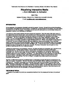
Figure 1: Proposed Placement Algorithm for Interactive Media Server on Disk Array. Let the GOP structure be fIBBPBBPBBg
of the useful data read to the total data read from disk array and guarantee more client’s continuous playback. When server employs disk array to store the video streams, the server interleaves the storage of each video stream among disks in the array to effectively utilize the disk bandwidth. The amount of data interleaved on a single disk, denoted as stripe size, is fixed when the disk array is configured. In that environment, an efficient placement policy to minimize the seek and rotational latency incurred by the servicing requests is as follows. First, the video streams are stored such that the same types of frame accessed during a round are in the same disks. Second, the different types of frame accessed in the same round are stored in adjacent to other disks. However, the video streams made from conventional encoding techniques don’t have fixed frame size which is opposite to the fixed stripe size; Some frames are over the stripe size and some frames are under the stripe size. It causes the additional disk requests when video frames are retrieved from disks at different fast-forward levels because frames are spread over more disks. Therefore, the special encoding technique is required to apply our placement policy. The encoding technique to make fixed size frames will be described in next section. In this section, we assume that the video streams are encoded with our encoding method. To precisely describe the proposed placement policy, let us assume that the size of encoded P-frame is same as stripe size. B-frame is smaller than P-frame and I-frame is larger than P-frame according to the dependence between frames. Therefore our encoding technique can make the size of Bframe be half of that of P-frame and the size of I-frame be twice as that of P-frame. As explained previously, our placement policy is that same types of frame are stored in the same disks and different types of frame are stored in the other disks. The GOP {IBBPBBPBB} is stored as follows. The I-frame consumes two consecutive stripes, P-frame consumes one stripe, and two B-frames consumes one stripe on disk array. The next GOP is stored in next stripe level on disk array, and so on. The Figure 1 shows the placement method when the encoded frames are described above. Using this method, we can minimize the number of disk requests for each fast-forward level. At normal playback, the server should be retrieved from all disk array with evenly distributed number of frames. For K-times speed-up fastforward, the server can skip every K-th disk to play out the video streams because the required frames to play fastforward are separated beyond the disk boundaries. Also, for
EFFICIENT PLACEMENT FOR INTERACTIVE OPERATION
3.1 Placement Policy on Disk Array In general, video stream consists of m GOP(Group of Picture)s, each GOP has n frames. For example, MPEG stream is represented as a sequence of I-, P-, and B-frames. To support K-times speed-up fast-forward, the system displays one out of every K frames. Let the structure of one GOP in encoded MPEG video be {IBBPBBPBB}. The next possible frame sequence of fast-forward scan could be {IPPIPP..} which is not include any B-frames, and the next one is {II..} without any P-frames, and so on. During each real-time playback round, the server should retrieve the fixed number of video frames for each client’s fast-forward level to ensure the continuous playback. In other words, each sub-sequence for each fast-forward level accessed during a round is required to retrieve together from disks to enhance the ratio
178
File System
File System
mis−prefetched data
Per−Disk Buffers
Conventional Buffers
I
I
BB
P
BB
P
I
I
I P
...
I P
RAID Device Driver
I
I
BB
P
I P
I P
I
I
...
I
...
RAID Device Driver
BB
P
BB
I
(a) Conventional prefetching Requests
I
BB
P
BB
P
BB
(b) Proposed Per-Disk Prefetching Requests
; ; ; ; ;; ;;;;;
Figure 2: Per-Disk Prefetching and Buffer Management; An Example of X2 fast-forward. The light gray and dark gray represents well-prefetched data mis-prefetched data, respectively. the different videos, the starting disk is also interleaves for the balancing of disk requests as shown in Figure 1.
Frame Size (Multiple of Stripe Size)
Dummy Data
3.2 Per-Disk Prefetching Method In general system, when the server retrieves data from disks, consecutive frames are retrieved ahead with the currently requested frames to increase disk throughput because prefetch requests are attached to the current requests and send to the disk. We call these frames are prefetch frames or requests to differentiate from the currently requested frames. However, the prefetch requests incur more data transfer time in disk and buffer space requirements in memory. Therefore, it is important that proper amount of frames are retrieved ahead at proper real-time playback time. The file system, which uses RAID storage, logically stores video files in sequential manner. The RAID storage physically interleaves the data across the disks as described before. It makes the different view point between file system’s logical address and RAID storage’s physical address, and file system does not know where the data is stored in disks physically. In this case, the prefetch requests are generated across disk array, as shown in Figure 2(a) because file system only know about the logically continuous allocation of video files and multimedia requests are large sequential accesses [2]. However, fast-forward plays split the disk request into several ones because they need only some portion of frames. It causes prefetching requests make unnecessary data retrieval for fast-forward plays. For example, when the server displays X2 fast-forward level, it retrieves the GOPs without any B-frames. However, the B-frames can be retrieve from disks by the prefetching requests. This would be overhead in both disk bandwidth and buffer space. To reduce the overhead owing to the unnecessary portion of prefetch requests, we propose the generation of prefetch requests for per disk, as shown in Figure 2(b). When current request are retreived from one disk, our file system generates the prefetch requests to retrieve more data from the same disk not other disks. We call this method per-disk prefetch method. Because our placement policy separates the frame types to other disks, the per-disk prefetch requests does not generates any unnecessary requests. Also, this increases the disk throughput by generating larger requests than that of conventional method at each disk. In summary, per-disk prefetch method can increase the disk throughput by gener-
x2
Cut Coded Data
x1
x0.5
I B B P B B P B B P B B I B B P B B ...
Frame Type
Figure 3: An Example of Distribution for padded dummy data and cut coded data
ating large size of disk request for each disk while reducing the number of additional disk requests at fast-forward interactive operations.
4. ACCURATE BIT COUNT CONTROL 4.1 Conventional Related Works In order to establish the placement policy described above, the bitcounts of all I-frames, all P-frames and all B-frames must be twice, same and half as strip size, respectively. For this, we can employ the CBR (constant bitrate) encoding using a video rate control scheme. The objective of the conventional video rate control is to enable a video source to generate its output rate under the constraints of a given constant bitrate, encoding buffer, and other factors related to the human visual system. Several previous studies have focused on these video rate control algorithms. Some schemes use dynamic programming [9] or Lagrangian techniques [3][8] to find optimal solution. Tiwari and Viscito [14] proposed a scheme based on a model for the picture complexity using the coding results of the randomly pre-selected macroblocks. In [6], the linear relationship between the actual bitcount and the codeword count was used for an accurate bit-rate control. These schemes was based on some kind of bitrate estimation models and tried to enhance the subjective video quality [7]. The output bitrate generated by these video rate control schemes is similar to given target bitrate in the average sense. However, bitcounts of each frame cannot be equal to given target bitcounts, because of modeling errors occur-
179
Rate control
19 14 9 4
QPs Input Frame
Motion estimation / compensation
DCT
Stored for next frame
Quantization IDCT
Encoded Frame
VLC
Inverse Quantization
18 13 8 3
17 12 7 2
16 11 6 1
15 10 5 0
Macroblock
Figure 6: An Example of assigning address of each MB of the frame having 5-by-4 MBs
Figure 4: Conventional MPEG-2 video encoder using a rate control
START
R-QVLC Input Frame
Motion estimation / compensation
DCT
Stored for next frame
Updated QPs
Adjust QPs
Quantization
IDCT
Compare VLC
N
Encoded Frame
Initial Stage starts
Fine-Tuning Stage starts N
Y BP=0; TRP=M-1; BN=1;
Inverse Quantization
Q[BP]++; BP + =BN;
BN==1
QVLC;
Y MK[BP-1]=NDQ N
Rate-Increasing Stage starts
Figure 5: The conceptual procedure of the R-QVLC scheme.
N
ABTB Y BN*=2
N
BN=BN/2
BN=BN/2 Q[BP~BP + BN - 1]--; BP + =BN;
AB!=TB
Q[BP~BP + BN - 1]++; BP + =BN;
3
Y 2
N
QVLC;
AB