Interconnecting Unstructured P2P File Sharing Networks Jaime Lloret Department of Communications, Polytechnic University of Valencia Camino de Vera s/n 46020 Valencia (Spain) Phone: +34 609549043 Fax: +34 962849313
[email protected] Abstract Currently there are a lot of public P2P file sharing networks in existence. Some of them have millions of users. There is a need for a system that can search and download from every P2P network. This article describes a novel structured interconnection system that works over multiple unstructured P2P file sharing networks and provides additional management features. This system works across different P2P system architectures. It is scalable and fault-tolerant. It also provides a global interconnection system.
Keywords: P2P file-sharing, Interconnection system, Overlay networks, P2P architecture. 1
Introduction
The number of users connected to public P2P Networks is increasing daily. Today, there are a great variety of P2P networks. Each P2P network has its own desktop file-sharing applications, e.g. Bit Torrent, Azureus, Bit Tornado, etc. File sharing is one form of P2P that is growing rapidly. Although some users only download files and do not provide anything, other users are willing to share what they have to the whole community. My article [1] classifies P2P file sharing networks as following:
Type of architecture: P2P Decentralized architectures, P2P Centralized architectures, and P2P Partially centralized architectures. Structure: Structured architectures and unstructured architectures. Discovery and search algorithm: Centralized indexes and repositories Model, Distributed Indexes and Repositories Model, Flooded Queries Model, Selective
Queries Model, and Documents Routing Model. File downloading system: Single-source download, multi-source download, and segmented multi-source download.
Different P2P file sharing networks are adapted to different purposes and evolve according to circumstances. Sometimes, when a user wants to find a file, that file may not be in the P2P network where the user is searching. For example, it is more likely to find an audio file shared on only audio files networks. Thus, it makes sense to build a system that can interconnect P2P networks. This paper is structured as follows. Section 2 discusses the project’s motivation and related works. It considers premises for designing an interconnection system. Section 3 analyzes seven public domain P2P file sharing networks. Section 4 describes the proposed interconnection system, its components, its tables, and its mechanism used for searching and downloading files. Section 5 explains the system architecture and management facilities. Section 6 discusses how a new node joins or leaves the network. Section 7 describes how to download a file. Finally, section 8, gives conclusions and points to future work. 2
Motivation and previous work
The idea of having an interconnected overlay networks is not really new. For an example, the Content Distribution Internetworking (cdi) Working Group [2] has defined a model in the RFC3466 [3]. Still, as of today, there is no P2P interconnection in existence. 1
Some P2P clients are able to use more than one P2P protocol and can join several networks. Examples are Shareaza [4], MLDonkey [5], Morpheus [6], giFT [7] and cP2Pc [8][9]. To use those solutions, taking “search for a file” as an example, the user has to be permanently connected to all networks. The computer that joins all networks needs a lot of processing capacity. In addition, if a new P2P file sharing network is developed, a new client is required to support the new architecture; and, all users will have to update their clients to join the new network. Some researchers are trying to create a General Purpose Infrastructure for Networked Peer-toPeer Services, like the FLAPPS project [10]. But my project proposal is a system that will search and download from every P2P network. To do so, following assumptions are discussed: 1. Each analyzed P2P network functions independently. Their P2P clients will work across all networks through the proposed system. 2. The interconnection system has to be scalable as the number of emergent P2P networks are increasing continuously. 3. The process of searching for content has to be standardized and has to work across all P2P networks. There should be no need to upgrade or install plug-ins. 4. Every peer has be able to download from every P2P network. 5. The interconnection system overload issue needs to be addressed. If there is no connection between end peers directly, the data and searches have to be transmitted over the interconnection system. These premises will help successfully setting up the interconnection system in public P2P file sharing networks. If the interconnection system over P2P file sharing networks is deployed, there will be some benefits:
1. The file availability will increase. 2. The probability to find the desired file will increase. 3. It will facilitate “file replication” in other P2P networks. 4. P2P clients could search and download from every P2P network using a single open service. 5. Network measurements could take place across P2P file sharing networks. 6. Adding a new P2P file sharing network will not need to change existing P2P clients. 3
P2P architectures analysis
Currently there are many public domain P2P filesharing networks. Some have millions of on-line users, e.g. Gnutella [11], FastTrack [12], Freenet [13], Opennap [14], Edonkey [15], Soulseek [16] and MP2P [17]. Additionally, there are less publicized networks [18]. I have selected those seven networks because they employ different type of architectures. I would like to analyze their features and to classify them. The first step is to study common features in P2P networks and differences. Many have following common features: user privacy, encryption, distribution, data redundancy, direct transfer and high availability. Otherwise, there are different parameters: decentralization, routing algorithms and metrics, load balancing, traffic balancing data search motor, and file downloading system. 3.1 Kind of architecture P2P networks can be decentralized, centralized, or partially centralized. A P2P application is both a server and a client, called servents. In decentralized networks, there are no central servers. In partially centralized or centralized networks, there are super-peers or indexes servers although the data transfer is still directly between edge clients 3.1.1 Decentralized architecture 2
In decentralized P2P networks, all computers have the same responsibility and capacity. One node can make data requests to other nodes and respond to queries from other ones. A node can play three roles: as a server, as a client, and as a router. A node employs several searching algorithms, e.g. using a list of known nodes, sending a multicast, or broadcasting message to the network. There are three basic actions: searching of active nodes, querying for resources, and transferring content. When searching, the node broadcasts ping messages to the network. Active nodes answer with a pong message. Then, the origination node sends a query for a specific resource. Nodes with contents matching that request will answer. The user selects resources that he wishes to download. Examples of decentralized networks are Gnutella, Freenet, CAN, Chord, Pastry, and Tapestry. 3.1.2 Centralized architectures The centralized architecture employs a central server with peers communicating directly. Two subclass architectures can be differentiated: 1) the nodes consulting services, and 2) the nodes and resources consulting services. This paper analyzes the second type because it is used by some P2P filesharing networks. This kind of architecture uses a central server that keeps track of active nodes and indexes of shared contents. There are three basic actions: registration, consultation, and content transfer actions. During the registration, a P2P client informs a server that it is active and about its shared content. Then, it requests for the desired file. A server can process a query two ways: 1) searching indexes, or 2) consulting connected nodes. Then, the server replies to the original node. A client can select the resources for downloading. An example of centralized network is Soulseek.
3.1.3
P2P partially centralized architectures
The partially centralized architecture has two subclasses. The first subclass is similar to centralized architecture and uses a farm of servers. The second subclass has super-nodes that offer some level of centralization. Supernodes can work in conjunction with other super-nodes and perform searching functions. Examples of the first subclass are OpenNap, Edonkey and MP2P and examples of the second subclass are FastTrack and Gnutella 2. 3.2 Discovery and search algorithms Different network architectures use different searching algorithms. Several types of algorithms are covered below: 3.2.1 Centralized indexes and repositories Model (CIRM): In this model P2P clients publish metainformation to a central server, e.g. the file name, the size, the description, etc. The central server keeps a database with the indexes of the clients and their contents. The central server is responsible for sending back the name of the files that match with a search, together with reference data pointing to clients who have those files. This model is used by the Soulseek network. 3.2.2
Distributed Indexes and Repositories Model (DIRM)
In this model there is a group of servers called “brokers”. Each “broker” maintains the indexes of the local clients and in some cases the indexes of some files from neighbor “brokers”. When a client queries a “broker”, the “broker” replies the name of the files that match with the search together with the reference data pointing to clients who have those files. The search is also forwarded to other neighbor “brokers”. The server indexes are not static and can change according to the files in the system. OpenNap, eDonkey and MP2P networks use this model. 3
3.3 File downloading system 3.2.3
Flooded Queries Model (FQM).
P2P clients in this model broadcast queries to all of their directly connected neighbors. If the neighbor has the content, it replies. Otherwise it floods the query to its neighbors. This model is used by the Gnutella. 3.2.4 Selective Queries Model (SQM). This model is based on the model of flooded queries with requests being sent to specific clients who have greater probability answering the request. The clients with a higher bandwidth and process capacity will be considered automatically “super-peers”. Clients with less bandwidth will be clients. This type of system uses a flow control algorithm for sending queries and replies. It also has a diagram of priorities for discarding some messages. This model is used by FastTrack and Gnutella 2. 3.2.5
Documents Routing Model (DRM)
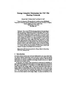
This model is based in Distributes Hash Tables (DHT), where the data is placed in numerous nodes. In order to publish a document, it is routed to the client whose ID is the most similar to the document’s ID. The process is repeated over and over until a close match is found. This model is used by Freenet, CAN, Chord, Pastry and Tapestry. The analyzed architectures and discovery and search algorithms organization can be seen in Figure 1.
Some modern P2P networks allow for resuming an interrupted download. Different download systems exist and they are covered below. 3.3.1
Single-source download
A file is downloaded from one or several sources, but not concurrently. This download type is used by Freenet, Soulseek, and MP2P. 3.3.2
Multi-source download
A file (or parts of it) is downloaded from multiple sources simultaneously. It is much faster. A “hash” is assigned to files, allowing the client application to verify a completed download. This type of downloading system is used by Gnutella, FastTrack and OpenNap. 3.3.3 Segmented multi-source download It is similar to the previous one, but it allows downloading parts of the file that are not sequential. In order to perform this type of downloading, the client application segments the file and builds associated metadata. EDonkey uses this type of download. 3.4 Advantages and disadvantages Above architectures have separate design goals for addressing different situations. (See summary in Table 1) .
Peer to Peer Filesharing Networks
Decentralized Type
FQM
DRM
Partially Decentralized Type
SQM
DIRM
Centralized Type
CIRM
Figure 1 Different Network Architecture
4
Decentralized P2P network Partially Centralized P2P network
Advantages No single point of failure Fast Searches
Centralized P2P Network
Fastest Searches
The centralized indices and repositories model
Short query time Simple
The distributed indexes and repositories model The flooded queries model The selective queries model
Tolerant to server failures.
The documents routing model
The system is scalable
Multi-source downloads
Fast download for big files
Efficient for small communities Larger bandwidth and scalability
Disadvantages Slow discovery. Several points of failure Wide geographical dispersion Single point of failure Single index repository Not scalable Server failure disables queries Large support needed at server Need to avoid obsolete updates between “brokers”. Limit request TTL (Time to Live). It can be exposed by an intermediate intrusion Any client in the network can change the results of the system Use segmented multi-source download for larger files
Table 1 Advantages and disadvantages of the analyzed item FG
Distribution Layer
FG FG AG AG AG
BFG
AG AG
AG
AG
BFG
AG AG
BFG
Access Layer CLI
CLI
CLI
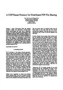
Figure 2 The access layer and the distribution layer with FG (Fixed Gateway) nodes, BFG.
4
Interconnection System Components
The interconnection system has two layers, the distribution layer and the access layer. Every P2P overlay network joined to this system has one fixed node and another backup fixed node belonging to the distribution layer (there could be more nodes called aggregated nodes). These types of nodes are called gateway nodes, so there are three types of gateway nodes, the fixed (FG), the backup fixed (BFG) and the
aggregated ones (AG). In other words, the distribution layer is composed by a FG node, a BFG node and several AG nodes that will interconnect every P2P network to the distribution layer. Some FGs are known; therefore a new FG node of a new network must be authenticated with one or several FG nodes of other networks. Every new AG node must be authenticated with the FG node of its own network. There must be authentication between gateways in order to know which one 5
is acting as a gateway. This authentication process creates two tables (distribution table and the access table) containing a list of gateway nodes. Initially, every gateway node must have the following information:
Its own IP address An identifier for its native P2P network Maximum number of supported connections from other gateways. Maximum load it can carry. What kind of files are in its network The maximum number of supported simultaneous connections from its own P2P network peers (used by AG nodes only). Metrics of other P2P networks (this metric is used by AG nodes and could be set manually or learned by other AG nodes) Kind of file downloading system (used by AG nodes only).
Every new gateway node, called AG node, will be in the distribution layer. The BFG node is an AG node, but it is the FG node’s designated successor; so it keeps its information as an AG and the same information of the FG node and acts as a backup. In case of a FG node failure, it becomes the FG node, and a new BFG node will be elected. The BFG node election is taken by the FG node as a function of available connections and the load the AG node can support. I will consider the BFG as an AG. FG nodes are used to maintain and manage the interconnection system. They help to establish adjacencies between AG nodes. AG nodes are used to forward data between P2P network peers. P2P network peers form the access layer. (See Figure 2). In order to create and maintain the distribution layer, there are two types of tables: the distribution table and the access table. Every gateway has those two tables. The access table is used by all gateways in the same P2P
network for communication. We can distinguish two types of distribution tables. The FG nodes’ distribution table is used to interconnect the FG nodes and interconnect AG nodes of different P2P networks. The AG nodes’ distribution table is used to forward the data from the peers of P2P networks to other AG nodes. 4.1 Access Table The FG node and all AG nodes in the same network form the access table. Each FG node maintains a unique access table. Additionally, the FG nodes and all AG nodes, in the same P2P network, have the same access table which is maintained by incremental updates. The access table has the following columns with registers: • •
• •
1st Column: N+1 registers with the IP of the FG node and the N AG nodes of its own network. 2nd Column: N registers with the maximum number of their allowed connections to other N AG nodes of other P2P network. 3rd Column: N registers with the load of the N AG nodes of its own network. 4th Column: N registers with the maximum number of their allowed simultaneous connections with its own P2P network peers.
My calculations of public domain P2P networks show in the worst case there are around 2000 AG nodes with around 2000 simultaneous connections each. That connection number holds for all peers of the network even with the most participants. (See my article [19]). When the system is searching for and downloading a file not in its own network, there are enough available connections. Therefore, 2000 AG nodes with around 2000 available connections should be set as a default value. But the parameter of simultaneous connections could be increased or
6
decreased manually or by the computer capacity.
• •
4.2 Distribution Table The FG nodes’ distribution table is formed by FG nodes of other networks. This information is obtained through other FG nodes. It is maintained by incremental updates. The “architecture design and management” section will discuss how to obtain that table. The distribution table has the following columns with registers: • • • • •
1st Column: N registers with the IP of the N FG nodes of the N other P2P networks. 2nd Column: N registers with the IP of the N BFG nodes of the N other P2P networks. 3rd Column: N registers with the network identifier of those FG nodes. 4th Column: N registers with the maximum number of allowed connections of those FG nodes. 5th Column: N registers with the maximum load that can carry out those FG nodes.
The AG nodes’ distribution table is formed by AG nodes of other networks. Every time an AG node forms its distribution table, it sends a query to the FG node in its network. The FG node forwards the query to all FG nodes in its distribution table. The FG nodes of all other networks will reply with the IP of the AG node in its network with most available number of connections. These entries will be added to the AG nodes distribution table. So, the AG node distribution table information is obtained through the FG nodes and is maintained by incremental updates. The distribution table has the following columns with registers: •
1st Column: N registers with the IP of the N AG nodes of the N other P2P networks.
• • •
2nd Column: N registers with the network identifier of those AG nodes. 3rd Column: N registers with the maximum number of allowed connections of those AG nodes. 4th Column: N registers with the maximum load that can carry out those AG nodes. 5th Column: N registers with the type of files it can be searched in their P2P networks. 6th Column: N registers with the metric associated to those N P2P networks. This metric is set manually in the local gateway, or learned by other gateways.
4.3 Metric The metric is used for downloading purposes only. It shows which one is the best network to download a file. It is used by the peers of every network to elect what is the best P2P network for downloading. The metric depends on the following parameters (all values between ]0, 1]): Number of Users (NU): This parameter is determined by the number of users who has the file requested. If a file is shared by more than 100 users, this parameter will be set to 1. Otherwise, it will be the number of user divided by 100. The gateways of a network will inform the number of users who share the file requested in order to calculate the NU. File Size (FS): It establishes a relationship between the size of the file and the download system used. It will create a table for each download system related with the size of the file. Therefore, a multi-source download system with a small file will have a value of 1. Also, a segmented multi-source download system with a big file will have a value of 1 too. Queue System (QS): When a download is done from another peer, there is a download queue system. Every queue system should have its network and performance analyzed. A network 7
with best queue performance will have a value of 1. Peers Bandwidth (PB): A peer with 10 Mbps or more available upload bandwidth will have a value of 1. Otherwise, its available bandwidth is divided by 10. The final metric of every interconnected network is: Metric = NU·FS·QS·PB
(1)
3. In the case of a centralized network, such as Soulseek network, new AG nodes have to be created in the network. A little bit of code in P2P clients have to be changed to use those new AG nodes in the network. The new code will send the search to the AG nodes in case of not finding any file in its own network. AG nodes can be static, learned by other peers, or learned by the servers or the super-peers of the network. It could be updated every time when a peer joins a network.
The desirable metric value is 1. All AG nodes in the same P2P network will have the same metric of other P2P networks. The metric value could be set manually for the local AG node, if it is for controlling the local weight of every partial metric or having the FG node to distribute it to AG nodes. 5
Architecture design and management
The distribution layer nodes can be normal nodes with an additional service which allow them to interconnect within the distribution layer network. These nodes must have great processing capacity and high bandwidth. Peers must release connections to AG nodes after finishing the search query. In order to implement an interconnection system, there could be three possibilities: 1. In the case of a partially centralized architecture with servers, such as eDonkey or OpenNap networks, the servers can be used as AG nodes. In this case, there will not be any change in the P2P clients’ code. 2. In the case of a partially centralized architecture with super-peers, such as Gnutella 2 or FastTrack networks, the super-peers can be used as AG nodes. Some P2P clients’ applications can be configured as super-peers and have additional code for joining the interconnection system.
As it has been aforementioned, several gateways of the same network can exist in the distribution layer (the FG node, the BGF node, and one or several AG nodes). The FG node must know the existence of all AG nodes in its P2P network by the access table. No more than one FG node and over 2000 AG nodes are needed in order to support all peers of a P2P network for searching and downloading from other P2P networks (every AG node will support up to 2000 peers connections). There could be AG nodes in the same P2P network that would have connections with the same AG node of the other network. Figure 3 shows the network design. As it can be seen, the FG nodes would have connections with other FG nodes of the other networks (lines formed by black points). The AG nodes would have connections with the FG of its own P2P network (lines formed by red points) and with the selected AG nodes of the other networks (solid black lines). In order to design a scalable and structured interconnection system for joining every new P2P network, it needs a routing algorithm between the FG nodes. The FG nodes identify and communicate with other FG nodes; a new FG node can establish the first connection with any FG node in this network randomly.
8
G1 AG
AG AG
FG
AG AG
FG
AG
G2
AG
AG
NetA
NetD
B
A AG
G3
AG
AG
FG
AG AG
FG
AG
NetC
AG
AG
NetB
G4
Figure 3 Four P2P networks interconnected by the interconnection system
A FG node will try to become adjacent to at least one other FG node previously known and become neighbors. The information gathered from adjacent FG nodes is not a complete FG nodes’ distribution table. Instead, FG nodes can tell each other of their changes in their distribution tables. In other words, new FG nodes advertise their information with other FG nodes; and, they reply with what is lacking in their distribution tables. This process allows FG nodes to share routing information with adjacent nodes and to build its distribution databases. Independently, each FG node then runs the Shortest Path First (SPF) algorithm [20] on the distribution database to determine the best routes to a destination. The SPF algorithm adds up the cost, which is a value based on the hops to the destination, the maximum number of simultaneous supported connections from other gateways, and the maximum load that it can carry out (the last two could be set manually) for each connection between the FG node and the destination. It also sends an identifier of its own P2P network and what kind of files that its P2P network has, without affecting on the cost value. The FG node then chooses the lowest cost path to add to
its distribution table. The lower value is better, e.g. if there are multiple paths to a destination, the lowest cost path is preferred. The traffic forwarded in FG nodes’ interconnection will be the FG nodes’ distribution table and tables with AG nodes of P2P networks with its number of available connections from other gateways and their available load. 6
Joining or leaving the system and node failures
When nodes fail or leave the interconnection system, the distribution database has to be updated. The system management is different according the type of gateway node (FG node, BFG node or AG node). When a FG node fails or leaves the network or a new FG joins the network, other FG nodes receiving those updates must rerun the SPF algorithm to recalculate routes. Prolonged entries, failures or leavings can severely affect performance. Also, the constant updates may prevent distribution databases from converging. 9
Because this system interconnect P2P filesharing networks, P2P clients leavings and new joining should be routine events, but FG nodes have to be quite stable. When a new node joins the distribution layer as a FG node of a new P2P network, it must authenticate with one or several other FG nodes of other P2P networks. The new FG node has to send its initial information to its adjacent FG nodes. With this information, its adjacent FG node will add a new entry to its distribution table and distribute the new entry over the FG nodes network. FG nodes are the stable gateway nodes of the interconnection system and important elements. To verify a FG node has not left or failed, the adjacent nodes will send every ten minutes a keep-alive message. If there is no response within 60 seconds, a failure or disconnection is verified. If there is a failure or disconnection, the SPF algorithm must run again. FG will be substituted by the BFG of its own P2P network and that change is distributed over the FG nodes network until the system has converged. When an old FG node returns to the system, it will become an AG node and will be elected a BFG due it supposed stability.
number of allowed connections. In this case, the connection establishment is sent to the successor gateway. Two tables have to be maintained for joining or leaving the interconnection system by the gateways. 6.1 FG nodes’ distribution table maintenance The distribution table of the FG nodes needs to be updated in order to have the optimum performance. The system proposed for maintaining the FG nodes’ distribution table, is as follows:
When a new node joins the distribution layer as an AG node, it sends a query to the FG node of its own P2P network. The FG node will request its own access table and distribution table. The access table will be saved. The distribution table will be used to send queries to other P2P network FG nodes in order to know to which other P2P network AG nodes could be connected. The other FG nodes will consult their own access table and they will set which will be the designated AG node and the feasible successors of their network for establishing the connection. This election will be as a function of available connections and the load of the gateways. As a function of the received data, the new gateway sends the connection establishment to the selected gateways. This connection will be refused by a remote gateway if this gateway has reached the maximum
Every time a FG node sends a query to other FG node and receives a reply, the counter for both gateways for this entry is reset to 0. Even if a change in the distribution database does not occur, routing information is periodically refreshed. If no query is sent to other FG node in its distribution table during ten minutes, it sends a keep-alive message to the adjacent FG nodes. This keep-alive message is used to verify that the adjacent FG nodes are still alive. If there is no reply in 60 seconds from the other FG nodes due to an exit or a failure, it will send a query to the BFG node of this network in order to have a substitute to the one that has failed. 6.2 AG nodes’ distribution table maintenance
The distribution table of the AG nodes needs to be updated in order to have the optimum performance for forwarding data between P2P network peers. The system proposed for maintaining the AG nodes’ distribution table, is as follows:
Every time a gateway sends a search query to another gateway and gets back a reply, the counter for both gateways for this entry is reset to 0. 10
Even there is no change in the distribution database, the routing information is periodically refreshed. If there has been no search query sent to a gateway in its distribution table for ten minutes, it will send a keep-alive message to the adjacent gateways. This keep-alive message is used to verify that the adjacent nodes are still alive. If there is no reply in 60 seconds from the other gateway, e.g. due to an exit or a failure, it will send a query to the fixed gateway of this network in order to have a substitute for the one that has failed. This decision is taken by the fixed gateway as a function of available connections and the load of the gateways.
The connection between the AG node and the peers in its network is occasional. That connection is only established if a search or a download is to be done. So, in case of an AG node failure, all peers using that failed AG node as the gateway will have a list of backup AG nodes. This list could be obtained by the AG node every time a peer is connected to an AG node or by other peers of its network. 6.3 Access table maintenance The FG node is the responsible to maintain the access table. Every new AG keep-alive message sent to the FG node will add an entry in the access table. All AG nodes will send keep-alive messages every ten minutes to the FG node in its own network to reset the counter of their entries to 0. Every time an AG node sends a query to a FG node to find an adjacent AG, the counter for this entry in the access table is reset to 0. Those entries with no keepalive messages in ten minutes will be deleted from FG node’s access table. New entries or deleted entries will be sent by the FG node as incremental updates to all AG nodes in its network. 6.4 Fault tolerant system management
The first time a P2P file sharing network joins the system, there should have at least one FG node and one AG node. It is preferable that those nodes have high Internet connection bandwidth and great processing capacity. In case there is only one AG node, the FG node will elect the AG node as a BFG node. In case there are more than one AG nodes, the BFG node election is taken by the FG node as a function of available connections and the load the AG node can support. When the BFG node fails, the FG node will elect a new one. Once the BFG node is elected, it will act as an AG node. And, it will receive additional information from the FG node in order to substitute when the FG failures. Because the access table is the same for all AG nodes and the FG node in the same P2P network, it will not need any information to be sent. Otherwise, the BFG node will need the FG nodes distribution table. So, every time the distribution table of the FG node is changed, the FG node will send this new information to the BFG node. BFG node will not send any information to other FG nodes; it will keep the information only, until it becomes a FG node. Using access table maintenance, BFG node knows if the FG node is alive. If BFG sees the FG node has failed, it will wait for a query from any AG node in its network or a query from a FG node of other network to become FG node. If this query is sent first, the BFG node will send immediately an AG keep-alive message in order to know the FG node failure. Once the BFG has become a FG node, it will elect a new BFG node as a function of available connections and the load the AG node can support. 7
Download System management
The greatest problem is to exchange data between peers of different networks. Given that communication through the distribution layer, the network gateways can be the responsible for transferring those data and make the translation between clients. This option will support low changes over the P2P networks and the actual clients; but it will support big load over the 11
distribution layer. In order to distribute the load, when a P2P client selects a file to download, it is established a relationship between some AG nodes by their distribution table. This relationship can be done by pairs of AG nodes of both P2P networks. The number of relationships can be determined as a function of the file size that is going to be downloaded. So the P2P client will download the file as it were located in the AG nodes. When a P2P client sends a query, it is initially sent to its own P2P network. If no result can be found, the search is sent to its network gateway (the AG node). The AG node looks up its distribution table and will be ordered to send the search to the other AG nodes in its distribution table. It also looks up the type of file that can be searched (some networks allow audio searches only). That will minimize the waste of resources and bandwidth. Every AG node, that receives that query, will send the search to its P2P network and will receive the results. These results will be sent to the source AG node with an identifier of its network. The identifier will be used to find the associated metric from the local AG node. Finally, the result of the query is sent to the peer that had requested it. This result will have the name or names of the found files, the network where it was found, and the associated metric. Table 2 shows the file download possibilities between P2P file sharing networks. As an example of the system operation, figure 3 is used. In this case there is only 2 gateways in order to do the download. Once the file to be downloaded is selected (placed in NetB, Computer B), the P2P client (Computer A, placed in NetA) sends the query to its gateway G1. G1 looks up its access table and sends a query to all AG nodes of its own P2P network in order to know which one is connected with an AG node of the P2P network NetB. The number of AG nodes that is needed will be as a function of the file size to be downloaded. The election of the AG nodes will be as a function From
To
of their load available and the available number of supported connections. In this case it only needs one AG node; and it will be the G2. G1 and G2 send the query to download to G3 and G4 respectively. G3 and G4 will establish a connection between them in order to not downloading the same pieces of the file elected and to use load balancing when it is being downloaded. Notice that both P2P have to support multi-source downloading or segmented multi-source downloading. For Computer B, it will be as if two peers were downloading the file in its own P2P network. G3 and G4 will transmit the data to G1 and G2 respectively. Finally G1 and G2 will transmit the data to Computer A. Notice that the file could be downloaded from one or various peers of the P2P source network. It could be controlled by G3 and G4. 8
Conclusions and future work
Several P2P file sharing networks have been analyzed based on their architecture, structure, searching algorithm and downloading system. All of these characteristics have their advantages and disadvantages and each of them performs better than the other ones according to the working environment or a desirable parameter. An interconnection system between all the analyzed networks has been proposed. It allows searching in every P2P network and downloading from every P2P network. The system mixes a centralized architecture (forwarding the access table) and a totally decentralized (forwarding the distribution table). The system is based on two types of tables. The first one, the distribution table, is used to know to which nodes the gateway has to forward the data. The second one, the access table, is used to know which nodes are in the same P2P network.
How 12
single-source system
multi-source system
multi-source system multi-source system segmented multi-source system segmented multi-source system
segmented multi-source system
single-source, multi-source or segmented multisource system single-source system
The transfer is only done by a pair of AG nodes because multi-source and segmented multi-source systems supports single-source downloading.
The transfer is only done by a pair of AG nodes. In this case the AG node of the multi-source system will transfer data from all peers and it will be sent to the AG node of the singlesource system. multi-source The transfer can be done by pairs of AG nodes. Load system balancing can be provided using packets between AG nodes segmented multi- The transfer can be done by pairs of AG nodes because source system segmented multi-source systems supports multi-source downloading. Load balancing can be provided. single-source The transfer is only done by a pair of AG nodes. In this case system the AG node of the multi-source system will transfer data from all peers and it will be sent to the AG node of the singlesource system. multi-source The transfer is done by pairs of AG nodes. In this case the system AG nodes of the segmented multi-source system will request data in order from all peers and it will be sent to the AG nodes of the multi-source system. This case needs packets between the AG nodes of the segmented multi-source system to request the data in order and load balancing. segmented multi- The transfer can be done by pairs of AG. Load balancing can source system be provided using packets between AG nodes. Table 2: File download possibilities between P2P file sharing networks.
At the FG nodes level, the system uses the Shortest Path First algorithm in order to determine the best routes to a destination. This path is used to forward the table with the best connections of a P2P network. Otherwise, at the AG level, it is a centralized model where the FG controls which AG nodes are in the P2P network and there is a BFG node in order to have fault-tolerance and which AG nodes can act as a support for the transmission of the files between P2P networks. The limitations of the gateway nodes (FG nodes and AG nodes) are constrained by the maximum number of simultaneous supportable connections from other gateways and the maximum load that they can carry out. If each P2P network attached to this interconnection system has potential of finding
a file, the proposed system will increase the probability of finding the desired file. The proposed method doesn’t depend on any specific network; it is open to existing network and new ones. The use of load balancing will permit to download larger files. As a future work, the author will try to obtain how many AG connections are needed to download the file as a function of the size of the file to download. On the other hand, experimental results are needed to adjust metric parameters, in order to select the best found file to download. The proposed system is now being developed for some existing public P2P file sharing networks.
13
Peer Services", IEEE INFOCOM 2003, April 2003.
Bibliography [1]
[2]
J. Lloret Mauri, G. Fuster, J. R. Diaz Santos, M. Esteve Domingo. Analysis and characterization of Peer-to-Peer Filesharing Networks. WSEAS TRANSACTIONS on SYSTEMS. Issue 7, Volume 3. Pages 2574-2579. September 2004
[11]
Eytan Adar and Bernardo Huberman. Free riding on gnutella. First Monday, 5(10), October 2000.
[12]
Nathaniel Leibowitz, Matei Ripeanu, and Adam Wierzbicki. Deconstructing the Kazaa Network, , 3rd IEEE Workshop on Internet Applications (WIAPP'03), June 2003, San Jose, CA
[13]
I. Clarke et al. Freenet: A distributed anonymous information storage and retrieval system, ICSI Workshop on Design Issues in Anonymity and Unobservability, Int'l Computer Science Inst., 2000.
CDI Working group, available at, http://www.ietf.org/html.charters/cdicharter.html
[3]
M. Day, B. Cain, G. Tomlinson, P. Rzewski. A Model for Content Internetworking (CDI). RFC 3466. February 2003. Available at http://rfc.net/rfc3466.txt
[4]
Shareaza, available at, http://www.shareaza.com/
[14]
OpenNap http://opennap.sourceforge.net/
[5]
MLDonkey, available at, http://mldonkey.berlios.de/
[15]
[6]
Morpheus, available at, http://www.morpheus.com
Oliver Heckmann and Axel Bock. The eDonkey 2000 Protocol. Technical Report KOM-TR-08-2002, Multim. Communications Lab, Darmstadt University of Technology, December 2002.
[7]
The giFT Project, available http://gift.sourceforge.net/
[16]
Soulseek http://www.slsk.org
[17]
MP2P http://www.blubster.com/protocol1.html
[18]
Wikipedia http://www.wikipedia.org/wiki/Peer-topeer
[19]
J. Lloret, B. Molina, C. Palau, M. Esteve. Public Peer-To-Peer Filesharing Networks Evaluation. The 2nd Iasted International Conference On Communication And Computer Networks (CCN 2004). MIT Cambridge, MA, USA. November 2004
[20]
Cormen, T. H.; Leiserson C. E.; & Rivest R. L. (1990) Introduction to
[8]
at,
Benno J. Overeinder, Etienne Posthumus, Frances M.T. Brazier. Integrating Peer-to-Peer Networking and Computing in the AgentScape Framework. Second International Conference on Peer-to-Peer Computing (P2P'02). September, 2002
[9]
cP2Pc: Integrating P2P networks. Ihor Kuz, Maarten van Steen, www.nlnet.nl/project/cp2pc/20030620cp2pc.pdf
[10]
Michel, B. Scott, Dharap, J., Xu, R., and Reiher, P. "General Purpose Infrastructure for Networked Peer-to-
14
Algorithms. MIT Press. ISBN 0-26203141-8 About the Author Jaime Lloret is graduated in Physics Science in 1997 and in Electronic Engineering in 2003 at University of Valencia (Spain). He is a Cisco Certified Network Professional Instructor and he is an Associated Professor at Polytechnic University of Valencia. He has been working as a network administrator in several companies. Actually, he is researching on P2P File-sharing Networks. He is author of several articles on P2P networks, some of them are referenced in this article. He can be reached at:
[email protected]
15