Apr 9, 1997 - Ann Arbor, MI 48108-3266 ... for the initiative is partially provided by the government and partially by the member companies. ... Project is just one of the contributions that Delphi Saginaw is making to the RRM effort. 2. Project ...
RRM Document 7-GD031.0
Interim Status Report
Submitted to Rapid Response Manufacturing (RRM) General Motors Key Project Contact: Biren Prasad: (810) 696-5487 (8-366-5487)
April 9, 1997
I. Report Number . EDSIRRMJACE!Shape.,opt,003
3. Report Covered 2. Report Date Eebruary 17,J 99.7 . . AugusLl993.c.. Septemberl99.6. ...
4. Titk and Subtitle: RRM Shape Optimization -- Stage I Interim Report 5a. GM Project Team Jeff Sutter Mitch Donnenwerth Gary Patelski Joe Streng Chris Cantu Steve Soicer 6. Performing Organization EDS/ACE Group 140 I Crooks Road Trov, Ml 48084, USA 9. Sponsoring Agency: RRM Delphi- Saginaw Division Samnaw, MI
Sb. EDS Project Team Biren Prasad Mohammad B. Shadmehr Mark Steinbach, Tom Goodman Nandu Kamat John LeToumeau 7. Types of Report Technical 8. Contract or Grant Number: RRM IO. Number of Pages 18 Pages II. Number of References: 7
12. Supplementary Notes: A Proiect Plan for Sta"e II submitted in 1997 as a follow uo to this document 13. Abstract: The shape optimization project, as it was originally defined, is discussed. Its history since its inception in 1993, what it hoped to accomplish then, and what has been actually accomplished so far are presented. We call the completion of this portion of the RRM Shape Optimization as Stage I. Stage II development ofRRM Shape Optimization Project started in November of 1996. Plans for this Stage II development (Stage II development is scheduled to be finished by Fall 1997) are also briefly discussed. The details about the RRM Stage II Plans can be found in Reference 5. 14. Subject Terms: RRM
Concurrent Engineering Shape Optimization Mechanica UG Bridee
15. Availability Statements: National Center for Manufacturing Sciences 3025 Boardwalk Ann Arbor, MI 48108-3266 (313) 995-0300
2 RRM Shape Optimization Stage I Report, Jan. 1997
Interim Status R~port RRM Shape Optimization Project -1 Summary
The shape optimization project, as it was originally defined, is discussed. Its history since its inception in 1993, what it hoped to accomplish then, and what has been actually accomplished so far are presented. We call the completion of this portion of the RRM Shape Optimization Project as Stage I. Stage II development of RRM Shape Optimization Project started in November of 1996. Plans for this Stage II development (Stage II development is scheduled to be finished by Fall 1997) are also briefly discussed. The detailed plans about the RRM Stage II Project can be found in Reference 5.
1.
Background
The Rapid Response Manufacturing Consortium (RRM) is a U.S. Government initiative aimed at developing and implementing world-class technical solutions to manufacturing problems. Member companies are urged to explore computer-based tools, either through development or purchase, in search of ways to make them respond more rapidly to market requirements. Funding for the initiative is partially provided by the government and partially by the member companies. Major companies participating in this initiative are: General Motors, Ford, United Technologies (Pratt & Whitney Division), and Texas Instruments. As a member of the Rapid Response Manufacturing Consortium, Delphi Saginaw has agreed to invest some of its resource in the areas of CAD/CAM/CAE for the purpose of exploring how these technologies can help to rapidly deploy new, innovative products. The Shape Optimization Project is just one of the contributions that Delphi Saginaw is making to the RRM effort.
2.
Project Participants
The project was originally a partnership between RRM members General Motors and Texas Instruments with EDS being involved through GM. The participants on the TI side were with the project till mid 1994.
Tl •
Ed Rehg, Peter Nies, and Lucian Brasier.
3 RRM Shape Optimization Stage I Report, Jan. I 997
GM ... ............ ..... • .. Jef!'Sutter.ofthe columns-groupwhoinitiated-theproject in 1993 ,· •
Mitch Donnenwerth of the columns group.
•
Gary Patelski and Joe Streng.
•
Chris Cantu and Steve Spicer of the Intermediate Shaft group.
•
Randy Herring, the FEA consultant to the columns and intermediate shaft groups.
EDS
3.
•
Mohammad B. Shadmehr, Mark Steinbach, and Tom Goodman, ACE Knowledge Engineers
•
Biren Prasad, ACE team consultant
•
Nandu Kamat, CAEfEngineering Analyst
•
Pat Race and John LeTourneau, ACE Team Leaders
Project Goals
The primary goal of the project was to come up with the techniques that would allow the optimization of the volume of a geometric part subject to geometric, engineering, and manufacturing constraints. The constraints were to be captured with a Knowledge-based Engineering package such as ICAD (1-5]. It was deemed necessary for the knowledge base to interface with an analysis package (such as FEA) as some of the constraints involved would be too complex to be analyzed without such a package [6-7]. It was also desired to make procedures as generic as possible so that one could switch parts or analysis packages without having to start from scratch [7]. As stated in the Phase zero document[4] submitted to RRM in late 1993, the development goal
was to: "Jointly collaborate on the design and validation of ICAD product models and software interface modules for the purpose of optimizing product geometry (minimizing mass/cost while ensuring functionality). The software system will modify part geometry in response to finite element and other analysis, and will ultimately reflect all constraints of the manufacturing process. The software system will be tested on a representative part by each participating company, and will interface with the specific analytical tools used by each member to simulate the forming or field use of their part."
3.1 Project Objectives The following were the project objectives: • Use ICAD software to capture the knowledge of the current and future design of parts for the generation of a new system prior to an initial built
4 RRM Shape Optimization Stage I Report,
Jan. 1997
•
Integrate a current DAS knowledge-base (current design and manufacturing parameters, engineering design and manufacturing criteria), and the various analysis models (e.g., ··· ........... MECHANICA)thatare·perforrnedintoanintegrateddesignoptirnizationsystem(DOS):·
4.
Stage I System Architecture
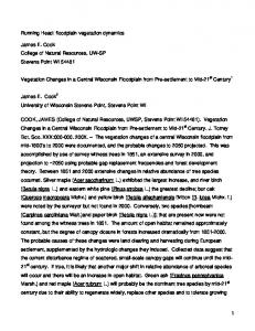
Figure I below (from the phase zero document [4]), shows the system architecture that was envisioned (now called Stage I development) for shape optimization project. According to this vision, shape optimization would be achieved via a feedback loop comprised of the knowledge base and the FEA analysis tool. The knowledge base attempts to reduce the volume or structural weight. At each step it checks to make sure no geometric, engineering, or manufacturing constraints are violated. Some of these engineering constraints are too complex to check with closed form equations. That is where the FEA analysis is used. A close examination of Figure I reveals that except for the box in the middle labeled "Engine to modify features based on analysis results" everything else is self explanatory for anyone familiar with FEA analysis and knowledge-based engineering. What goes in that box was going to be one of the challenges of this project. User Specific Analysis Tools
User Specific Knowledge Base
1--------------------------1 '0
'
... - -
I
II
Geometry
:
:
: I
:I FEA :I : Thermal : : Stress : Engine to 1---~·I I : Classical : modify I I I _____________ 1 I !.., features based on analysis results
~---~· I
Engineering : I
Constraints : ~--..-~·
!---1~
'' ' ''' '' '' ' '' '' ' ''
I
(existing)
I
I I I
Manufacturing Constraints
-- --- --- --- -.
(ICAD) featurized Model for the part
I
I I
Algorithm for modification of this featurized model
'' ' ---------------------------'
I
Stop
Figure I: System Overview 5 RRM Shape Optimization Stage I Report, Jan. 1997
5.
Stage I Development (9/1993- 9/1996):
In stage l of development, ( 1993-1996), we chose Mechanica Structure as an FEA program to do a linear static finite element analysis.
5.1 Project History Right from the beginning it was decided that the knowledge-based tool of choice would be ICAD and the FEA tool of choice for Delphi-Saginaw would be Mechanica. ICAD was chosen for its capabilities and its existing user base in Delphi-Saginaw. Mechanica was fairly new at the time with no user base in Delphi-Saginaw; it was chosen for two notable capabilities: automatic generation of a mesh, and the use of the p-method (as opposed to the conventional h-method) which allows the software to work towards convergence by increasing the order of the polynomials without having to resort to building a finer mesh (which is the case for the hmethod). The project began with an attempt to make a geometric model of the tilt housing, a steering column component. It was soon realized that a model of a generic tilt housing would be more appropriate because: •
The tilt housing geometry is extremely complex. This results in high development time as well as high computation time for the manipulation of the model.
•
There is no one tilt housing; rather there are multiple parts in production all of which share certain major features and differ in minor ones.
A geometric model of a generic tilt housing was built in ICAD as depicted in Figure 2. Next several interviews were held with Delphi Saginaw engineers and many of the engineering constraints on the tilt housing were documented and built into the ICAD model. The documentation of these interviews and the resulting engineering documents are appended to this report.
6 RRM Shape Optimization Stage I Report, Jan. 1997
0 Figure 2: a generic tilt housing The next step was to build an "ICAD-to-Mechanica" bridge. Since ICAD's parent company, Concentra, is an RRM member it was suggested that they build the bridge as part of their in kind contribution to RRM. Concentra agreed, but the RRM committee in charge did not approve of this project. Therefore, building the bridge became a deliverable of this project. 7
RRM Shape Optimization Stage I Report, Jan. 1997
It was decided to take advantage ofUnigraphics as an intermediary. UG already had links to both ICAD and Mechanica and could import/export geometry to them. This meant that we only needed to build part of the bridge from scratch: the part the engineering information is going to travel on. .. .... ... lCADiriOd\!Jes were Written for this purpose lliid the bridge was functfonal in 1995.
/ Figure 3: ICAD Mechanica bridge
5.2 ICAD Mechanica Bridge Figure 3 shows how the bridge works. ICAD passes geometry by Writing an ICAD binary file (*.ibf). UG user function ICADE! is then employed to produce a UG part file (*.prt) from the ICAD binary file. Next, UG is employed to read the geometry from the part file and produce a Mechanica Neutral File (*.mnf). The geometric part of the bridge is now completed. Next, ICAD modules written for this project edit the *.mnf file and attach the engineering information in appropriate locations. The neutral file is then fed to Mechanica which runs its analysis and produces a number of text files as output. Building the bridge enabled FEA analysis to proceed. Much time was spent on this and many issues considered. See the Discussion section for a thorough presentation. The development work on the Shape Optimization Project first focused on the heuristic approach. However, as previously mentioned, the rules governing this method are difficult to ascertain. The work that was done operated with a single rule: identify an unfilleted edge in high stress areas, add a fillet to it and try again. Even this simple rule met with some limited success. Late in 1995, with the heuristic approach not making any new headway and with a new faster version of Mechanica being on the verge of release, it was decided to give the parametric 8
RRM Shape Optimization Stage I Report, Jan. 1997
approach another chance. But fearing long processing times to still be a problem it was proposed that a portion of the tilt housing geometry be considered first [3]. This portion (a flange) was
· carefullychoserisodiafit wol.lid present ailoable yet nonfriVial probtem:. Soon after this proposal, the following took place:
(a) A technical roadblock was encountered involving a conflict between the capabilities of the chosen FEA software and the lab validation testing. This led to investigations of some alternative methods. (b) The principal knowledge engineer working on the project was transferred to another division within Delphi. (c) The Delphi-S project champion was transferred out of the chosen columns product group. Lack of cooperation from the columns group in assigning knowledgeable personnel to cooperate with the other knowledge engineers assigned to the project led to the decision to consider switching to another group. Three criteria were proposed for the new group to be considered. One, that the part that is to be modeled be simple enough so that we do not experience the problems we were experiencing before due to extreme geometric complexity. Two, that the engineering tests on the part all be linear (since Mechanica can only handle linear cases). Three, that the group be willing and able to provide experts who can cooperate with the knowledge engineers on the project. The Intermediate shaft group and one of their yokes was chosen. A geometric model of the yoke was built in ICAD as depicted in Figure 4. This model was finished in Summer 1996. The engineering information on the yoke has not yet been captured.
9 RRM Shape Optimization Stage I Report, Jan. 1997
Figure 4: A yoke Test part In August 1996, it was discovered that the new releases of the three software packages involved (ICAD, UG, Mechanica) had some incompatibilities. They broke the functional part of the ICAD Mechanica bridge through which the engineering information was required to travel. When EDS knowledge engineer look at the problem, they identified the nature of the problem. It required more time to make this bridge functional. Unfortunately, the problem was discovered shortly before the KE was leaving the company. He did not had a chance to fix the problem. New plans of actions are being put in to continue work on this Stage II project. Stage I of the project was concluded towards the end of September 1996. In the following, we describe what has been accomplished in Stage I of this project. They are described through flow details 1 through 8 in the following and in Figure 3. Process Flow Detail #1: This consists of two major steps. First to pass the geometry and second to utilize !CAD functions. • Pass geometl)· from !CAD in the form of an !CAD Bina!)' File (*.IBF) • Utilizing !CAD function (with-writer (unigraphics . .. )) Process Flow Detail #2 This step is used to convert the binary file into an UG part file. IO
RRM Shape Optimization Stage I Report, Jan. 1997
• •
Convert !CAD Binary File (*.!BF) into UGII Part File (*.PRT). Utilizing Unix script ibj2prt to call Unigraphics User FWlction ICADE!.
Process Flow Detail #3: The nexi step is to import a part file into the Unigraphics .. • Import Part File (*.PRT) into Unigraphics. • Utilizing UGII command line interface. Process Flow Detail #4 • Export Unigraphics geometry from Part File (*.PRT) to Mechanica Neutral File (*.MNF). • Utilizing Unix script prt2mnfto execute UGil!Mechanica User FWlction. Process Flow Detail #5 • Modify Mcchanica Neutral File (* .MNF) to include loads and boWldary conditions, material properties, and analysis definition. Process Flow Detail #6 • Import Mechanica Neutral File (* .MNF) into Mechanica, AutoMesh, and execute analysis. • Utilizing Mechanica Script Language. Process Flow Detail #7 • Mechanica outputs numerous results files containing finite element data. Process Flow Detail #8 • Results information is post-processed in !CAD.
The figure 3 graphically depicts the 8 process flow details discussed earlier.
II
RRM Shape Optimization Stage I Report, Jan. 1997
6.
Other Deliverables
The Shape Optimization project gave rise to two off shoots during the three years it has been in existence. These offshoots were both full projects in their own right and were done to completion. While very useful, these projects were only marginally related to Shape Optimization.
6.1
The ACE Toolkit
The idea for the ACE Toolkit[2] grew out of the joint GM TI effort to develop standards that would simplify code sharing. It was hoped that this would encourage close cooperation of the two companies on the Shape Optimization project. More specifically, it was decided to develop standards for internal documentation of ICAD modules. The lead author looked into this issue in late Winter 1994. It was found that a previous attempt, internal to ACE at Delphi Saginaw, was made on this subject in 1992. The idea grew from developing standards for internal documentation to developing standards and guidelines for the entire knowledge engineering process based on Expert System Life Cycle. EDS KEs picked up the old material, updated and revised it thoroughly, and added some new material. Fellow ACE knowledge engineer -- one of the co-authors of the original version -reviewed and edited the entire work. RRM coworkers at TI encouraged the effort all along. The Toolkit was released to RRM in June 1994. A presentation to an RRM wide audience was made later in July 1994.
6.2 FEA analysis of the T-piece The T-piece as depicted in Figure 5 below is one of the parts made by Delphi Saginaw Steering Systems. While learning how to use Mechanica effectively, EDS/KE offered to do analysis and optimization on the part for Delphi-Saginaw engineers Tony Dodak and Brian McNally. They were enthusiastic about this project and provided EDS with the information it needed. EDS built a parametric model and ran several analyses. EDS/KE did some sensitivity and optimization studies as well. However, EDS/KE had a tough time correlating Mechanica's answers with what contractors running Nastran were providing. The participants on all sides lost some interest at this point and the project slowly died down.
12 RRM Shape Optimization Stage I Report, Jan. 1997
Figure 5: a T-piece
7.
Stage II Plan of Development
The following issues were investigated prior to starting the Stage-II of Shape Optimization development. •
Whether or not the ICAD-to-Mechanica bridge constructed by EDS/KE in 1994-95 needs to be upgraded to work with the newest versions ofMechanica (which is in version 16.00). Mechanicajumped the version number to match that of Pro-Engineer. This led to 8 version numbers higher than the one (Mechanica version 8) the bridge was built for. And on the ICAD side two version numbers higher than the one (ICAD version 4) the bridge was built for.
•
Whether or not the current ICAD-Mechanica bridge can readily handle passing of parameters as well as geometry.
•
Identify the cost and time required in upgrading the ICAD-Mechanica bridge code (FEA Interface) that currently exist.
•
Determine if the original programming resource is available to get this enhancement done. If not what would take for an alternate resource to complete the work. 13 RRM Shape Optimization Stage I Report, Jan. 1997
• ·• •
Investigate the cost and time required to build a new bridge using Nastran. Determine if it is cost effective for another KE to build a new bridge in Nastran or upgrade the old Interface. Determine the level of human resources required in completing the assignments in each case.
It was important that we chose an approach that took least amount oftime in each case. Also choose an analysis system that the
•
•
User is most comfortable with
•
Had prior experience
•
Willing to use in the future, and
•
The customer knowledge exists within an organization.
Investigate the shortcomings of optimization in FEA (Mechanica, Abacus or Nastran) with an eye toward how ICAD and AI techniques may be employed to compensate for them. One such shortcoming is that Mechanica cannot represent nonlinear parameter relationships in sensitivity analysis and optimization. RRM customers request that Mechanica be only considered a fall back system for the purpose_of developing Stage II.
Based on the investigations the following configurations were chosen for Stage II. • • •
!CAD - total product model, pre- and post-processing UGII -- geometric gateway to Nastran Stage II Development. -- In stage II ofthis Shape Optimization Project (Sept. 1996Sept. 1997), GM/EDS chose a new architecture, so that we can plug in any DAS model into a Design Optimization System (DOS). Nastran was the program of choice for FEA. NASTRAN or ABACUS are widely used programs by GM both at Delphi-S and Delphi-I divisions.
The objective of this RRM/Stage II project is to develop a Design Optimization infrastructure for linking the analysis with a DAS model, pipe-lining the design variables and constraints to the optimizer of the Nastran program. The linkage will enable any part -- for which a DAS model exits -- to be easily optimized.
8.
Choice of A System Architecture - Discussion
There are several schools of thought regarding shape modification, among them: the finite element approach, the rules of thumb approach, the parametric approach, and hybrid approaches. I. The Finite Element Approach relies heavily on the manual application of a finite element mesh during the discretization of the model; a process which can require up to a week of an engineer's time. After reviewing stress results, the engineer manipulates the elements' nodal 14 RRM Shape Optimization Stage I Report, Jan. 1997
points to counteract high stress regions. Often this technique is employed in the creation of basis vectors to categorize the appearance of the shape change[ I]. We have elected not to ..... coiisiaeftliisapproachfoshapemodificatioriiiitliis projecf diie fo··frs.reliance on sl.lch manual. interaction within a finite element modeling software. We do not assume our end users to be finite element specialists, capable of carrying out such detailed tasks. We will instead rely on the technological advantages of the industry's off-the-self mesh generators. 2. The Rules of Thumb (or heuristic) Approach relies on identifying appropriate rules which a finite element analyst might follow in executing a shape modification; whether they are a result of cognitive thought or simple intuition [7]. Often these rules are developed by individual analysts after years of experience of designing a particular product. An example of this might be a rule for how large of a fillet radius is needed between two perpendicular surfaces in order to reduce stress in the area. The advantage to building a knowledge base of these rules is that they might be applicable to a multitude of design problems, regardless of the product's geometry. The disadvantage to such an approach is that the knowledge is difficult to capture. Rules probably don't exist for every type of design consideration that is possible. Even so, finding an expert who possesses that knowledge is not always possible. 3. The Parametric Approach relies on the identification of the critical dimensions of the geometry being studied, and the evaluation of the results as the dimensions are modified. An advantage derived from such an approach is that an answer to the problem can always be found. A disadvantage to such a technique is that in order for it to be a robust system, all major possibilities for shape change requires to be thought of ahead of time [7]. 4. The hybrid approaches combine some of the aforementioned ones [7]. For example, one could use a heuristic to choose one feature over another and then use parametric optimization to optimize the chosen feature. From the techniques mentioned above, the development work on the Shape Optimization Project first focused on the heuristic approach. It was deemed most valuable because of its advantages in reusability for generic product geometry; it could have been built as a stand-alone ICAD module that could be reused by many business teams within Delphi Saginaw. However, as previously mentioned, the rules governing this method are difficult to ascertain. More in-depth knowledge about this process of shape optimization needed to be gathered before such a modification engine could be built. Experts could not be identified from whom to gather such knowledge, leaving an insurmountable knowledge gap. The work that was done operated with a single rule: identify an unfilleted edge in high stress areas, add a fillet to it and try again. Even this simple rule met with some success. Part of the problem all along was the speed of the whole process, which is why the rules of thumb approach was the first one tried. Parametric optimization of a geometry as complex as the one initially used for this project takes too long to be of any value. However, the rules of thumb approach did not make enough progress so it was decided to give the parametric approach a try. When the system architecture depicted in Figure I was envisioned back in 1993, FEA software packages did just analysis; now many of them come equipped with their own optimization engine. These can typically optimize a number of specified parameters over a specified range. Obviously, with this capability one can do shape optimization entirely within the FEA package. Does that mean that the architecture depicted in Figure I is now obsolete? Not necessarily. 15
RRM Shape Optimization Stage I Report, Jan. 1997
·· -
The optimization that takes place in most FEA softwares is purely parametric [7]. This means that the architecture depicted in Figure 1 could only be value-added if it is capable of at least one of - · ····· the following• 1. modifying the geometry in a non-parametric fashion in response to analysis results 2. representing complex parameter relationships the FEA package is incapable of representing. For example, some packages (such as Mechanica) can only represent linear relationships among the parameters involved. 3. guiding the search of the parameter space much more efficiently than a general purpose (gradient based) optimizer does. For example, it might be possible to prune significant chunks of the space through algorithms based on the product knowledge base. 4. handling manufacturing constraints that can not be represented by an algebraic formula. (The constraints that can be represented algebraically could be added to the constraint set of the parametric optimizer.) Needless to say, the architecture depicted in Figure 1 is much more costly to build and to run than it is to do purely parametric optimization within the confines of an FEA software package. Thus, there are two choices for the system architecture: The first choice allows only geometric optimization. A parametric geometric model is built either directly in the FEA software package or in a CAD package and then imported. Geometric, engineering, and (algebraic) manufacturing constraints are specified. FEA and optimization are both performed within the FEA software package [7]. The other choice goes beyond geometric optimization. The non-geometric model is built in a knowledge-based tool such as ICAD. The geometric, engineering, and manufacturing constraints are also built into the ICAD model. The FEA software is employed to perform FEA analysis and parametric optimization. The results of this optimization are fed back to the knowledge base, evaluated, and used to change the geometry non-parametrically or adjust the parameter space to accommodate other constraints [7]. The advantages of the geometric approach over the other approach are: being well understood, having a high chance of success, easier to build, less costly to run, available in the short term. The advantages of the knowledge-based approach over the parametric one are: being more general, being more capable of coming up with not-anticipated optimizations, being more powerful than the parametric approach, and that it may be necessary for some parts due to complex manufacturing constraints. There are non-technical issues to consider when choosing the system architecture as well. The parametric approach provides short-term sure-fire success. The knowledge-based approach, however, is more long-term and may not produce much success since it is not fully understood how to do some of the things enumerated above. Even if it does produce success it may be the 20-80 scenario. That is, the parametric approach may produce 80% of the benefits for 20"/o of the effort. The parametric approach is about using generative technology well. The knowledge-based approach is about building a knowledge-based interface to optimizer. It is riskier (you may not succeed) but (if you do) the rewards are higher. This is exactly the kind of idea that is at the heart 16
RRM Shape Optimization Stage I Report, Jan. 1997
of the RRM consortium. The government is partially subsidizing this effort because it is supposed to be new, innovative, research oriented, and risky. -~-
In fact, the best scenario is to pursue both in parallel and see how much (if any) more gain there is by going beyond parametric optimization. During Stage II of RRM Shape Optimization development, we plan to investigate both these options. The RRM consortium is due to end in Fall 1997 and the current source of funding for this project will end with that.
9. RRM Shape Optimization Project Benefits DELPHI expects that RRM/Shape Optimization project will •
Support GM/RRM Virtual Prototyping Product/Manufacturing Design Strategy
•
Reduce Developmental time of Part advanced concepts
•
Facilitate design standardization by providing a consistent design methodology
•
Greater Implementation of Manufacturabilities in steering system design
•
Facilitate "what if" concept by considering alternatives early in the design
•
Allow engineer to re-evaluate design as a result of changing customer requirements
•
Increase our understanding of Part/packaging parameters effect the drivers reaction to the Part
•
Support the Component Set Strategy by utilizing carry-over parts when applicable
•
Assist in material reduction for new parts
•
Establish relationship between Part packaging parameters
•
Generate the design parameters for the Part, before the Part is built
•
Aid in preservation of design expertise
•
Other Business Opportunities •
Cost savings from minimum material usage.
•
Wider range of materials and processes.
•
Reduced Prototyping.
•
Faster-to-Market designs.
•
Better engineered parts.
17 RRM Shape Optimization Stage I Report, Jan. 1997
10. Concluding Remarks An exercise of integrating analysis and optimization codes with a knowledge-based system (ICAD) - as explained by Stage I of Shape Optimization project -- was an important step for RRM. It gave GM/EDS an understanding of the strengths and limitations of the chosen codes and the chosen architecture for building an initial shape optimization capability. Stage I development was carried out with Mechanica since at that time Mechanica was a product newly introduced. It had some new features such as automatic mesh generator and p-elements, which seemed attractive. Mechanica, however, had a limited user base at Delphi-Saginaw. GM/EDS is taking this learning experience (from Stage I) and now is applying it to Nastran, which has a wider user base across Delphi. The next development -- "Stage II of shape Optimization project" -- is devoted towards building both a parametric-based and a knowledge-based optimization capability using Nastran FEA program. Yoke will be used as a test case for verifying the proposed procedures.
11. References [!] J. Fukushima, Y. Kobayashi, M. Nakamura, Y. Otsuba, K. Kurumatani, "Development of Shape Optimization Technique Based on The Basis Vector Method", SAE Document 950575, Toyota Motor Corp.
[2] M.B. Shadmehr, T.D. Goodman, "ACE Toolkit, Volume I", published through Rapid Response Manufacturing Consortium, June 1994 [3] M.A. Steinbach, M.B. Shadmehr, "A progress report and proposal for the RRM Shape Optimization project", internal report, November 1995 [4) J. Sutter, "Shape Optimization Project, Phase zero document", November 1993 [5] B. Prasad, et. al., "RRM Shape Optimization -- Stage II Project Plan", November 1996. [6] Prasad, B., 1996, "Concurrent Engineering Fundamentals, Volume I: Integrated Product and Process Organization", New Jersey: Prentice Hall PTR. [7) Prasad, B., 1997, "Concurrent Engineering Fundamentals, Volume II: Integrated Product Development'', New Jersey: Prentice Hall PTR.
18 RRM Shape Optimization Stage I Report, Jan. 1997