Proceedings, XVII IMEKO World Congress, June 22 – 27, 2003, Dubrovnik, Croatia
TC1
Proceedings, XVII IMEKO World Congress, June 22 – 27, 2003, Dubrovnik, Croatia
TC4
XVII IMEKO World Congress Metrology in the 3rd Millennium June 22−27, 2003, Dubrovnik, Croatia
INTERNAL TRIGGER ERRORS IN MICROCONTROLLER-BASED MEASUREMENTS Ferran Reverter, Josep Jordana, Ramon Pallàs-Areny Technical Univ. of Catalonia, Electronic Eng. Dept, Technical School of Castelldefels Avda. del Canal Olímpic s/n, 08860 Castelldefels, Spain,
[email protected]. Abstract − Measurements based on triggering a time counter display trigger uncertainty, which depends on input signal noise and slew rate, and on input channel noise. This last is specified for bench-top instruments but not for microcontrollers with embedded time counters, which are very attractive to implement period-to-code converters intended for sensor interfaces. Because power-supply rails in digital systems are very noisy, we have analysed the effect of Gaussian white noise and sine wave interference added to the PIC16F873 power supply pin. For a triangular input signal, the standard deviation of 1000 period readings increases with the amplitude of the added noise, as expected, and it is always larger when the period is determined from the rising edge of the timed signal rather than from its falling edge. Keywords: Period microcontroller.
measurement,
trigger
uT ( rms ) =
1.4 Eni2 + Ens2 ∆V ∆ t
(1)
where Eni2 is the specified noise variance at the instrument input channel, Ens2 is the variance of the noise superimposed on the measured signal, and ∆V/∆t is the signal slew rate at trigger point. Both noise sources Eni2 and Ens2 are normally assumed to be Gaussian. The 1.4 factor (= √2) results from considering that random noise equally affects each trigger point involved in a period measurement. From (1), a fast slew rate minimizes uT, but the capacitor-charging involved in some sensor interfaces have a slow slew rate [2] [3]. Microcontrollers with embedded counters measure the period of an input signal by calculating the elapsed time between two signal edges through the subtraction of their respective times of occurrence, as determined by crossing the trigger threshold of an input port [5]. The time unit is the machine cycle, that equals the number of internal clock periods needed to execute a single instruction. Equation (1) still applies but the internal trigger noise Eni2 is not specified. This internal noise arises from at least three different sources: (a) Inherent (thermal) noise; (b) Power supply rails noise; and (c) Program-dependent noise. It has been previously shown [6] that when power-supply rails noise increases, Eni2 increases too, which results in an increased time uncertainty. Program commands also affect Eni2, which results in quantized results when the measured signal has slow slew rate [7]. The behaviour of microcontroller’s input pins that are Schmitt trigger buffers, is determined by an upper voltage threshold VTH and a lower voltage threshold VTL. Rising signal edges are detected when they exceed VTH, and falling edges are detected when they decrease below VTL. Furthermore, current microcontrollers use to include several input pins which are sensitive to external events, and can thus interrupt the main program. There is often an external interrupt pin and/or a capture mode pin. This paper analyses the effects of power supply noise on VTH and VTL, and the resulting uncertainty when timing signals whose slew rate is slow enough to obtain a significant uT in (1). This uncertainty is compared to that resulting from noise directly added to the input signal.
noise,
1. INTRODUCTION The measurement of quasi-digital quantities such as frequency, period, time interval, pulse width, and phase, often relies on measuring the elapsed time between two successive crossings of a voltage threshold: the first threshold crossing triggers a time counter and the second threshold crossing stops it. Alternatively, the first threshold crossing starts the counter, which is stopped after a selected numbers of additional threshold crossings have happened. This technique offers a convenient method to obtain a digital code from different measurands by placing a suitable modulating sensor in a variable oscillator whose output frequency or period is measured by a microcontroller with an embedded counter. At low frequencies and for a given resolution, period measurements are preferred because they are faster than frequency measurements [1]. Some circuits intended for resistive sensors measure instead the charging [2] or discharging [3] time of a fixed capacitor. Whatever the measured quantity is, the uncertainty in the triggering point results in different readings for the same input signal, thus limiting the resolution. Bench-top instruments set in period mode suffer from the same problem, and their uncertainty is [4]
655
Proceedings, XVII IMEKO World Congress, June 22 – 27, 2003, Dubrovnik, Croatia
TC1
Proceedings, XVII IMEKO World Congress, June 22 – 27, 2003, Dubrovnik, Croatia
2. MATERIALS AND METHOD
laboratory dc power supply (Promax, FAC-662B). An Agilent 33120A function generator provides amplitudecontrollable Gaussian noise with 10 MHz bandwidth. In order to not significantly reduce noise bandwidth, the adder attenuator is based on a broad bandwidth op amp (AD844). The actual noise voltage in the power supply rail is monitored by a digital oscilloscope (Tektronix TDS5054). To compare the effect of power supply rail noise and input signal noise, we have successively added a 125 Hz sine wave interference to either the power supply voltage (Fig. 1) or the input signal (Fig. 2). Because of the different input characteristics of the power supply and trigger inputs, it is quite difficult to add white noise to them and ensure that the effective noise amplitude is the same in both inputs. Adding a sine wave interference allows us to ensure that the amplitude is the same and therefore the results (standard deviation of the period readings) can be directly compared. We have selected a 125 Hz interference because interference whose frequency is close to that of the input signal (here 100 Hz), results in an increased standard deviation, as compared to frequencies much higher or lower [6]. The rms amplitude of the added 125 Hz interference has been 25, 50, 75, and 100 mV. In Fig. 2, care has been taken to guarantee that the power supply voltage was reasonably free from external interference, so that the sine wave interference added to input signal could predominate over the internal trigger noise.
Figures 1 and 2 show the experimental set up to analyse the effect of noise added to, respectively, the power supply pin and the input signal. In both cases, the PIC16F873 microcontroller works at a clock frequency of 4 MHz. The function generator (Promax GFD-917) provides the signal to be measured (1 V/ms, 100 Hz triangular wave, i.e. 10 ms period). This signal is connected to (a) the external interrupt pin RB0/INT, and (b) the Capture1 input CCP1. Both pins include a Schmitt trigger buffer, and they can be programmed to yield an interrupt command when detecting either a rising edge or a falling edge. Measuring the period of the input signal using each mode yields information about the noise level associated to VTH and VTL. The 1 V/ms slew rate is slow enough for trigger errors to be clearly perceptible in the count number. Timer1 (16 bits) counts the time between two consecutive rising or falling edges by incrementing its output each microsecond. The time count of the microcontroller is sent to a PC via a serial link (EIA-232) implemented with a MAX233 supplied from a separate power supply. Using separated power supplies for the microcontroller and the serial interface chip prevents transients (about 173 kHz) in power supply lines resulting from the operation of the MAX233 from interfering with the power supply rails of the microcontroller. A decoupling capacitor (C1 = 100 nF) is connected between the microcontroller power supply pins, as recommended by the manufacturer, in order to reduce conducted interference in normal operating condition. The loop that waits for the interruption signal indicating that the input voltage has reached the trigger level, and starts or stops the timer, has been written in assembler language. That program sequence establishes an uncertainty (quantization) of ±3 when counting input signals having slow slew rate [7]. The remaining of the control program has been written in C programming language. Power supply Promax FAC-662B
0V
AD844
Function Generator Agilent 33120A Gaussian white noise or sine wave interference
5 V + noise
R2
R3
TL071
10 ms
R2
R3
VDD RB0/INT or Signal+ RC2/CCP1 noise
PIC 16F873
RS-232
Period measurements have been taken every 0.5 s until totalling 1000 measurements. The microcontroller did not perform any other task while counting. The user interface has been implemented by LabVIEWTM. Trigger uncertainty has been evaluated by the standard deviation and histogram of the measured time periods.
Oscilloscope Tektronix TDS5054 C1
0V
R1
+
AD844
VDD
+ -
C1
10 ms Function Generator Promax GFD-917
Gaussian white noise or sine wave interference
5V
5V
Fig. 2. Experimental set up to analyse the effect of input signal noise on the trigger noise. (R1 = R2 = R3 = 1 kΩ, C1 = 100 nF.)
+
Function Generator Promax GFD-917
Voltage Regulator (LM7805)
Power supply Promax FAC-662B
10 V
R1
10 V
Function Generator Agilent 33120A
TC4
R4
Input Signal
RB0/INT or RC2/CCP1
PIC 16F873
3. EXPERIMENTAL RESULTS AND DISCUSSION For the amplitude values of the Gaussian, white noise added to the power supply rails, the histogram of the 1000 periods counted was roughly Gaussian. Fig. 3 shows the standard deviation of each set of 1000 period measurements for different noise amplitudes and depending on whether triggering by rising or falling signal edges. In the absence of added noise, the standard deviation is larger than that attributable to the ±1 counting uncertainty, which shows that there is internal noise at the Schmitt trigger input. Also, the standard deviation is very close for
RS-232
Fig. 1. Experimental set up to analyse the effect of power supply noise on the internal trigger noise. (R1 = 1 kΩ + 47 Ω, R2 = R3 = R4 = 1 kΩ, C1 = 100 nF.)
In Fig. 1, the effect of power supply noise on the trigger thresholds VTH and VTL has been analysed by adding different amounts of Gaussian, white noise: 0, 25, 50, 75, and 100 mV (rms) to the 5 V supply voltage provided by a 656
Proceedings, XVII IMEKO World Congress, June 22 – 27, 2003, Dubrovnik, Croatia
TC1
Proceedings, XVII IMEKO World Congress, June 22 – 27, 2003, Dubrovnik, Croatia
both signal edges (about 3 µs), and limits the resolution to less than 12 bit for a 10 ms period.
shape of the histograms of 1000 period measurements are analogous to the probability distribution function (PDF) of a sine wave plus random noise. Fig. 4 shows the standard deviation of each set of 1000 measurements for the four cases considered and different interference amplitudes. The standard deviation of the 1000 periods when the interference is added to the power supply pin is larger when measuring between the rising edges than when measuring between the falling edges of the triangular input signal. This result entirely agrees with those in Fig. 3. When the interference is directly added to the input signal, the standard deviation also increases with the amplitude of the interference, it is larger than when adding the interference to the power supply voltage, and it is similar for both input signal edges. Therefore, an interfering voltage in the power supply yields an attenuated voltage at the trigger threshold, and that attenuation is larger in VTL than in VTH. This different dependence may result from the internal circuits that determine the trigger thresholds [8]. Therefore, eqn. (1) should be modified to include the dependence of Eni2 on the selected voltage threshold of the input Schmitt trigger. Histograms corresponding to the experiments in Fig. 4 show a ±3 count quantization when using the VTH threshold, which can be explained from the analysis of the waiting loop performed by the microcontroller [7]. If the VTL threshold is used instead, the histograms are not so clearly affected by that ±3 count quantization. This results shows that the program-induced noise in VTL is smaller than that induced in VTH.
50 Time between rising edges Time between falling edges
Standard deviation (us)
40
30
20
10
0 0
25
50
75
TC4
100
Noise amplitude (mVrms)
Fig. 3. Effect of Gaussian white noise added to the power supply on the standard deviation of the period of a 100 Hz triangular signal measured between rising or falling edges.
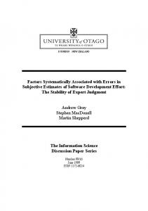
When adding noise to the power supply voltage, the standard deviation increases with the noise amplitude, as expected from (1), but in addition it has larger amplitude and rate of increase when the period is determined from the rising edge rather than from the falling edge. When adding a 125 Hz sine wave interference either to the power supply pin or to the triangular input signal, the 150
Interference added to the power supply, falling edges Interference added to the power supply, rising edges Interference added to the input signal, falling edges Interference added to the input signal, rising edges
Standard deviation (us)
100
50
0
0
10
20
30
40 50 60 Noise amplitude (mV RMS)
70
80
90
100
Fig. 4. Effect of a 125 Hz sine wave interference added to the power supply or to the input signal, on the standard deviation of 1000 periods of a 100 Hz triangular signal measured between rising or falling edges.
657
Proceedings, XVII IMEKO World Congress, June 22 – 27, 2003, Dubrovnik, Croatia
TC1
Proceedings, XVII IMEKO World Congress, June 22 – 27, 2003, Dubrovnik, Croatia
Repeating the same experiments in Figs. 3 and 4 but using the CCP1 input instead of the external interrupt pin RB0/INT, does not reveal any significant difference. Therefore, the input noise associated to the VTL and VTH trigger levels for those two different Schmitt trigger inputs can be considered to be the same.
TC4
ACKNOWLEDGMENTS This project has been funded by the Spanish CICYT, projects TAP99-0742 and DPI2002-00707. The authors also appreciate the technical support of Francis López. REFERENCES
4. CONCLUSIONS
[1] N.V. Kirianaki, S.Y. Yurish, N.O. Shpak, V.P. Deynega, "Data Acquisition and Signal Processing for Smart Sensors", John Wiley & Sons, Chichester (U.K.), 2002. [2] D. Cox, "Implementing an Ohmmeter/temperature Sensor". AN512. Chandler (AZ). Microchip Technology, 1997. [3] L. Bierl, "Precise measurements with the MSP430". Report Texas Instruments, 1996. [4] A. J. Bouwens, "Digital Instrumentation", McGraw-Hill, New York, 1984. [5] J. B. Peatman, "Designing with PIC Microcontrollers", Prentice-Hall, Upper Saddle River (NJ, USA), 1997. [6] F. Reverter, O. Casas, J. Jordana, J.M. Torrents, R. PallàsAreny, "Uncertainty in Period Measurements Using Embedded Counters", Proceedings Eurosensors XVI, Prague, 15–18 September 2002, 328–331, ISBN: 80-01-02576-4. [7] F. Reverter, J. Jordana, R. Pallàs-Areny, "Program-Dependent Uncertainty in Period-to-Code Converters Based on Counters Embedded in Microcontrollers", IEEE-IMTC 2003, Vail, Colorado (USA), May 20–22, 2003. (accepted). [8] I. M. Filanovsky, H. Baltes, "CMOS Schmitt Trigger Design", IEEE Trans. Circuits and Systems, vol. 41, no. 1, pp. 46-49, January 1994.
The uncertainty in trigger-based measurements depends on internal trigger noise, which is not specified in microcontrollers’ data sheets. For the PIC16F873, that internal trigger noise increases with power supply noise and it is smaller for measurements triggered by the falling edge of the input signal rather than by their rising edge. The effect of noise or interference added to the input signal is larger than that of noise or interference added to the power supply pin. If the noise added to the input signal predominates over the internal trigger noise (Ens2 >> Eni2), the standard deviation is the same regardless of whether the time period is measured between the rising edges or the falling edges of that input signal. If, on the contrary, the power supply noise predominates, the trigger uncertainty depends on the internal trigger noise (Eni2), and this one depends on the voltage threshold used (VTL o VTH). Therefore, when considering trigger noise uncertainty it is convenient to distinguish two different internal trigger noise variances: EniL2, associated to VTL, and EniH2, associated to VTH.
Authors: Ferran Reverter, Josep Jordana, Ramon Pallàs-Areny. Technical Univ. of Catalonia, Electronic Eng. Dept, Technical School of Castelldefels. Avda. del Canal Olímpic s/n, 08860 Castelldefels, Spain, +34-93-4137096, fax +34-93-4137007,
[email protected]
658