ACC99-IEEE0280
INTERNET-BASED CLIENT/SERVER VIRTUAL INSTRUMENT DESIGNS FOR REAL-TIME REMOTE-ACCESS CONTROL ENGINEERING LABORATORY Jamahl Overstreet, and Anthony Tzes1 Polytechnic University Six Metrotech Center Brooklyn, NY 11201 Abstract This article describes the design of a generic virtual instrument used for real-time experimentation purposes at Polytechnic University’s control engineering laboratory in a remote-access environment. These instruments can be freely downloaded and the remote user can access the laboratory facilities from anywhere and anytime. The philosophy behind our Internet-accessed remote laboratory is based on a client/server computer configuration. The server, situated near the experiment, transfers to it the received command signals transmitted by the client. The client locally computes the command signal based on the reference waveform and the transmitted system response. The remote user can select the transmission protocol, switch between asynchronous and synchronous sampling, use either a batch or a recursive data transfer mode, and view the experimental testbed. Our approach is distinct from others since it can offer more flexibility and responsibility to the client-side, since the remote user compiles, and executes locally the controller. Issues concerned with network’s reliability, dynamic delay factor caused by the Internet’s traffic, concurrent user-access, and limited computing power have been addressed. The designed set of experiments is the first step towards our remote control laboratory. Introduction The virtual laboratory (VL) concept [1-4] allows students to continuously access their hypothetical experimental setups, and is rapidly becoming feasible due to the progress in Internetbased networking technology. In a typical VL-educational paradigm [5-8], the experiments are emulated via a fast processor and the students retrieve the experimental data over a computer network. In this paradigm, since the students need not to be exposed to the actual experimental setups, the virtual laboratories can remain continuously accessible. The advantages of the VLparadigm rely on the minimal cost to set up such a laboratory, since it only requires a robust communications network. There is no need for purchasing instruments, typically used in the actual setups, and the maintenance cost is negligible (occasional system-reboots).
1
Corresponding author: A. Tzes is with Polytechnic University, Mechatronics Laboratory, Six Metrotech Center, Brooklyn, NY 11201, E-mail:
[email protected], Phone: (718) 260-3722, FAX: (718) 260-3532.
Page 1 out of 25
September 15, 1998
ACC99-IEEE0280
The main concern in the VL-paradigm is the lack of students’ real-time interaction with the experiment; for this reason hybrid solutions, involving actual setups and remote-access techniques, have recently been investigated. In these cases the actual experimental setup is observed with a video-camera; live video (at a typical rate of 0.2 frames/sec) is sent to a Webpage, and the students’ remote computers receive the digitized compressed video feed. Although this approach offers some kind of real interaction, the use of World Wide Web for transmitting the experimental data (including video) introduces considerable delays. To further alleviate the random delays caused by the traffic on the Internet and their effects on the data acquisition process, some universities [9-14] use dedicated fast communication links and proprietary software designs for real-time remote experimentation. Other reported approaches rely on ‘batch processing’ [15,16] with/without ‘remote control-design downloading’ [17-19]. For the batch-mode processing/experimentation, shown in Figure 1, the remote user downloads the set of historical reference inputs to the server which operates the experiment. The server either has a set of predetermined controller-structures (with variable parameters) or can accept along with the reference signals the code that implements the controller strategy. After the code’s compilation and linking on the server-site, the server performs the experiment. The experiment runs for a preset finite amount of time while the system’s response is stored at the server. After the experiment is completed, the server transmits the historical response datafile in a batch mode to the client (remote user). The user observes the response, fine-tunes the controller structure and parameters in an off-line manner, and repeats the previous procedure until a satisfactory response is obtained. This scheme is not susceptible to any delays introduced by the Internet-traffic, since the controller is implemented locally and does not require any interaction with the user. Hybrid solutions have been offered, primarily in the telerobotics area [9,17], where the reference input is transmitted in almost real-time from the client to the server; the server acquires the reference signal, and in a similar manner executes the control strategy. The emphasis in most (if not all) current approaches for remote-experimentation relies on the principle that the server is responsible for the execution of the controller portion. More recently, hybrid schemes [20] where the controller parameters are tuned on-line at the client side while the server transmits the system’s response have been reported.
Page 2 out of 25
September 15, 1998
ACC99-IEEE0280
Figure 1: Current Remote-Access Experimentation Practice Scheme
Client Enhanced Internet-based Remote Laboratory Our approach, labeled I-abc (from the initials Internet-access-based control) shown in Figure 2, can provide the same features as the current practices used in other remote laboratories, yet it provides the user with additional options by granting more responsibility and authority (if needed) on the client side.
Figure 2: Client Enhanced Remote-Access Experimentation Practice Scheme The user can elect whether the client, or the server, side will implement and execute the controller. The advantages of performing remotely the computations for the controller implementation include among others: • Ability to utilize computationally powerful clients for implementation of complex control laws. This is the philosophy used in centralized process control, where a centralized computer
Page 3 out of 25
September 15, 1998
ACC99-IEEE0280
•
• •
•
(client) monitors a cluster of smart sensors/actuators and feeds to them the command signals. The calculation of these commands requires significant computational resources typically performed at the client-site. At the same time, this allows the use of less powerful and inexpensive server-computers, since their main load (only) consists of: a) the forwarding of the transmitted command signals to the actuators, b) the sampling of the system’s sensors, and c) the communication process back to the client of these sampled values. Although, this issue may not of direct concern towards the development of remote undergraduate experiments, it is essential in the implementation of graduate-level experiments. In these experiments, under development at Polytechnic University, dedicated microcontrollers [21,22] act as nodes to server-devices. For the client-side, fast DSP boards in a parallel computer architecture [23] are utilized to calculate in real-time sophisticated controllers (i.e., H ∞ , generalized predictive control, etc.). This cost for operation and implementation of our graduate control laboratory that exploits this powerful-client/microcontroller-server philosophy is considerably less compared to the traditional philosophy relying on standalone computers dedicated to each experiment. Ability to implement advanced control laws despite significant limitations on the server-side. This can be considered as a supplement to the previous noted item, with the cited difference that the user has no option of selecting the server’s computational power. This is typically encountered in several applications (i.e., autonomous vehicles, remote robotics), where the server-devices face several size and power consumption limitations. In these cases, servers with low power consumption requirements are used with the adverse effect of using reduced computational capability on the server-side. This obstacle can be bypassed by using the server as a plain communication-node and implementing the controllers on a remote client. Permission to maintain privacy of the implemented controller-code, since the controller is implemented and executed remotely. This issue might be of concern to students/researchers asked to download their code for compilation at the local site [19]. Additional flexibility in the controller design process, since the user is free to implement any type of controller at the client-side. Compared to the other cases, where a prefixed set of controllers is available at the server-site, this option is by far more versatile. Furthermore, it allows non-conventional computing environments (i.e., distributed computing, array processing) to be used for the controller implementation. Enhanced safety against downloaded viruses or ill-functioning programs, since the server does not compile or link any program locally. This is an issue of concern highlighted in Figure 1, where certain individuals can transmit programs for compilation at the server side which may be contaminated by software viruses. Even worse, other persons can download programs that violate the server’s file system safety (i.e., perform a disk format). The server’s functions in our ‘I-abc’ environment can be restricted against file transfers and compilations which can potentially hamper its integrity.
Overall, the I-abc philosophy assigns more authority and responsibility on the client side to implement and execute the controller. In the employed design, the client: a) receives in real-time, over the Internet-link the system’s response, b) computes the command signal, and c) transmits it to the experimental apparatus. This approach can potentially suffer from the delay caused by the traffic on the communication links and the possibility of data-packet losses. In addition, the
Page 4 out of 25
September 15, 1998
ACC99-IEEE0280
variety of computer resources that the user population operates (i.e., slow processors and storage devices), necessitates the development of a flexible and modular software code. For these purposes, we provide the user with a variety of options (e.g., synchronous, message verification schemes, 16-bit and 32-bit code versions, etc.) that can assist in circumventing some of these issues. I-abc Communication Protocol Attributes The five-layered UDP/IP or TCP/IP model [24], shown in Figure 3, was deployed for the communication part between the client and the server, where ‘Internet Protocol’ (IP)-datagrams are exchanged between the sending and receiving hosts through the network layer.
Figure 3: I-abc UDP/IP and/or TCP/IP-based Protocol Model The user can select either the User Datagram Protocol (UDP) or the Transmission Control Protocol (TCP) for the transport layer. TCP is a connection-oriented, full duplex service, and guarantees a reliable bi-directional stream of data. For the case of lost data, TCP requests retransmission, while it can discard duplicate data and reorder out of sequence data packets. UDP has reduced overhead and offers time service which can synchronize the client’s clock with the server’s clock on a network. However, unlike the reliable TCP network protocol, UDP provides a connectionless service in which data can be lost, duplicated, or arrive out of sequence. In the TCP protocol the client needs to specify its IP-address and port number; several clients with the same IP-address but different ports can be concurrently connected to the same port of the server. The UDP protocol does not require the fixing of the client’s port and a certain client switches randomly its ports during the exchange of messages. For both protocols, several users with different IPaddresses can concurrently access the same port of the server’s IP-address, as shown in Figure 4 which highlights the possible TCP/IP and UDP/IP client/server connection schemes. Through socket programming at the server’s transport level, we restrict the access to the server to only one user at any time.
Page 5 out of 25
September 15, 1998
ACC99-IEEE0280
Figure 4: Client/Server TCP and UDP Network Connection Schemes The typical datagrams transmitted between the client and server appear in Figure 5, where the client transmits data streams of 6 × 64 bits length comprised of the command signal u( k ) , confirmation token, priority code, video transmission request, size of temporary buffer, and size of captured frame. The necessity of these fields in the datagram exchanges between the client and server will become apparent from the established communication protocol. In order to enhance our security and block certain IP-addresses from accessing the server, we are using a firewall-option programmed at the server’s application layer; the same firewall disconnects someone after some time of controlling the experiment. The application layer protocol at the client verifies that the server has received the proper command signals (segments) with the correct sequence by bouncing between the client and the server a set of time-varying tokens created by a random number generator. Although this option is not needed for the TCP-based transmission (since clients and server automatically acknowledge the receipt of segments), it is useful for the UDP-based transmission to account against any lost messages, in which case the client retransmits these messages. Moreover, this token is used to validate the identity of the client, since the server expects a specific sequence of tokens to arrive at its port. This feature is useful for discarding
Page 6 out of 25
September 15, 1998
ACC99-IEEE0280
Figure 5: Client/Server Exchanged Datagrams unauthorized users who managed to broadcast into the server’s dedicated port during an already established client/server connection (despite the single user attribute forced by socket programming); these users will not be able to transmit the right (predetermined) token-sequence and the server will nullify the connection. Furthermore, the application layer saves in a datafile at the server-end: a) the IP-addresses of the clients which accessed the experiment, and b) the time that each connection was established. A password (priority code, 8 bytes) feature has been included to allocate priorities and privileges to various group of users (i.e., Polytechnic’s students have primary access rights compared to other Internet-users). For the case of transmitted video during the experiment, the client notifies the server to provide live video feed by turning on the ‘video transmission request’ flag. At the same time, the client requests the video frames to be captured at a given resolution (i.e., 640 × 480 pixels) and specifies its temporary video buffer size (TVBS-bytes). In this case, the server: a) transmits fast the system’s response y ( k ) , b) captures a video frame at the requested resolution and color depth, c) compresses the frame data (JPEG-format), d) splits the frame data into subframes of TVBS bytes, and e) transmits sequentially these subframes along with a header specifying the subframe number and the overall number of used subframes. The client is then responsible for (i) reordering, (ii) assemblying these subframes, and (iii) displaying the compressed frame while at the same time transmitting the control signals to the server. Overall, large video frame resolutions and video buffer size degrade the controller’s performance since the communication channel is loaded primarily with transmitting massive streams of video-data rather than handshaking the control command and the system response.
Page 7 out of 25
September 15, 1998
ACC99-IEEE0280
I-abc Virtual Instrument Design The adopted approach for the implementation of the communication protocol and controller does not require any software package on the client-side. For the case, where a user wants to supply his/her own controller-code, an optional generic C-compiler is needed to generate a Dynamic Link Library (DLL). This DLL is called by the software simulating the ‘Virtual Instrument’ (VI), which can be downloaded from the Web-page of the control laboratory at ‘http://mechanical.poly.edu’. The downloaded executable-VIs can run in a variety of MS-Windows platforms (i.e., Win 3.1, Windows ’95, and Windows-NT) while the minimal (recommended) client-computer configuration is a 486DX-66 (Pentium-75) MHz computer with 8MB (16MB, or more) of RAM, VGA (SVGA, or better) capable card with 512KB (1MB+), and 10 (20+) MB of free hard disk space. Compared to other similar approaches for remote-access laboratories, the attributes of our approach are: a) the VIs operate on commercially popular operating systems (Windows-based platforms) which can be found in the majority of computers used by students, b) the distributed programs are freeware resulting in a low implementation cost, and c) a modular and expandable architecture has been adopted for the software components, thus giving the users the option to extent the VI’s capabilities. The front end of the distributed VI appears in Figure 6, where a set of options are accessible to the user. These options are categorized into the following five groups according to their functionality. 1. The first group is related to the definition of the reference input. The user can elect to provide the discrete time reference values, r(k),k=1,.., by using one of the following methods. 1.A) These values are provided by sampling a supplied signal through an analog-todigital converter. Software drivers have been written for several data acquisition boards and the user is asked to use one of these boards for this purpose. The current list of ‘certified and tested’ boards is expanding with its most recent update found in the laboratory’s Web-page. The user is asked to provide the sampling period and observe several rules for the board’s configuration. The disadvantage of this option refers to the need of the user to be equipped with a data acquisition board and is considered to be the least pliable for the remote-access lab-concept. 1.B) The signal values are downloaded from a datafile, which is prewritten by the user. This is the most flexible data-entering method since the system can be excited with ‘irregular’ (aperiodic) signals. The format of the saved data stream is t , r (t ) . The drawback of this option is that the size of this file can be large for long experimentation intervals. Furthermore, due to the random delays caused in the Internet there is no promise that the stored values will be accessed and downloaded to the server over at their desired time intervals.
Page 8 out of 25
September 15, 1998
ACC99-IEEE0280
Figure 6: Virtual Instrument Front End
Page 9 out of 25
September 15, 1998
ACC99-IEEE0280
1.C) The user can synthesize in software periodic waveforms (square, ramp, and sinusoidal). The user has control over the amplitude, duty cycle, dc-offset, and period of the waveform through a set of slider bars. The position of these bars correspond to the values of the previous parameters and these values can be altered on-line. This is the most desirable option, since the transmitted values are computed based on the client’s current reference time. 2. The second group selects the open or closed loop architecture. 2.A) Since the reference signal is defined at the user side, for the open loop configuration, the client simply transmits over the network the set of these reference r ( k ) values. 2.B) The controller needed for the closed loop mode can be implemented either locally (at the server) or remotely (at the client). For the local configuration, the user transmits the compiled controller-DLL at the server, where it is linked, and executed. The user still transmits in the closed loop locally-implemented configuration the reference values r(k), k=1,... over the network. For the remote implementation, the system’s response sampled values y(k) are transmitted back to the client, where the user supplies a C-code that computes the command signal u(k)=f(u(k-j),r(k-j),y(k-j), j=1,..,N) based on the delayed command, reference, and system response samples. This portable C-code is compiled by the user as a Dynamic Link Library (DLL) according to a pre-specified template. The ‘mangled-name’ of the controller-DLL, along with the executable filename are then linked to the VI. For ease of experimentation, we have included several icon-driven controller-prototypes (i.e., on/off, proportional, and PID control), as well as 3N-slider bars that the user can use for real-time adjustment of the controller parameters. Furthermore, we have posted on the Web a database of pre-developed control laws (in PDF format) to assist system engineers in developing and testing additional control laws. 3. The third option is related to several issues adopted in the application layer’s ‘Application Programming Interface’ (API). These issues include software options that verify the data transmission’s integrity, the synchronized transmission option, the batch processing of data, and the source of controller execution. 3.A) The transmission verification scheme is an API-mechanism that ensures that the server has received the transmitted command values in the proper order. Since TCP/IP can only reorder the packets comprising a segment, this API forces the client to receive confirmation that the previous segment was received prior to any future transmissions. This option can be disabled by the user, who can elect whether the client should wait prior to transmitting the next command value u(k), until the server has confirmed that it received the previous command input u(k-1). The confirmation is accomplished by bouncing between the client-server a set of tokens. The client generates, via a random generator, tokens, which are being forwarded to the server. The server returns these tokens along with the system response back to the client, which is in a pause-state awaiting for the tokens’ arrival. Upon the token’s arrival and its value confirmation, the client resumes the controller’s computations. 3.B) The synchronous transmission option relates to an API-software that synchronizes the client with a periodic sampling signal. If this option is not selected, the client will send the next command signal as soon as it completes the computations. This results in an asynchronous transmission of the command values with a time-varying sampling time dictated
Page 10 out of 25
September 15, 1998
ACC99-IEEE0280
by the computational power of the client’s computer and the transmission delay (client-serverclient) of the Internet. If the TCP-protocol is selected, even in the synchronized case, the server transmits back to the client the system’s response at inner-sample instants; this primarily serves for recording purposes at the client-side of the system’s response. The aforementioned (3.A and 3.B) issues are highlighted in Figure 7 for the case of a utilized UDP-protocol, which displays all possible cases in a typical communication exchange between server and client. The even cases correspond to the instances where the verification option is enabled since the client (top portion at each subplot) waits for the bouncing of the transmitted token prior to its next transmission. The synchronized cases correspond to the 3rd, 4th, 7th, and 8th instances since the client transmits the command inputs at multiples of the sampling period Ts . Cases 1 through 4 are related to the open-loop configuration since the client transmits the reference input r ( t ) , while in the remaining cases (5 through 8) the command signal u( t ) is transmitted.
Figure 7: UDP/IP-based Client/Server Data Exchange Timing Flowchart If the user has enabled the `verification' option and has set the synchronization period Ts on a small value, there is a possibility that the `packet-receipt; token may arrive after the sampling period. In this case the client continues to wait until the token is returned, and keeps sending the previous value until the token's arrival. Once the token arrives, the client is synchronized with the clock and transmits the new value.
Page 11 out of 25
September 15, 1998
ACC99-IEEE0280
3.C) Another API controls the batch vs. real-time data transmission mode. In the batch mode, the user downloads at once to the server all reference values r(k), k=1,..,N. Subsequently, the server executes the experiment (open, or closed loop configuration), samples the system’s response and transmits back to the client all collected system response values y(k),k=1,..,N. In this mode, the problems caused by the Internet’s transmission delay do not exist, since the server executes the experiment (locally) based on the locally accessible r(k), y(k)-data. In the real-time mode, the client transmits in a sequential manner the command signals to the server, which executes the experiment; this process is repeated until the termination of the experiment. Although, this mode is susceptible to the transmission delay factor, it allows for real-time adjustment and fine-tuning of the controller’s parameters. 3.D) The local(server)-based or remote(client)-based nature of the computations is controlled by a distinct API. In the former case, the user downloads to the server the DLL that implements the controller. The server, then links this DLL to its VI. In the latter case (remote) the client links the controller’s DLL to the supplied executable file and starts the communication process. 4. The fourth group is related to the data presentation and storage alternatives. 4.A) The user can plot the experiment’s relevant data comprised of the reference r ( k ) , system response y( k ) , and commanded control u( k ) values on a color chart to allow for relative visual comparisons. 4.B) To account for the delays caused by Internet’s traffic and the processing at the server computer, we post on a horizontal-fill slide the transmission delay defined as the I s time (in msec) between the time instant where the client sends its datagram to the server, until the time that the client decodes the datagram bounced back by the server, as shown in Figure 8. Within this ‘transmission’ delay, we include the S s -time needed by the server to: a) decode the received datagram, b) send the command signal to the digital-to-analog converter, c) sample the system’s output, d) perform any optional video-related grabbing requests, e) assemble its datagram, and f) forward the assembled datagram to the IP-gateway. We should note that the S s -time can be comparable to the delay attributed to the Internet traffic ( S s ≅ Ti ) . The computational power of the client computer can be indirectly inferred by the amount of time that needs to compute the command signal. This Ds -time is also observed by a horizontal slide pointer indicating the execution time of the provided DLL. In a similar manner, the overall delay Ts (sampling period) between successive datagrams sent by the client is recorded (Ts ( k ) > I s ( k ) + Ds ( k )) . The factors that increase mostly Ts are the plot and data recording options; for the former option, the client needs considerable time to refresh its video memory while for the latter case the client needs to access the hard drive controller to record data in the hard disk. 4.C) These data items can be saved in a remote file specified by its path, and filename; the user can arbitrarily select the start and stop time (via a button-pointer) for saving the data in a datafile. To recover from typical file-storage errors (i.e., disk full, out of zone, file permission error), the user is provided with a set of informative features pointing to the error source.
Page 12 out of 25
September 15, 1998
ACC99-IEEE0280
Figure 8: Client-Responsible Datagram Exchange and Data Acquisition Timing Diagram 5. The fifth group pertains to the two parameters related to the video transmission option. 5.A) The captured frame size parameter has three settings associated with the frame’s resolution M × N in pixels ( M × N = 640 × 480, 320 × 240, and 160 × 120 ). To reduce the size of the captured frames, these are captured using a monochrome grabber board (256 gray levels, or 8 bits/pixel gray color depth). The uncompressed size of the frame is M × N × 8 bits and a typical JPEG compression results in a tenfold reduction of its size. 5.B) The client’s temporary video buffer size expressed in TVBS-bytes dictates the speed of reconstruction and update of a transmitted frame at the client end. The server splits the compressed image at portions of TVBS-bytes; a typical frame is divided into F = ( M × N × 8 ) (10 × 8 × TVBS) subframes. Under the assumption of a synchronous transmission where TVBS-bytes can be transmitted over a sampling period, the client will be able to reconstruct and display the entire frame after F periods. However, although the reconstruction rate of a frame can be expedited faster by increasing the buffer’s size, the communication channel’s bandwidth and the sampling period dictates this size; this is due to the need to transmit TVBS-bytes over a Ts time interval. Several precautions are embedded in the current implementation to account for possible extensions of the sampling period due to the transmitted video data stream. In all cases, the highest priority in the client’s operation is given to the computation and transmission of the command signal to the server. I-abc Mechatronics Laboratory Setup and Configuration The Internet-based remote-access laboratory paradigm was initiated at Polytechnic University in 1996 on an experimental basis. The students experimented with our planetary vehicle and designed simple on/off controllers. During this past academic year (97-98), several of our control and instrumentation experiments within the Mechatronics laboratory [25,26] have migrated and are currently running under this concept; in these experiments proportional and PID controllers are programmed and tested on a simple 3rd order system. The effects of the sampling time, actuator saturation, Internet traffic on the system’s performance have been addressed. During this
Page 13 out of 25
September 15, 1998
ACC99-IEEE0280
academic year (Fall 98) the first experiment will be offered in a university-wide basis in our ‘freshman engineering’ class. The typical network topology and configuration of an experimental setup appears in Figure 9. Each experimental station is equipped with a computer (Pentium-II 200MHz w./ 64Mb of RAM, running Windows NT ver. 4.0) which relies on National Instrument’s LabView graphical programming environment as its front end for data acquisition (NI-Lab-PC+ data acquisition card w./ 12-bit ADC and DAC). Power amplifiers are connected to Labview’s interface card and are subsequently interfaced to the experimental setups. A color camera (VHS-C w./ 525 × 400 pixels, 1 lux @F1:1.6) is attached to each ‘remote-access enabled’ experiment; the video frames are captured by a National Instruments image acquisition board (NI-1408) at a rate of 30 frames/second.
Figure 9: I-abc Network Topology/Experiment’s Configuration The typical maximum sampling rate used in these experiments is 100 Hz, and the maximum burst raw-data transfer between the computer and the setup is 20,000 bytes/sec. All computers in the lab are currently in a 10-Mbit subnet with typical inter-network communication rates up to 900Kbytes/sec; the subnet is linked to the school’s router with a 100Mbit link and a T-3 line (45Mbit/sec) is then used for connection to Internet. The students can dial-in to the University using analog modems (56Kbit/sec - max) or directly to the Mechatronics lab [25] using either analog phone or ISDN (128Kbit/sec) lines. Access rights have been provided to client-computers within Polytechnic University’s domain or to dial-in requests (PPP-enabled).
I-abc Mechatronics Laboratory Experiment Page 14 out of 25
September 15, 1998
ACC99-IEEE0280
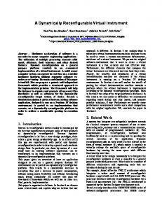
A typical experiment is concerned with the design of simple controllers (i.e., PID) for a given experimental setup. The students design the continuous controller using MATLAB’s Simulink. The controller is then discretized for a given sampling rate and the anticipated results using this discrete controller on the analog plant are provided. Subsequently, the students need to program this controller in C, create the DLL, embed it to the client and execute the integrated code. The integrated code consists of the compiled DLL and the core-executable code downloaded from the lab’s web-site (http://mechanical.poly.edu). Results using in-school as well as out-of-school connections are expected and the students are asked to comment on these. The deterioration on the system’s performance caused by the video-feed is examined and results with and without this feed are anticipated. To illustrate some of the aforementioned concepts, consider the control of a system with transfer 0.5 , shown in Figure 10. Based on the Ziegler-Nichols method a continuous PID function ( s + 1)3 1102 . controller is designed with transfer function 3.2 + + 0.384s (a low pass filter with high cutoff s is used to roll-off the high frequency spectrum). The discrete equivalent of this PID controller for 1102 . Ts 1 + z −1 0.384 a Ts -sampling period has a transfer function 32 . + + (1 − z −1 ) . The presented −1 2 1− z Ts remote controllers were designed based on a synchronous transmission with a desired Ts sampling period, implemented within the university’s network (client and server computers are in the same subnet).
Figure 10: Continuous, Discrete, and Remote PID Control Concepts The system response with the continuous, discrete, and remote controllers are shown in Figures 11 through 13 for the case where Ts = 55, 500, and 2000 msec respectively. We should note that the first case ( Ts = 55msec) corresponds to the asynchronous transmission, since the client transmits to the server the datagram as soon as it computes the control signal ( t I − t H = 0 at Figure 8). The reference signal is a periodic square waveform with amplitude 0.1 and 40 seconds period; for this Page 15 out of 25
September 15, 1998
ACC99-IEEE0280
input the control signal barely saturates when the sampling period exceeds 1000 msec. The succeeded actual sampling times Tsactual are displayed in Figure 14, where the maximum error Tsactual − Ts ≤ 50 msec; this error is attributed primarily to the time needed to encode/decode the datagrams and service system requests (i.e., refresh hard disk buffer) at the client and server ends. Occasional large spikes for the asynchronous mode ( Tsactual ≅ 55 msec) are due to the instantaneous traffic increase in the communication channel, or due to the need to retransmit the packet (IPrelated problem). Overall, the system’s response with the remote controller is similar to that of the discrete controlled one and the analysis with a fixed sampling rate can be considered valid (addressed for undergraduate students).
0.2
0.15
0.1
0.05
0
−0.05
−0.1 Reference Signal Analog Controller
−0.15
Discrete Controller Remote Controller
−0.2 0
10
20
30 seconds
40
50
60
Figure 11: System Response with Continuous, Discrete, and Remote ( Ts = 55 msec) Control
Page 16 out of 25
September 15, 1998
ACC99-IEEE0280
0.2
0.15
0.1
0.05
0
−0.05
−0.1 Reference Signal Analog Controller
−0.15
Discrete Controller Remote Controller
−0.2 0
10
20
30 seconds
40
50
60
Figure 12: System Response with Continuous, Discrete, and Remote ( Ts = 500 msec) Control
0.2
0.15
0.1
0.05
0
−0.05
−0.1 Reference Signal Analog Controller
−0.15
Discrete Controller Remote Controller
−0.2 0
10
20
30 seconds
40
50
60
Figure 13: System Response with Continuous, Discrete, and Remote ( Ts = 2000 msec) Control
Page 17 out of 25
September 15, 1998
ACC99-IEEE0280
2000 1800
Tactual (Sampling Period) in msec s
1600 1400 1200 1000 800 600 400 200 0
0
10
20
30 seconds
40
50
60
Figure 14: Actual Attained Sampling Periods Tsactual The system’s response with the video-transmission option enabled appears in Figure 15 for three video-frame resolutions and a temporary video buffer size of 200 bytes (TVBS=200 bytes). The added minimum time-overhead for the sole transmission of these 1600 bits over a 10Mbit/sec (56Kbit/sec) link is 0.16msec (28.5msec); the typical overhead to: a) compile the packet out of the video subframe data (shown in Figure 5), and b) transmit it to the client is 110msec (260msec). The responses shown in Figure 15 indicate a similar system response deterioration for all resolutions of the video frame; this is anticipated since the communication link is overloaded in all cases with the same traffic (200 bytes per transmission) irrespectively of the video-resolution. The only component affected by the different resolution is the server, which for higher resolutions needs to: a) capture a frame at a finer fidelity at a lower rate (since it takes longer to transmit one image), and b) compress and save this larger amount of video data to its hard drive. Figure 16 indicates the actual sampling times Tsactual for the three resolutions. The finer resolution, as expected from the previous observation, results in less often but larger sampling period variations (spikes) shown in Figure 16. Typical time periods (in seconds) to update one frame over a 10Mbit/sec high ( ≅ 20Kbit/sec low) bandwidth communication link are: TVBS-bytes 20 200 2,000
Page 18 out of 25
640 × 480 180.24(403.74) 23.44 (45.62) 1.62 (9.55)
320 × 240 48.67(140.96) 4.23 (13.33) 0.62 (2.98)
160 × 120 20.73(51.17) 1.82 (3.5) 0.13 (1.41)
September 15, 1998
ACC99-IEEE0280
0.2
0.15
0.1
0.05
0
−0.05
−0.1 Reference Signal 160x120 Video Res.
−0.15
320x240 Video Res. 640x480 Video Res.
−0.2 0
10
20
30 seconds
40
50
60
Figure 15: System Response with Remote Control and Video Transmission 1000
640x480 Res.
900
Tactual (Sampling Period) in msec s
800
700
600
500 320x240 Res.
400
300
200 160x120 Res. 100
0
0
10
20
30 seconds
40
50
60
Figure 16: Actual Attained Sampling Periods Tsactual for Video Enabled Transmission
Page 19 out of 25
September 15, 1998
ACC99-IEEE0280
The controller’s performance typically deteriorates in a low bandwidth (21.6Kbit/sec) congested network (capacity 90+%). To exemplify this observation the plots shown in Figure 17 present the system’s response, the attained sampling period, and the applied control input for this communication environment. For this case, there is no video signal transmitted to the client, which operates in an asynchronous mode and transmits as fast as the network allows the control command. The network’s traffic and the transparent routing of the network packets significantly increases the transmission delay Ti , as shown in the middle portion of Figure 17 where the sampling period oscillates from 440msec to 4600msec. When the transmission delay increases excessively, the controller (i.e., at around the 14th second of experimentation, where Ts ≅ 4600msec) essentially operates in a sleep-mode, and advanced controller schemes ought to be used in these extreme instances. We should note that when the network was near congestion, the primary delay was caused by the TCP-protocol’s need to retransmit the packets.
y(k), r(k)
0.2 0 −0.2 0
10
20
30
40
50
60
0
10
20
30
40
50
60
0
10
20
30 seconds
40
50
60
5000
Tactual (msec) s
4000 3000 2000 1000 0
u(k)
1 0 −1
Figure 17:
Remote-Controlled System Response and Attained Period using a Low Bandwidth Congested Communication Link
I-abc Mechatronics Laboratory Remote Controller Analysis The previous setup is currently used for more advanced graduate control studies to examine the system’s response with varying delay in the input and measurement terminals. Furthermore, there is a need to design advanced controllers (i.e., using predictors) for the instances where the client operates without knowledge of the system response over large periods (sleep-mode). For a more comprehensive theoretical analysis, consider, the controlled linear system Page 20 out of 25
September 15, 1998
ACC99-IEEE0280
x& = Ax + Bu
; y = Cx where the objective is to design an output feedback controller u = r + Ky to stabilize the system while addressing certain performance criteria. The “ideal” closed-loop system is x& = ( A + BKC ) x + Br . y = Cx For the client-enhanced remote controller implementation, where the client is responsible for initializing any communication action, let the quantity t AX refer to the time from time instant A to X , X = B, C , D, E , F , G, and H from Figure 8. Assume that the reference 0th time instant occurs at the A-instant at Figure 8. The applied control input at the following period using the synchronous transmission option is u (t + t AC ) = u (k + 1) = r (k ) + K y (k ) = r (t − Ts + t AF ) + K y (t − Ts + t AC ) . For the asynchronous transmission case during the k th datagram exchange, the quantity Ts should be replaced with Ts (k ) = t AH (k ) . The resulting closed-loop system description in the synchronous case is x& (t ) = A x(t ) + KC x(t − Ts ) + r (t − Ts + t AF − t AC ) y (t ) = C x(t ) . This type of system can be analyzed using theoretical results from time-delay systems [27]. An issue of concern arises when the client cannot transmit its datagram within a given sampling period. In this event, `buffering’ techniques [28] utilizing a multi-step ahead predictor have been utilized on the server side to compensate for the added delays. The analysis of the previous system can still be carried over with a time varying delay factor Ts (reasonable bounds can be provided to encapsulate most practical cases). Of particular interest is the case, where the controller in the synchronized case transmits the command signal as soon as this is computed rather than waiting for the synchronization instant, as shown in Figure 18. This modification amounts to the server (rather than the client in Figure 8) being responsible for the synchronization in this client/server architecture. Essentially, the server receives the control command Tscs -seconds after the sampling of system’s output. In the previous case shown in Figure 8, where the client is accountable for the synchronization aspects of the system, the control input is applied at the same time (instant-C) when the system’s output is sampled.
Page 21 out of 25
September 15, 1998
ACC99-IEEE0280
Figure 18: Server-Responsible Datagram Exchange and Data Acquisition Timing Diagram The system’s description for the server acting as master for the synchronization aspects is x& (t ) = A x(t ) + Bu (t − Tscs ) , where Tscs is the overall delay for transmitting one datagram from the server to client and back to the server, as shown in Figure 18. The discrete system description is [29] T T −T x((k + 1)Ts ) e A Ts e A (Ts −Tscs ) scs e A s ds B x(k Ts ) s scs e As ds B ∫ ∫ 0 u (kTs ) u (k T ) = +0 0 1 s 0 u ((k − 1)Ts )
[y((k + 1)Ts )] = [C ][x(kTs )]
. The assumption used in the previous derivation is that the time delay Tscs is shorter than one sampling period. Controllers for this type of systems have been designed using theory related to jump systems [30,31], Markovian queues [32-34], and stochastic delays [35-39]. Although the current implementation of the virtual instrument assigns the responsibility to the client side for the synchronization issue, in future versions the user will be able to select whether the client or server will be the master in synchronizing the transmission of datagrams. This laboratory can potentially serve as the experimental testbed for researchers worldwide working on the development of advanced control laws that require the merging of control and communication related aspects.
Conclusion An Internet-based remote access control laboratory concept and implementation was presented in this article. Most of the engineering related problems to the laboratory development have been addressed and the students at Polytechnic University have been exposed to this concept for the past two years. The presented concept differs from other approaches in that it can provide to the user more authority in the controller design phase. The user may elect to compile, link, execute the controller
Page 22 out of 25
September 15, 1998
ACC99-IEEE0280
remotely and transmit the command signal to the local server. The server is merely responsible for transferring this command signal to the experimental setup, acquiring the system’s output and transmitting it back to the user. The user is also provided with the option of downloading the compiled code and executing the experiment locally (similar to the other approaches). Issues concerned with network's reliability, dynamic delay factor caused by the Internet's traffic, concurrent user-access, and limited computing power have been addressed. The developed client/server testbeds can also be used for advanced control studies for systems with time-varying delays.
References [1] Deitz, D, “Impact Codes for the virtual laboratory”, Mechanical Engineering, vol. 117, no. 5, pp. 6670, May 1995. [2] Mitchell K., Kerdoncuff,G., and May G., “Microelectronics processing education using the Internet”, Proc. Of the 25th Annual Conference on Frontiers in Education, pp. 2a6. 5-13, Nov. 1995. [3] Daponte P., Nigro L., and Tisato F., “Virtual laboratory: an object-oriented framework”, In Proc. of the 1994 Instrumentation and Measurement Technology Conference, pp. 11-16, May 1994. [4] Stonick V.L., “Teaching signals and systems using the Virtual Laboratory environment at ECE at CMU”, In Proc. of the 1993 IEEE Int’l Conf. On Acoustics, Speech and Signal Processing, pp. 3639, April 1993. [5] Kozick R.J., Crane C.C., “An integrated environment for modeling, simulation, digital signal processing, and control”, IEEE Trans. On Education, vol. 39, no. 2, pp. 114-119, May 1996. [6] Etter D.M., Orsak G.C., amd Johnson D.H., “A distance learning design experiment in undergraduate digital signal processing”, In Proc. of the 1995 Int’l Conf. On Acoustics, Speech and Signal Processing, pp.2885-2887, May 1995. [7] M. Mansour and W. Schaufelberger, “Software and laboratory experiments using computers in control education,” IEEE Control Systems Magazine, vol. 9 3, pp. 19-24, Apr. 1989. [8] H. Klee, J. Dumas, “Theory, simulation, experimentation: an integrated approach to teaching digital control systems,” IEEE Trans. on Education, vol. 37 1, pp. 57-62, Feb. 1994. [9] Gertz M.W., Stewart D.B., and Khosla P.K., “A human interface for distributed virtual laboratories”, IEEE Robotics Magazine, vol. 1, no. 4, pp. 5-13, December 1994. [10] G. V. Kondraske, R. A. Volz, D. H. Johnson, D. Tesar, J. C. Trinkle, and C. R. Price, “Networkbased infrastructure for distributed remote operations and robotics research,” IEEE Trans. on Robot. Automat., vol. 9, no. 5, pp. 702-704, Oct. 1993 [11] M. R. Stein, R. P. Paul, P. S. Schenker, and E. D. Paljug,”A cross-country tele-programming experiment,” Intel. Robots and Systems, IEEE/RSJ International Conference on ‘Human Robot Interaction and Cooperative Robots’ Proceedings. 1995, vol. 2, pp. 21-26. Page 23 out of 25
September 15, 1998
ACC99-IEEE0280
[12] Tse Min Chen and R. C. Luo, “Multisensor based autonomous mobile robot through Internet Control,” Twenty-third International Conference on Industrial Electronics, Control and Instrumentation, IECON, vol. 3, pp. 1248-1253, 1997 [13] Yuan-Yih Hsu, Nai-Yuan Hsiao, Ming-Hong Tsai, Pi-Chung Wang, Houng Shiang Jou, and HsiangYen Wang, “A distribution automation laboratory for undergraduate and graduate education,” IEEE Transaction on Power Systems, vol. 13 1, pp. 1-7, Feb. 1998. [14] W. I. Clement and K. A. Knowles, “An instructional robotics and machine vision laboratory,” IEEE Transaction on Education, vol. 37 1, pp. 87-90, Feb. 1994. [15] http://jersey.uoregon.edu/vlab/Thermodynamics/ [16] http://www.gel.ulaval.ca/~mbernat/project/project.html [17] http://wilkes1.wilkes.edu/~mme/research/Inter.html [18] C. A. Bohus, L.A. Crowl, B. Aktan, and M. H. Shor, “Running control engineering experiments over the Internet,” in IFAC World Congress, San Francisco, CA, June-July 1996, vol. G, pp. 25-34. [19] B. Aktan, C. A. Bohus, L. A. Crowl, and M. H. Shor, “Distance learning applied to control engineering laboratories,” IEEE Trans. On Education, vol. 39 3, pp. 320-326, Aug. 1996. [20] Gillet D., Gorrochategui E., “Remote Experiment with LabVIEW”, National Instruments’ Instrumentation Newsletter, vol. 10, no. 3, pp. A3, 1998. [21] http://www.microchip.com [22] http://www.mcu.motsps.com/hc11/index.html [23] http://www.dspaceinc.com [24] Wilder F., “A guide to the TCP/IP Protocol Suite”, Artech House, August 1998. [25] Tzes A. , Guthy J., McShane R., “Recent Developments on a Mechatronics Research Oriented Mechatronics Design Laboratory”, In IEEE Control Systems Magazine, vol. 17, no. 1. Pp. 72-79, February 1997. [26] Tzes A., “Instrumentation and Control Laboratory Manual”, Polytechnic University, January 1995. [27] Haddad W., Kapila V., and Abdallah C., “Stabilization of Linear and Nonlinear Systems with Time Delay, In Lecture Notes in Control and Information Sciences, vol. 228, pp. 205-217, Springer Verlag, 1997. [28] Luck, R. and A. Ray, “An observer-based compensator for distributed delays.” Automatica, vol. 26 5, pp. 903-908, 1990. [29] K.J.Astrom and B.Wittenmark, “Computer Controlled Systems”, Prentice-Hall Inc., 1997.
Page 24 out of 25
September 15, 1998
ACC99-IEEE0280
[30] Blair, W. P. and D. D. Sworder, “Feedback control of a class of liner discrete systems with jump parameters and quadratic cost criteria.” International Journal of Control, vol. 21 5, pp.833-841, 1975. [31] Fragoso, M. D., J. B. R. Do Val, and D. L. Pinto, Jr., “Jump linear H ∞ control: the discrete-time case.” Control-Theory and Advanced Technology (C-TAT), vol. 10 4, pp. 1459-1474, 1995. [32] Chan, H. and Ozguner U., “Closed-loop control of systems over a communication network with queues.” International Journal of Control, vol. 62 3, pp. 493-510, 1995. [33] De Souza, C. E. and M. D. Fragoso, “ H∞ control for linear systems with Markovian jumping parameters.” Control-Theory and Advanced Technology (C-TAT), vol. 9 2, pp.457-466, 1993. [34] Ji, Y. and H. H. Chizeck, “Controllability, stabilizability, and continuous-time Markovian jump linear quadratic control.” IEEE Transactions on Automatic Control, vol. 35 7, pp. 777-788, 1990. [35] Nilsson, J., B. Bernhardsson, and B. Wittenmark, “Stochastic analysis and control of real-time systems with random time delays.” Automatica, vol. 34 1, 1998. [36] Ray, A., “Output feedback control under randomly varying distributed delays.” Guidance, Control, and Dynamics, vol. 17 4, pp.701-711, 1994.
Journal of
[37] Nilsson, J., “Real-time control systems with delays.” 1998 Ph.D. thesis, Department of Automatic Control, Lund Institute of Technology, Sweden. [38] Krtolica, R., Ozguner U., H. Chan, H. Goktas, J. Winkelman, and M. Liubakka, “Stability of linear feedback systems with random communication delays.” International Journal of Control, vol. 59 4, pp. 925-953, 1994. [39] Torngren, M. “Modelling and design of distributed real-time control applications.” 1995 Ph.D. thesis, Royal Institute of Technology, KTH, Sweden.
Page 25 out of 25
September 15, 1998