standard Internet protocols such as TCP are used over wireless links. We review .... fered approximates a wired Ethernet LAN, with a peak band- width of 2 Mbps, ..... upgrade their software in order to take advantage of improve- ments.
PUBLISHED IN: IEEE NETWORK, VOLUME 13, NUMBER 4, 1999, PP. 55–63
1
Internet Protocol Performance over Networks with Wireless Links George Xylomenos and George C. Polyzos {xgeorge,polyzos}@cs.ucsd.edu Center for Wireless Communications and Computer Systems Laboratory Department of Computer Science & Engineering University of California, San Diego La Jolla, California, 92093-0114, U.S.A.
Abstract— This article discusses the problems that arise when standard Internet protocols such as TCP are used over wireless links. We review wireless link characteristics with case studies drawn from commercial Wireless LANs and Cellular Telephony systems. We discuss problems with Internet protocols when employed over these systems, such as degraded TCP performance when wireless errors are interpreted as congestion losses. We survey various proposed approaches to mitigating such problems and examine their applicability. Finally, we look at the future of wireless systems and the new challenges that they will create for Internet protocols, and state some goals for further protocol enhancement and evolution, pointing out the need for better protocol integration across layers.
I. I NTRODUCTION The Internet has historically expanded its reach over new communications systems not long after each became available, so it is not surprising that existing and emerging wireless systems are no exception. This ubiquity is partly due to the design of IP (Internet Protocol), the network layer protocol of the Internet, which seamlessly interconnects dissimilar networks into a global one, offering a common interface to higher protocol layers. Despite the fact that satellite links have been long used on the Internet, the focus of Internet protocol development has been on wired media with decreasing error rates and increasing bandwidth. Supporting the simple services of IP over media with such characteristics is quite straightforward. Both physical and economic factors cause satellite links to lag behind wired ones, generally exhibiting higher error rates and propagation delays, and lower bandwidth capacities. Since these characteristics violate assumptions commonly made for wired media, more sophisticated and complex link layer protocols have been used over satellite links in an attempt to improve higher layer performance. A typical approach is to reduce error rate at the expense of data rate, under the constraints placed by the high propagation delay (of geostationary satellites). Since IP can accommodate any type of link layer protocol, these techniques hide the peculiarities of underlying media without compromising compatibility with higher layers. Emerging candidates for inclusion in the mainstream Internet are wireless systems such as Cellular and Cordless Telephony (CT) and Wireless Local Area Networks (WLAN) [1].
They share characteristics with both satellite systems, such as higher error rates than wired links, and with wired systems, such as lower physical layer propagation delays than (geostationary) satellite links. They also present new challenges, such as a rapidly changing error behavior due to mobility and terrestrial obstructions and reflections. Cellular systems in addition suffer from communication pauses during handoffs, when mobile devices move between adjacent cells. Their performance problems can be addressed by a synthesis of techniques for enhancing the performance of both wired and wireless links, customized to their unique characteristics. This article attempts to delineate the pertinent attributes of these wireless systems and surveys approaches to enhancing Internet protocol performance over such links. We exclude geostationary satellite links from the focus of this article since high propagation delay, a key consideration in these systems, is not equally important for terrestrial links. II. W IRELESS S YSTEM C HARACTERISTICS A. Physical Layer Characteristics The delivery delay for a block of data is the time between sending the first bit at the sender and receiving the last bit at the receiver. It consists of transmission delay, given by dividing data size by link transmission speed, plus a fixed propagation delay, which is the time a signal takes to cross the link, a quantity determined by physical link aspects such as the distance between its endpoints. Wireless links on both WLAN and CT systems have similar propagation delays to wired links, reflecting their terrestrial nature. Thus, unlike geostationary satellites where propagation delay dominates delivery delay, in WLAN and CT systems transmission delay usually dominates delivery delay. What sets wireless links apart from wired ones is their error behavior: interference caused by external sources increases their error rates significantly and introduces unpredictability in their performance. Combating interference is a quite involved subject at the physical design level and generally the tradeoffs made reflect a system’s usage requirements. Although the physical design of a commercial system is fixed as far as the network protocol designer is concerned, it is important to recognize what
2
these design goals are. For example, CT systems are designed for voice communications where small error rates (much higher than those targeted for data) are acceptable. The error behavior of wireless links varies with time in a system dependent manner. Cellular links are affected by atmospheric conditions just as satellite links are, but they also suffer from multipath fading due to terrestrial obstructions. Indoor cordless and WLAN links substitute additional multipath fading, due to people and furniture, for weather variations. Mobility constantly changes the fading and interference characteristics of a link. Therefore, WLAN and CT error behavior varies in a faster and more unpredictable manner than that of satellite links. These bursty errors are hard to combat using coding and interleaving, especially when medium term link performance changes. This rapidly changing error behavior can best be dealt with by adaptive error recovery mechanisms that react sufficiently fast to environmental changes. B. Link Layer Characteristics Depending on the intended application of a system, the native service offered may be either a switched circuit (typical in CT), or a shared best effort connectionless one (typical in WLANs). Cellular Digital Packet Data (CDPD) is a hybrid, offering shared access over CT links. All modern digital systems provide some type of frame delivery service. To incorporate them on the Internet, the sole requirement is to provide link layer software to encapsulate IP datagrams into link frames. The link layer thus transforms a given physical link into a logical one, isolating higher layers from low level details. IP employs these services to support end-to-end best effort datagram delivery. It is assumed that simple framing schemes offer reasonable performance, which implies that end-to-end performance is limited by the worst link on the path. For voice systems, with their small frames, error rates of 12% are a reasonable design goal as they do not cause audible speech degradation when distributed uniformly [2]. Since physical layer bit errors are usually clustered, bit interleaving and coding across several link layer frames is used to randomize errors. For data applications where loss is not acceptable however, the lowest common denominator approach of IP necessitates additional error recovery. Traditionally, the Internet model has delegated error recovery to end-to-end layers, to avoid duplication of effort, simplify link layer design, and avoid imposing error recovery overhead on applications that do not need it. As long as errors are rare, performing recovery only endto-end is sensible. With the more error prone wireless links in the picture however, this strategy is challenged, since localized error recovery is potentially faster and more adaptable to link characteristics. To address the shortcomings of voice systems when used for data, in addition to the native framing and transmission service, or transparent mode, an enhanced data oriented nontransparent mode can be offered, incorporating error recovery. Since the transparent mode simply substitutes user data for speech in link frames, it has the same loss behavior as the voice mode. In contrast, a non-transparent mode uses link layer mechanisms to improve data performance, therefore its loss behavior depends on the mechanism employed. Datagram
PUBLISHED IN: IEEE NETWORK, VOLUME 13, NUMBER 4, 1999, PP. 55–63
oriented WLAN systems may use acknowledgments and retransmissions of lost frames to improve their error rate. Nontransparent services are not a panacea however: some applications do not need added reliability, while others require more or less reliability than what is provided. In addition, applications and protocols implementing their own end-to-end recovery schemes may interact adversely with link layer mechanisms. For example, the transport layer may retransmit delayed packets in parallel with the link layer, wasting wireless link bandwidth [3]. It is thus desirable to always offer a transparent service. The pertinent characteristics of the service offered by a wireless system extend beyond its nominal bandwidth and error rate. Protocols for shared bandwidth systems have to respect fairness, while in circuit mode unused bandwidth can be used to optimize performance. The available frame and header field sizes affect control overhead. The extent of error recovery provided and the mechanisms employed influence the choice of higher layer recovery schemes and their delay properties. The interplay of all these factors with the unpredictable wireless environment results in very complex IP level behavior that cannot be modeled easily, hence actual measurements are needed in order to select appropriate performance enhancement methods. C. Wireless Local Area Networks One of the first WLANs on the market was the NCR/AT&T WaveLAN. The radios used in this system employ either direct sequence spread spectrum or frequency hopping techniques, at frequencies that depend on local regulations. The service offered approximates a wired Ethernet LAN, with a peak bandwidth of 2 Mbps, compared to the 10 Mbps – 1 Gbps of wired Ethernet (10 Mbps WLANs are also becoming available). This bandwidth is shared among all wireless hosts within range of each other, using CSMA/CA for access control, instead of CSMA/CD. The reason is that collision detection (CD) would be expensive in terms of bandwidth, so collision avoidance (CA) is employed instead. WaveLAN cards seem identical to Ethernet cards to higher layers: frames have the same headers and Cyclic Redundancy Codes (CRCs) for error detection, frame size is up to 1500 bytes, and the service provided is connectionless best effort frame delivery. Delivery delays are unpredictable just as in wired Ethernet, although transmission and propagation delays are low due to the small coverage area and relatively high bandwidth of the system. Like Ethernet, WaveLAN networks are broadcast based, so native multicasting and broadcasting are available. WaveLAN performance under IP has been widely studied. The system is robust in the presence of narrowband interference and obstacles within its operating range of a few hundred feet [4]. Typical frame error rates are less than 2.5% using maximum sized frames. Human bodies can block transmissions, a likely event with mobile devices. Interference problems are caused by spread spectrum devices operating at similar frequencies [5] and other WaveLAN cards belonging to neighboring networks. The system supports a threshold mechanism that can isolate WLANs that are sufficiently separated in space, a feature useful for building picocellular networks [5]. Modems in adjacent WLANs however still have to share the spectrum as
PUBLISHED IN: IEEE NETWORK, VOLUME 13, NUMBER 4, 1999, PP. 55–63
there is no power control. Due to implementation differences between desktop and laptop cards, a throughput asymmetry between them exists [6]. Our measurements indicate that host processing power affects throughput and frame loss between heterogeneous systems. Synchronization between some versions of the cards causes throughput to degrade due to collisions during bidirectional communication [7]. Since many incompatible WLAN systems are already available, standardization attempts are under way to ensure compatibility between devices supplied by different vendors. The IEEE 802.11 [8] standard specifies a system very similar to, but more advanced than, WaveLAN. Enhancements over the WaveLAN include acknowledgments and contention free transmission using reservations, plus an operating mode where a single master host provides co-ordination and access to the wired network. Since there are no additional error recovery mechanisms though, enhancements to WaveLAN performance achieved by protocol software should be applicable to 802.11 systems as well. In general, connectivity with wired networks may be provided by a router that is equipped with both wired and wireless interfaces, or by a bridge that transparently joins the WLAN to its wired counterpart. Protocol enhancements to WLAN performance at the link layer are only feasible in the router configuration where the WLAN link layer is isolated from the rest of the network by the router, while enhancements at higher layers are equally applicable to both configurations. D. Digital Cellular and Cordless Digital cellular systems exhibit modest transmission bandwidths (less than 10 Kbps), small frame sizes, and circuit mode operation, all due to their voice oriented design. Data services are provided by including in each frame data handed to the link layer by higher layers rather than by a voice encoder. The lower transmission rate and longer range of cellular systems compared to WLANs lead to higher delivery delays. Due to the lack of link contention these are more predictable though. The outdoor cellular environment is harsher than that of indoor WLANs, with interference and multipath fading caused by buildings and hills. For optimal voice performance, CT systems use short frames that suffer from losses of 1-2% [2]. As long as the physical layer manages to randomize these losses, audible voice quality degradation is avoided. For connections terminating outside the CT system, an Interworking Function (IWF) is provided to interface with other networks [9]. Communication with analog telephones or modems is provided by the IWF transforming the digital voice or data frames of the CT system to analog waveforms. To communicate with ISDN systems, the IWF performs rate adaptation and frame conversions. Thus the IWF provides mobile devices with an end-to-end circuit abstraction, hiding from the wired network the physical details of the connection with the CT host. A Radio Link Protocol (RLP) may be used between the mobile device and the IWF to enhance link functionality and performance. The RLP could support an IP datagram segmentation and reassembly service between the mobile and the IWF [2], thus allowing direct integration into the Internet. The RLP may also perform error recovery over the cellular network in order
3
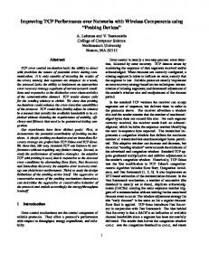
to hide losses from the wired network [10], by using for example an ARQ (Automatic Repeat Request) scheme to retransmit lost packets. Such a scenario is depicted in Figure 1. The IWF is located at the boundary between the CT system and the Internet and includes an IP router. Wireless hosts communicate via cellular links with their base stations, and base stations are connected via wired links to the IWF. A simple frame delivery service is provided between the IWF and the host for voice communications. The RLP is used to improve reliability and to encapsulate IP datagrams into link frames. By providing the standard IP services on top of the RLP, the wireless host can use any transport protocol, such as TCP, to communicate with other Internet hosts. Instead of mobile devices communicating with the Internet via a cellular circuit and appropriate RLP/IWF functionality, IP datagram services may be extended to the mobiles by sharing the CT link itself. CDPD offers such a service over unused cellular links, shared by the CDPD devices via a multi-access protocol [11]. When a mobile acquires the link, it sends or receives datagrams framed according to the CDPD RLP. These datagrams are processed by an IP router at the provider’s premises, which is attached to the Internet. CDPD was designed to coexist with analog CT systems, so its future is unclear in view of the proliferation of digital CT systems. However, its IP service model can be adapted to any CT circuit mode system. Current digital CT systems are based on either TDMA (GSM and IS-54) or CDMA (IS-95). They offer circuit mode data services terminating at the IWF, and non-transparent modes that insert an RLP between the IWF and the mobile. Their main characteristics are summarized in Table I. GSM (TDMA) full rate channels support user data rates (after discounting error recovery overhead) of 9.6 Kbps at average bit error rates of 10−3 . The non-transparent service is based on HDLC with 240 bit frames, including a 24 bit error detection CRC. To optimize use of the scarce wireless bandwidth the GSM RLP employs Selective Repeat ARQ with sequence numbers in the range [0, 61], instead of the simpler Go-Back-N. This RLP reduces the average bit error rate to 10−8 at the expense of variable throughput and delivery delays due to retransmissions [9]. This delay variability is on top of the long delays caused by the physical layer error recovery scheme that employs bit interleaving across multiple TDMA frame slots, regardless of RLP frame boundaries. Next generation GSM variants will offer enhanced data services and higher bandwidth by allocating multiple TDMA frame slots to individual users on demand. The IS-54 (TDMA) system supports 9.6 Kbps full rate links (after discounting error recovery overhead). The nontransparent service uses a sophisticated ARQ based RLP with sequence numbers in the range [0, 127] and 16 bit error detection CRCs in each 256 bit frame. Each frame acknowledges positively or negatively multiple sequentially numbered frames, reducing control overhead. This feedback not only indicates which frames have been received, but since the link preserves sequencing it also shows which frames have been lost. This is achieved by having the sender keep track of the order of frame (re)transmissions, so that when a frame is acknowledged, all unacknowledged frames transmitted before it can be assumed lost [10]. The effective throughput with this scheme is 7.8-8.2
4
PUBLISHED IN: IEEE NETWORK, VOLUME 13, NUMBER 4, 1999, PP. 55–63
TCP
TCP
IP
IP (router)
RLP Framing Physical
Wireless Host
IP
RLP Framing (relay) Physical
Physical
Framing
Internet
Physical
Base Station
IWF
Wired Host
Fig. 1. Connectivity between cellular links and the Internet
Kbps, with variable delays due to retransmissions. The IS-95 (CDMA) system supports 8.6 Kbps full rate data links using 172 data bit frames with a 1-2% frame error rate [2]. The non-transparent mode RLP uses 12 bit CRCs and sequence numbers in the range [0, 255]. A novel feature of this system is that network layer data packets are first encapsulated into variable size PPP frames (including 16 bit CRCs) and then segmented into fixed size RLP frames, with the reverse process taking place at the destination. This two level scheme combines the convenience of variable sized IP packets with the fast and efficient error recovery possible with fixed size RLP frames. The RLP uses only negative acknowledgments to reduce control overhead. Frames not received after a limited number of retransmissions are dropped. The reasoning is that a higher layer protocol such as TCP can provide, if required, additional recovery from the much smaller residual error rate. Since a complete PPP frame and its encapsulated packet are dropped if any of its RLP frames are missing, this scheme trades off packet loss for limited delay variance. The effective packet loss rate is around 10−4 at user data rates of 7.5-8 Kbps. Digital cordless systems combine the indoor environment and high bandwidth of wireless LANs with the circuit mode of cellular links. Emerging standards will allow equipment from different vendors to interoperate, enabling digital cordless devices to roam between base stations, thus forming a picocellular network. The small diameter of such cells means fewer devices sharing the frequency spectrum, i.e. more bandwidth available to each user. The CT2 standard supports a raw data rate of 32 Kbps and is mainly promoted for telepoint payphone services, where the mobile can only originate calls. An extended version, CT2+, offers full mobility management [1]. The DECT standard also offers 32 Kbps for raw data and is designed for picocellular applications by offering authorization support, mobility management and multiple link layers [1]. We do not further discuss these systems as their data services are unclear. Their high bandwidth and small coverage area however are important indicators of the future of picocellular CT systems. III. I NTERNET P ROTOCOLS AND W IRELESS L INKS A. Internet Transport Layer Protocols Transport layer protocols lie between user applications and the network. Although they offer user oriented services, their
design is based on assumptions about network characteristics. One choice offered on the Internet is UDP (User Datagram Protocol), essentially a thin layer over IP. UDP provides a connectionless best effort message delivery service, without flow, congestion or error control. Such facilities may be built on top of it, if needed, by higher layer protocols or applications. Besides offering nearly direct access to IP, UDP is also useful for LAN based applications: since wired LANs are extremely reliable and have plenty of bandwidth available, error and congestion control are not crucial. Wired long haul links have also been exhibiting decreasing error rates, due to the widespread use of optical fiber. The statistical multiplexing of increasing traffic loads over the Internet has replaced errors with congestion as the dominant loss factor. Congestion occurs when routers are overloaded with traffic that causes their queues to build up, resulting in increased delays and eventually packet loss. When such losses occur, the best remedy is to reduce the offered load so as to drain router queues and restore traffic to its long term average rate [12]. TCP (Transmission Control Protocol) is the other common transport protocol choice offered on the Internet, supporting many additional facilities compared to UDP. It provides a connection oriented reliable byte stream service that appears to applications similar to writing (reading) to (from) a sequential file. TCP also supports flow and congestion control, and segmentation and reassembly of the user data stream. TCP data segments are acknowledged by the receiver strictly in order. When arriving segments have a gap in their sequence, duplicate acknowledgments are generated for the last segment received in sequence. Losses are detected by the sender either by timing out while waiting for a transmitted segment to be acknowledged, or by a series of duplicate acknowledgments implying that the next segment in the sequence was lost in transit. TCP resembles a link layer protocol operating over the end-to-end datagram delivery service of IP. However, IP may reorder datagrams, so TCP cannot assume that all gaps in the sequence mean loss. Hence, TCP must receive multiple duplicate acknowledgments before assuming that a datagram was lost. During periods of inactivity or when acknowledgments are lost, TCP detects losses by the expiration of timers. Since Internet routing is dynamic, a retransmission timeout value is continuously estimated based on the averaged round trip times of previous data/acknowledgment pairs. A good estimate is very im-
PUBLISHED IN: IEEE NETWORK, VOLUME 13, NUMBER 4, 1999, PP. 55–63
System GSM IS-54 IS-95
Data Rate 9.6 Kbps 9.6 Kbps 8.6 Kbps
5
Non Transparent Mode Scheme Selective Repeat ARQ Frame Transmission Order ARQ Limited Retransmission ARQ
Access Scheme TDMA TDMA CDMA
TABLE I C ELLULAR SYSTEM CHARACTERISTICS
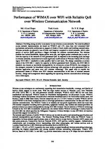
portant: large timeout values delay recovery after losses, while small values may cause timeouts to occur when acknowledgments are slightly delayed, even in the absence of loss. Since in wired links the dominant cause of losses is congestion, recent versions of TCP assume that all losses indicate congestion [12]. As a result losses cause, apart from retransmissions, the transmission rate of TCP to be reduced and then gradually increased, probing the network for the highest load that can be sustained without causing congestion. Figure 2 illustrates how TCP reacts to losses. TCP maintains an estimate of how much unacknowledged data can be outstanding in the network without causing congestion. The actual amount of outstanding data is limited by the minimum of this congestion window (for congestion control) and the receiver’s advertised window (for flow control). Initially, the congestion window is set to one segment and a slow start threshold is set to a large value. While below the threshold, each new acknowledgment causes the congestion window to increase by one, thus doubling after each round trip time, i.e. an exponential increase. This is the slow start phase. In the figure this increase stops after 4 round trip times when a timeout indicates that a segment was not acknowledged. Immediately the slow start threshold is set to half the value of the congestion window, the congestion window is set to a single segment, and the lost segment is retransmitted. Slow start again takes place until the threshold is reached in 3 more round trip times, allowing congested routers to drain their queues. Since congestion occurred at double the current window size, from there on the congestion window increases by a single segment for each round trip time, i.e. a linear increase. This is the congestion avoidance phase. When loss is detected by the arrival of duplicate acknowledgments instead of a timeout, indicating that subsequent segments have been received, newer TCP variants omit the slow start phase and (roughly) restart from the congestion avoidance phase, after recovering from the loss and halving the congestion window [13]. This reduces but does not eliminate the significant drop in throughput during losses. Not that clustered losses cause the congestion window and threshold to be reduced repeatedly, forcing the (slower) congestion avoidance phase to start from even smaller window sizes. B. Protocol Performance Over a Single Wireless Link The low error rate assumption of TCP, while reasonable for wired links, has disastrous results for wireless links. A representative WLAN, the WaveLAN described above, when transmitting UDP packets with 1400 bytes of user payload over an 85 foot distance suffers from an average frame error rate (FER)
of 1.55% [6]. These errors are clustered as in congestion losses and their rate is mainly influenced by the distance between hosts and the frame size. While distance is imposed by the operating environment, the frame size can be reduced to minimize the error rate. Reducing the frame size by 300 bytes halves the measured FER [6], as shown in Table II (see [6] for a two state error model that accurately reflects this behavior). The first column indicates the user payload in each frame and the second column the percentage of lost frames for that frame size. By encapsulating each UDP segment in one IP datagram and one WaveLAN frame, we have 48 bytes of header and trailer overhead added to each frame, so the percentage of overhead included in each frame increases with shorter frames, as shown in the third column of Table II. By combining the FER and overhead for each frame size we get the percentage of the bandwidth that is available for user data, shown in the fourth column of Table II. In this case, when reducing frame size the increase in overhead more than balances the scale. The available bandwidth is thus maximized with 1400 byte data segments at roughly 95% of link capacity, after discounting losses and overhead. For example, if we transmit 1400 byte segments (column 1), which become 1448 byte Ethernet frames, at a rate of 1.6 Mbps, the FER is 0.0155 (column 2) and the overhead factor is 48/1448 = 0.03315 (column 3). The bandwidth used for data is thus (1 − 0.0155) ∗ (1 − 0.03315) ∗ 1.6 = 1.523 Mbps, about 95% of the total bandwidth used (column 4). TCP normally achieves lower throughput than UDP, not only due to its extra 12 bytes of overhead per data segment (the difference between UDP and TCP header sizes), but also because reverse traffic (acknowledgments) must share the shared WLAN medium with forward (data) traffic. Another effect of sharing the link is transmission delays due to collisions. Our own measurements indicate that with the WaveLAN these collisions may sometimes go undetected, thus increasing the error rate visible to higher layers with bidirectional (TCP) traffic [7]. Also, host mobility increases error rates for this WLAN by about 30%, in the absence of handoffs [6]. Measurements of a TCP file transfer over a WaveLAN link using 1400 byte data segments revealed that the throughput achieved is only 1.25 Mbps out of the 1.6 Mbps available on the link [6], thus a throughput reduction of 22% is caused by only a 1.55% frame error rate. This is due to TCP frequently invoking congestion avoidance mechanisms that reduce its transmission rate, even though the losses are not due to congestion. If errors were uniformly distributed rather than clustered, throughput would be 1.51 Mbps [6], only 5.5% below the nominal rate, since TCP performs worse with losses clustered within one transmission window (see [14] for an analysis of TCP under multiple losses). Cellular links offer even less of their nominal bandwidth to
6
PUBLISHED IN: IEEE NETWORK, VOLUME 13, NUMBER 4, 1999, PP. 55–63
18
Congestion window Slow start threshold
Timeout Congestion window (segments)
16 14 12 10 8 6 4 2 0 0
2
4
6 8 10 Time (round trips)
12
14
16
Fig. 2. TCP congestion window behavior
User Payload (bytes) 500 800 1100 1400
Error Rate (%) 0.194 0.388 0.775 1.550
Overhead (%) 8.759 5.660 4.181 3.315
Available Bandwidth (%) 91.064 93.974 95.076 95.186
TABLE II W IRELESS LAN
PERFORMANCE
the user, due to their 1-2% FER [2], quite large for the short frames used. An IS-95 link transmitting at full rate uses 172 bit data frames, excluding link layer overhead. Since this is insufficient even for TCP and IP headers, the link layer segments IP datagrams into multiple frames. For comparison with the WLAN case above, a UDP packet with 1400 bytes of user payload and 28 bytes of UDP/IP overhead would be segmented into 68 link layer frames. Assuming independent frame errors and a FER of 1%, the probability that the datagram will make it across the link is 50.49%, while at a FER of 2% this probability drops to 25.31%. Frame errors are less bursty than bit errors in CT systems because bits from multiple frames are interleaved before transmission. After the receiver reorders the interleaved bits, error bursts are spread over multiple frames so that usually the embedded error correction code of each frame can recover its contents. This reduces FER and randomizes frame errors, avoiding audible speech degradation, but it adds considerable delay as multiple frames need to be received before reverse interleaving and decoding. For example, frame delivery delay on IS-95 is around 100ms. Reducing the datagram size again reduces FER at the expense of increasing header overhead. However, TCP overhead can be reduced to 3-5 bytes per datagram by employing header
(UDP)
compression, a technique appropriate for low bandwidth serial links [15]. This optimization is feasible only for the TCP/IP combination. Since CT systems use separate uplink and downlink channels, forward (data) and reverse (acknowledgment) traffic do not interfere as in the WLAN case. Rather surprisingly then, TCP offers potentially more bandwidth to the user than UDP in CT links, due to TCP header compression. Assuming full frame utilization, 5 byte compressed TCP/IP headers and a 2% frame error rate, Table III shows the percentage of total bandwidth that is available for user data, in the same format as Table II. Datagram size varies from 4 to 32 link layer frames, i.e. 81 to 683 data bytes (first column), and independent errors are assumed for simplicity (the datagram error rate is shown in the second column). Independent errors are a pessimistic assumption, since clustered errors would affect fewer datagrams, but reasonable in view of the physical layer interleaving. While the error rate increases with longer datagrams, the constant TCP/IP overhead becomes a smaller fraction of each datagram (third column). The available bandwidth (fourth column) is maximized with 81 byte datagrams, at about 87% of link capacity, as error rate dominates overhead in the calculations. As an example, when transmitting 81 byte data segments (column 1), i.e. 86 byte datagrams, the error
PUBLISHED IN: IEEE NETWORK, VOLUME 13, NUMBER 4, 1999, PP. 55–63
User Payload (bytes) 81 167 339 683
7
Error Rate (%) 7.763 14.924 27.620 47.612
Overhead (%) 5.814 2.907 1.453 0.727
Available Bandwidth (%) 86.874 82.603 71.328 52.008
TABLE III C ELLULAR LINK PERFORMANCE (TCP)
rate is (1 − 0.984 ) = 0.07763 since 4 link layer frames are used (column 2), and the overhead factor is 5/86 = 0.05814 (column 3). Since the total bandwidth of this system is 8.6 Kbps (one 172 bit frame every 20 ms), the user data rate is (1 − 0.07763) ∗ (1 − 0.05814) ∗ 8.6 = 7.47 Kbps, which is about 87% of the bandwidth used (column 4). Note that this assumes perfect error recovery (i.e. TCP never waits for a timeout and never retransmits correctly received data), which is far from true in practice. C. Protocol Performance Over Multiple Links We previously focused on paths composed of a single wireless link. When multiple wireless links are traversed, errors accumulate accordingly. This occurs when users of distinct CT or WLAN systems communicate via the wired infrastructure. Assuming that the behavior of the two wireless links is uncorrelated, the cumulative error rate for two WaveLAN links is 3.08% while for two CT links it is 14.92%, for the optimum cases in the preceding examples (1400 byte UDP and 85 byte TCP payloads, respectively). Increased losses mean more frequent invocations of TCP congestion avoidance algorithms. Reducing transmission rates due to mistaking wireless errors for congestion causes underutilization of the wireless link. CT links operating at around 10 Kbps are most likely the bottlenecks of end-to-end paths, thus underutilizing them means reduced end-to-end performance. In addition, CT links usually serve one user with few transport connections, so any unused bandwidth is usually wasted, even though the user is billed based on connection time. WLANs, despite their higher bandwidths, are also likely to be the bottlenecks of end-to-end paths, but given enough users on the shared medium the bandwidth released by one TCP connection may be used by others. Another problem with long paths is that TCP retransmissions must traverse the path from the sender until the wireless link again. If a single wireless link is located on the receiver’s end of the path, these retransmissions simply waste wired link bandwidth and delay recovery. If more than one link is wireless however, datagrams must be retransmitted over wireless links that were already crossed successfully, further reducing throughput. The combined effect of mistaking wireless losses for congestion and slow end-to-end recovery is more pronounced on longer paths that require large TCP windows to keep data flowing: when the TCP transmission window is reduced after losses are detected, the end-to-end path remains underutilized until the window grows back to its appropriate size, which takes more time for longer paths. When multiple losses occur during a single (large) window, TCP performance is further reduced.
Table IV shows the performance of TCP over a single hop (LAN) versus a multihop (WAN) path (the results are taken from [16]), in absolute terms and as a percentage of the nominal bandwidth. One end of the path is on a wireless LAN transmitting 1400 byte frames with a FER of about 2.3%, a situation slightly worse than the one described earlier. The nominal bandwidths hold in the absence of any congestion or wireless link losses, while the TCP throughput numbers are based on simulating errors using a simple independent error model. The difference between the two TCP variants is that the improved protocol can recover from more than one error during a single error recovery period without a timeout. As a result, in the high error rate wireless link, the improved variant achieves higher throughput and depicts smaller differences between the LAN and WAN cases. In all cases, the throughput degradation is at least 10 times the FER. IV. P ERFORMANCE E NHANCEMENTS FOR I NTERNET P ROTOCOLS A. Approaches at the Transport Layer Most of the research on Internet protocol performance over wireless links has focused on TCP, the most commonly used transport protocol on the Internet. The main cause of the reported problems is the TCP assumption that all losses are due to congestion, so that loss detection triggers congestion avoidance procedures. The frequent losses seen on wireless systems, whether due to wireless errors or pauses during handoffs, cause TCP to underutilize the bandwidth starved wireless links, dramatically reducing end-to-end performance. Longer paths further delay end-to-end recovery, aggravating these performance problems. A direct way to improve TCP performance is to modify TCP itself, since it is TCP assumptions that cause the problems. In addition, TCP requires only the two communicating peers to upgrade their software in order to take advantage of improvements. Solutions depend on the cause of losses: handoffs or errors. During handoffs connectivity is temporarily lost and a timeout may be required before recovery can be initiated. To avoid long pauses after handoffs, one approach is to invoke fast retransmission right after a handoff completes, instead of waiting for a timeout. This requires signaling to notify the transport layer about handoff completion [17]. Invoking full congestion recovery procedures after every handoff still reduces throughput, so an alternative is to attempt to detect whether loss is due to mobility or congestion by exploiting mobility hints from lower layers [18]. If the loss is due to congestion, both slow
8
PUBLISHED IN: IEEE NETWORK, VOLUME 13, NUMBER 4, 1999, PP. 55–63
LAN WAN
Nominal 1.5 Mbps 1.35 Mbps
Simple TCP 0.70 Mbps 46.66% 0.31 Mbps 22.96%
Improved TCP 0.89 Mbps 59.33% 0.76 Mbps 56.29%
TABLE IV T HROUGHPUT OF LAN AND WAN CONNECTIONS (TCP)
start and congestion avoidance are used. If the loss is due to mobility, only slow start is used for faster recovery. Unlike handoffs where congestion avoidance is needed to probe the state of the new link, with losses due to errors we should skip congestion avoidance completely. Since these losses are local, end-to-end retransmissions unnecessarily delay recovery. One way to improve error recovery is to split TCP connections at pivot points, i.e. those routers on the path connected to both wireless and wired links. One instance of TCP executes over each wired part while either another instance of TCP or another protocol executes over each wireless part [19], [20]. These segments are bridged by software agents at each pivot point that also translate between protocols, if required. As a result, losses at wireless segments do not trigger end-toend recovery. When TCP is used over the wireless segments, it can recover fast due to the short paths involved. Alternatively, a transport protocol with faster recovery mechanisms may be substituted [20]. The ideal scenario in this case is a path with wireless endpoints, where the pivot points are the routers connecting the wireless network to the Internet. Only the pivot points and (maybe) the wireless hosts need software upgrades. Handoffs in these schemes change the endpoint but not the pivot point, so that the agent at the pivot can establish new connections and speed up recovery after a handoff. For UDP, datagrams lost during communications pauses can be retransmitted when connectivity is re-established, as in M-UDP [21]. For TCP, the pivot agent can also choke the remote sender by closing the advertised window, as in M-TCP [22]. This causes the sender to go into persist mode, during which it periodically probes the receiver’s window while freezing all pending timers. However, shrinking the advertised window violates TCP guidelines. TCP modifications are not perfect solutions. Schemes that only deal with handoff problems modify the transport layer only at the endpoints, but they still face performance degradation due to wireless errors. To detect handoffs, coupling is introduced between layers to solve an isolated and localized problem, with improvements that are applicable only to TCP. Split (or indirect) TCP approaches [19], [20] deal with both mobility and link errors, but they require modifications both at the endpoints and at the pivot points, the latter generally being beyond user control. New transport protocols compatible with TCP are needed to maximize performance over wireless segments, although the split connection idea is applicable to any protocol. The agents at the pivot points are complex: they must translate semantics and synchronize connections despite communications errors and pauses. Performance is questionable for wireless segments not at path ends or for multiple link wireless segments. Finally, the end-to-end semantics of the transport layer may be violated, thus applications that need end-to-end reliability must use additional protocols above TCP. Unfortu-
nately, applications do not know that the end-to-end semantics are violated. B. Approaches below the Transport Layer The main alternative to modifying TCP or other end-to-end protocols is to modify the link layer protocol that operates over the wireless link so as to hide losses using local recovery mechanisms. CT systems offer non-transparent RLPs that enhance link reliability [2], [9], [10] with this exact goal in mind. Another approach, applicable to both WLANs and CT systems, is adding some link layer functionality to IP, to take care of local recovery [23]. IP datagrams carrying TCP data are buffered at the hosts that transmit them over wireless links and are retransmitted if they are not acknowledged within a short period of time or if duplicate acknowledgments for previous data are received. The local error recovery module snoops on all IP datagrams to gather TCP data and acknowledgment information. Buffered TCP data that need to be retransmitted are inserted into the data stream transparently to the receivers. By leveraging existing TCP messages this mechanism avoids additional control exchanges and simplifies integration with TCP. Conceptually, this is a link layer mechanism, as it involves single link error recovery. Interestingly, employing TCP acknowledgments for feedback, besides violating protocol layering, causes this approach to work only in the direction towards the wireless host. In this direction TCP acknowledgments are received at the wired endpoint after a one hop delay only, and retransmissions may be made before timers expire at the other end of the end-to-end path. In the reverse direction, TCP acknowledgments are returned after the round trip delay for the whole path has nearly elapsed, thus the wireless host cannot retransmit lost segments soon enough. To make retransmission effective in that direction, local control exchanges are needed (as required by protocol layering). This is also the case for wireless links that are not at the edges of end-to-end paths, where both sides need link layer control exchanges to initiate retransmissions on time. Overall, this local recovery scheme performs better than split transport layer schemes under wireless link errors [16], without violating transport layer semantics, although it violates protocol layering. The advantages of TCP and link layer coupling are reduced link layer overhead and avoidance of conflicts between local and TCP retransmissions [3], but the scheme will require modifications whenever TCP mechanisms are modified, and does not work for any other protocols. CT system RLPs on the other hand, avoid layering violations, but run the risk of retransmitting data that the transport layer will retransmit anyway, hence the approach of the IS-95 RLP of limited recovery [2]. In addition, they may do more than
PUBLISHED IN: IEEE NETWORK, VOLUME 13, NUMBER 4, 1999, PP. 55–63
what is required for applications that do not require complete reliability. Link layer schemes in general have the advantage over end-to-end schemes of working at the local level, with intimate knowledge of the underlying media, and low round trip delays that allow fast recovery, although they cannot deal with handoffs, where multiple links are involved. The problem is how much to enhance the underlying link, without getting in the way of higher layers. The goal is to offer adequate recovery to ease the task of reliable transports and to allow the realistic operation of unreliable transports, which assume only rare losses. Even if vendors supply fine tuned link layer protocols with their devices, it is hard to design a single protocol that can cater to the needs of multiple transport layers and applications. V. T HE F UTURE : C HALLENGES AND O PPORTUNITIES
9
link. Adapting to these link specific variations is much easier locally, at the link layer, where the peculiarities of each medium are known. Second, medium term performance variations will be caused by handoffs between different technologies (picocellular, cellular and macrocellular). These handoffs will dramatically change the performance parameters of the wireless part of the end-to-end path, as each type of link will have its own characteristics. Adapting to such variations is probably only feasible at an end-to-end layer. Since handoffs take place between two separate links, dealing with handoff outages is not a local task, although the link layer could help by providing information to higher layers, such as notifications of handoffs and disconnections or current link properties after a vertical handoff. Hierarchical systems illustrate how similar problems (horizontal and vertical handoffs) with different parameters may be best treated at distinct layers.
A. Wireless System Evolution One of the most attractive characteristics of wireless systems is that they enable mobility. Cellular systems allow efficient sharing of the frequency spectrum via reuse and offer wide area mobility with reasonable power requirements [1]. Since each cell is connected to other networks via its own base station, mobility between cells implies a need for handoffs of mobile devices between base stations. These handoffs cause pauses in communication while the mobile completes base station changes. When data are lost during handoffs, reliable Internet protocols such as TCP may be tricked into mistaking these losses for congestion [17]; this is the case even if data are not really lost but only delayed. Some future cellular systems are expected to employ smaller cells (picocells) in order to offer higher data rates and support more users at the same time. Picocells, due to their smaller area, will require a dense mesh of base stations. This cost will only be justifiable within buildings or densely populated areas. Thus, current cellular systems with standard sized cells will still provide lower bandwidth coverage in areas with fewer users, while sparsely populated areas that do not warrant the cost of terrestrial cellular infrastructure will be covered by satellite systems. The large area under a satellite beam will then form a macrocell. In low orbit satellite systems handoffs will still occur, but mostly due to satellite rather than user movement. This will give rise to a hierarchical cell structure [24], as depicted in Figure 3: higher level cells are overlaid in areas with more users by multiple lower level cells. Users can use the highest bandwidth system available in each location and move from cell to cell within the same system (performing horizontal handoffs, as in existing cellular systems), or from one system to another (performing new style vertical handoffs) depending on coverage. Hierarchical systems will introduce challenges due to additional handoff induced problems. In the picocells, handoff frequency will increase, and since the per user bandwidth will be higher, more data will potentially be lost during handoffs, urging for faster handoffs and fast, localized, recovery. In parallel, since handoffs will be possible between different systems, connections will face two levels of link performance variability. First, short term performance variations will be caused by environmental changes such as fading, in the same manner as today, with details depending on the technology used at each
B. Goals for Protocol Evolution If we examine the performance problems of existing protocols and the shortcomings of proposed enhancements for wireless links, a few goals for further research emerge. • Masking wireless errors with non-transparent RLPs is not adequate for all types of transport protocols and applications. For example, UDP based real time applications typically prefer sending new packets to retransmitting old ones. Similarly, transport layer modifications, despite using the most appropriate mechanism for any given transport protocol, are protocol specific and not easily extensible to hierarchical cellular systems. We thus need a multiprotocol approach to wireless link enhancements. • While mobility problems cannot be dealt with at the link layer (whose scope is isolated links), wireless link losses can be efficiently recovered from using local mechanisms [16]. Besides handling handoff pauses, higher layers will have to adapt to the medium term link variabilities caused by (vertical) handoffs to different networks in hierarchical cellular systems. Thus we need to deal with each wireless link problem at the appropriate layer. • Since applications have varying requirements, multiple transport layers should be supported on the Internet without having to worry about the details of each specific link. Isolating transport layer protocols from link peculiarities can be achieved by link layer protocols that support flexible and general services rather than specific transport protocols. Thus protocol layering and isolation should be adhered to during design. • The proliferation of wireless links will eventually cause many existing protocols to review their design assumptions and modify their mechanisms. New protocols may also emerge that are more flexible in dealing with wireless links and mobility, by exploiting adaptive mechanisms. Such protocols would be able to exploit advanced link layer services in order to offer enhanced services to their own users. Thus lower layer protocols could provide functionality to support future higher layer needs. In our view, neither link layer nor transport layer approaches are sufficient by themselves to solve the problems presented.
10
PUBLISHED IN: IEEE NETWORK, VOLUME 13, NUMBER 4, 1999, PP. 55–63
Macrocell (>100 km)
Satellite Cellular
Cell (1-100 km)
Terrestrial Cellular
Picocell (