50 - ARIMA–Numéro spécial CARI'06 – Volume 8 – 2008. 1. Introduction. In the network domain, protocol implementations must be tested to ensure that they.
Interoperability Test Generation: Formal Definitions and Algorithm Alexandra DESMOULIN — César VIHO IRISA/Université de Rennes I Campus de Beaulieu 35042 Rennes Cedex, FRANCE {Alexandra.Desmoulin,Cesar.Viho}@irisa.fr
RÉSUMÉ. Dans le contexte des protocoles réseaux, le test d’interopérabilité est utilisé pour vérifier si deux (ou plus) implémentations communiquent correctement tout en fournissant les services décrits dans les spécifications correspondantes. Le but de cet article est de fournir une méthode pour la génération de tests d’interopérabilité basée sur une définition formelle de la notion d’interopérabilité. Contrairement aux travaux précédents, cette étude prend en compte les blocages des implémentations qui peuvent être observés durant un test d’interopérabilité. Ceci est réalisé via la notion de critères d’interopérabilité, qui donnent des définitions formelles des notions d’interopérabilité existantes. Il est tout d’abord prouvé que la gestion des blocages améliore la détection de la noninteropérabilité. L’équivalence de deux des critères est aussi prouvée permettant l’introduction d’une nouvelle méthode de génération de tests d’interopérabilité. Cette méthode permet d’éviter le problème d’explosion combinatoire du nombre d’états que rencontrent les approches classiques. ABSTRACT. In the context of network protocols, interoperability testing is used to verify that two (or more) implementations communicate correctly while providing the services described in their respective specifications. This study is aimed at providing a method for interoperability test generation based on formal definitions. Contrary to previous works, this study takes into account quiescence of implementations that may occur during interoperability testing. This is done through the notion of interoperability criteria that give formal definitions of the different existing pragmatic interoperability notions. It is first proved that quiescence management improves non-interoperability detection. Two of these interoperability criteria are proved equivalent leading to a new method for interoperability test generation. This method avoids the well-known state explosion problem that may occur when using existing classical approaches. MOTS-CLÉS : Interopérabilité, test, critère, génération de tests, blocage KEYWORDS : Interoperability, test, criterion, test generation, quiescence
Volume 8 – 2008, pages 49 à 63 – ARIMA–Numéro spécial CARI’06
50 - ARIMA–Numéro spécial CARI’06 – Volume 8 – 2008
1. Introduction In the network domain, protocol implementations must be tested to ensure that they will be working in an operational environment. They must be able both to communicate with other protocol implementations and to offer the service described in their specification. Differents kinds of tests are used to verify that implementations are able to work "correctly". Among these tests, functional tests are used to verify the external behavior of protocol implementations. These tests consider an implementation as a black-box. This means that testers only knows the implementation via events executed on its interfaces. Among these functional tests, conformance testing is a kind of test that determines to what extent a single implementation of a standard conforms to its requirements. Conformance testing is precisely characterized with testing architectures, a standardized framework ISO/IEC IS9646 [1], formal definitions [2] and tools for generating automatically tests [3, 4]. In this paper, we consider another kind of functional testing called interoperability testing. Its objectives are to verify both that different implementations can communicate correctly and that they are provided the service described in their respective specification while interacting. This test is still considered as a pragmatic issue. Indeed, it requires configurations of tested systems, specific parameterizations, etc. Results obtained may depend on these operations. Nevertheless, the same arguments applied to conformance testing, but studies on formal approach for conformance testing has increased the knowledge in this area. Despite a large literature on the interest of providing a formal approach for interoperability testing (for example [5, 6]), only few tentatives of formal definitions or automatic method of interoperability test generation have been proposed [7, 8, 9]. In this study, we consider a context of interoperability called one-to-one context. This context is used to test the interoperability between two systems. It is the interoperability testing context the most used in practice to test, either the interoperability of two implementations or the interoperability of one implementation with another system (seen as the second implementation) composed of different entities. The aims of the study presented here are double. First, we give formal definitions of the one-to-one interoperability notion. Contrary to a previous work [10], these definitions manage quiescence. They are called interoperability criteria (or iop criteria in the following). An interoperability criterion formally describes conditions under which different implementations (two in this study) can be considered interoperable. The second contribution of this work is a new method to generate automatically interoperability test cases. It uses a theorem proving the equivalence between two iop criteria and avoids the construction of a model of the specification interaction that may lead to the well-known state-explosion problem [11]. The paper is structured as follows. Section 2 gives the considered interoperability testing architectures. Models and the formal background used in this paper are in Section 3. The iop criteria are defined in Section 4. In Section 5, the proposed method and associated algorithms for interoperability test case generation are described. Results obtained are illustrated with a simple example. Conclusion and future work are in section 6.
ARIMA–Numéro spécial CARI’06
Interoperability test generation 51
2. One-to-one interoperability testing context Interoperability testing is a kind of test used to verify that protocol implementations are able to communicate correctly while providing the services described in their respective specification. Two contexts can be differentiated for interoperability testing: one-toone context (interaction of exactly two implementations) and a more general situation with ( ) implementations. This study focus on the one-to-one context. Moreover, in interoperability testing, each implementation is seen as a black-box. This means that testers only know an implementation from its interaction with the environment or with other systems, thus from the events that are executed on the interfaces of the implementation.
����
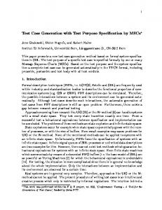
In this study, we consider a System Under Test (SUT) composed of two implementations under test (IUT for short). The general testing architecture of this one-to-one interoperability context is represented in figure 1. UT1
UT2
UP1 TS (Test System)
T1
UI1
UP2 LT1
LT2
LP1
LP2
SUT
IUT1 LI1
T2
UI2 IUT2 LI2
Figure 1. Interoperability testing architecture
��� � ���
In interoperability context, each of the IUTs has two kinds of interfaces. The lower are the interfaces used for the interaction of the two IUTs. These interfaces interfaces are only observable but not controllable.It means that a tester ( ) connected to such interfaces can only observe the events but not send stimuli to these interfaces. The upper interfaces are the interfaces through which the IUT communicates with its environment. They are observable and also controllable by the tester .
�� �� � �
In some situations as testing of embedded systems (or for confidentiality reasons), certain interfaces may not be accessible for the testers. Thus, different interoperability testing architectures can be distinguished depending on the access to the interfaces. For example, the interoperability testing architecture is called lower (resp. upper) if only the lower interfaces (resp. the upper interfaces) are accessible and total if both kinds of interfaces are accessible. It is called unilateral if only the interfaces of one IUT (on the two interacting IUTs) are accessible, bilateral if the interfaces of both IUTs are accessible but separately, or global if the interfaces of both IUTs are accessible with a global view. The interaction between the two IUTs is asynchronous (cf. Section 3.2). This is generally modeled by an input FIFO queue for each lower interface.
ARIMA–Numéro spécial CARI’06
52 ARIMA–Numéro spécial CARI’06 – Volume 8 – 2008
3. Formal background This section describes the different formal notations used in the following of the paper.
3.1. IOLTS model We use IOLTS (Input-Output Labeled Transition System) [12] to model specifications. As usual in the black-box testing context (tests based on what is observed on the interfaces of the IUTs), implementations are also modeled, even though their behaviour are normally unknown. They are also represented by an IOLTS. Definition 3.1 An IOLTS is a tuple M = ���� , ��� , ��� , � � where � � � � is the set of states of the system and �� is the initial state. � � � � denotes the set of observable (input and/or output) events on the system interfaces. � � ����� stands for an input and ��� � for an output where � is the interface on which the event is executed and � the message. � is the transition relation, where �"� ! � � denotes an � ��� � ��� �� ��� � � � � % '& or ( *),+-), '& � � � . internal event. A transition is noted $# �
can be decomposed as follow: � M . � M/ � � M0 , where � M/ (resp. � M0 ) is the set of messages exchanged on the upper (resp. lower) interface. � M can also be decomposed to distinguish input ( � M1 ) and output ( � M2 ) messages. Let us consider a state , an IOLTS 3 and an event 4 � � � : � 65'7*8:9'; � is the set of observable events (executed on the interfaces of 3 ) from the state and > @3A)B= the set of observable events for the system 3 after the trace = . � In the same way, C?D�E:�3A),= (resp. GFH�3A),= ) is the set of possible outputs (resp. inputs) for 3 after the trace = . � Considering a link I between the lower interfaces I of 3 and IKJ of 3 J , the mirror L4 of an event 4 is defined by 4 L =I � 7 if 4 = IKJ � 7 and 4 L = I � 7 if 4 = IKJ � 7 . �
M
�
��
�
�
δ
δ
S1
S2
0
0
U?A
l?a
l?b 1
U!R
l!c δ l?r 3
5
l!d
U!N
l!a
U!R δ
l?c l!r
l?n 5
Figure 2. Specifications MON and
ARIMA–Numéro spécial CARI’06
MQP
l!b δ
3
2
2 4
1
l?d 4
l!n 6
U!N
Interoperability test generation
53
Figure 2 gives an example of two specifications using the IOLTS model. �� corresponds to a request from the upper layer of ��� . Then, ��� and ��� may exchange some messages via their lower layer. The resulting response to the request can be either positive (output on the upper interface � � ) or negative (output � ).
Quiescence: Three situations can lead to quiescence of a system : deadlock (a state after which no event is possible), outputlock (a state after which only transitions labeled with input exist) and livelock (a loop of internal events). Quiescence is modeled by for an IOLTS 3 or � for an IOLTS 3 . It is treated as an observable output event and observed practically using timers. The IOLTS obtained after calculating quiescence is called suspensive IOLTS [2] and noted � @3 . On the examples of Figure 2, quiescence is possible and modeled on these specifications (see in states and of � � , , and � of ��� ).
�
�
�
3.2. Operations: interaction and projection Interoperability testing concerns the interaction of two or more implementations. To provide a formal definition of interoperability considering the interoperability testing architecture of Figure 1, we need to model the asynchronous interaction of two entities. For two IOLTS 3�� and 3�� , this interaction is noted 3������ 3�� . This operation is calculated in two steps. First, � @3�� and � @3�� are transformed into IOLTS representing their behaviour in an asynchronous environment modeled with FIFO queues as in [12]. Then, these two IOLTS are composed to obtain 3 � � � 3 � . This operation preserve quiescence and � (resp. ) corresponds to quiescence of 3 (resp. of the two IOLTS).
�
In interoperability testing, we usually need to observe some specific events of an IUT. The IUT, reduced to the expected messages, can be obtained by a projection of the IOLTS representing the whole behavior of the implementation on a set (called � in the following and used to select the expected events). This is noted by 3���� and is obtained by hiding events (replacing by � -transitions) that do not belong to X, followed by determinization.
3.3. Implementation model As usual in the black-box testing context, we need to model implementations, even if their behaviors are unknown. As described in figure 1, the two IUTs interact asynchronously and testers are connected to their interfaces. These testers can observe messages exchanged via lower interfaces. But they can not differentiate a message that was sent to the lower interfaces of one of the IUTs to a message actually received by this IUT. Thus, testers can only know which messages were sent by the interacting IUT. To model this situation, we choose to complete the model of an IUT with inputs corresponding to the output alphabet (lower interfaces) of the other IUT specification. These transitions lead the IOLTS into an error state. It is a deadlock state. On the upper interfaces, the IUT interacts directly with the tester (like in a conformance testing context). Thus, for events on the upper interfaces, the input-completion of the IUT corresponds to the input completion made for conformance testing. In the following, the IUT are considered iop-input completed with quiescence modeled.
3.4. Specification model As we are concerned by interoperability testing, the considered specifications must allow interaction. We call this property the interoperability specification compatibility
ARIMA–Numéro spécial CARI’06
54 ARIMA–Numéro spécial CARI’06 – Volume 8 – 2008
property (iop-compatibility property for short). Two specifications are iop-compatible iff, for each possible output on the interfaces used for the interaction after any trace of the interaction, the corresponding input is foreseen in the other specification. In a formal way : O= � 65'7*8:9';< � � � � � � )�O=�� 7�� =O& � 65'7*8:9';< � � � � � � , 7 � C?D�E���� � � � � � � ),= , . � ��� � � , ��� such that . 7 L . =O& In some situations (underspecification of input actions particularly), the two specifications need to be completed to verify this property. It is done by adding transitions leading to an error trap state and labeled with the inputs corresponding to messages that can be sent by the interacting entity (input � added in FH � J )B=�� � J if � L � C?D�E 0 � B)B=��G� ). Indeed, this method considers the reception of an unspecified input as an error. This is the most common definition of unspecified inputs in network protocols. In the following, we will consider that specifications are iop-compatible.
�
�
�
�
�
4. Interoperability criteria According to the different possible testing architecture (see Section 2), different notions of interoperability can be used [10]. In Section 4.1, we introduce interoperability formal definitions called interoperability (iop) criteria. An interoperability criterion formally describes the conditions that two IUTs (in the one-to-one context) must satisfy in order to be considered interoperable. Thanks to quiescence management [13], these iop criteria detect more non-interoperability situations than the “interoperability relations” defined in [10]. Moreover, in Section 4.2, we prove the equivalence -in terms of noninteroperability detection- between the most commonly used in practice iop criterion �� ��� and the so called bilateral iop criterion �� ��� .
4.1. Definitions of the interoperability criteria We will describe here iop criteria considering events on both kinds of interfaces. In the same way, iop criteria considering only lower (or only upper) interfaces can be defined using projection on the considered interfaces. The unilateral iop criterion focus on one of the IUTs during its interaction with the other implementation. This criterion is in the definition 4.1.
� �
�
Definition 4.1 (Unilateral iop criterion �� � / ) Let � , � two IUTs implementing respectively � � , � � . � �� = � � 65'7*8:9';


![Juniper / Cisco Interoperability Cookbook - Network Test [PDF]](https://m.moam.info/img/260x300/juniper-cisco-interoperability-cookbook-network-te_647ad3c6098a9e0f308b45a0.jpg)