33rd International Symposium on Automation and Robotics in Construction (ISARC 2016)
Interoperability with IFC in the automated rebar fabrication Maciel, Alex R. a and Corrêa, Fabiano R.b Escola Politécnica, University of Sao Paulo, Brazil E-mail: a
[email protected] , b
[email protected] Abstract – Some problems of efficiency in the cut and bent rebar supply chain is related to stakeholder’s interaction and the flow of information between designers, constructors and rebar fabricator. In the actual process, distinctive standards are used for exchange of information between design and fabrication. The BVBS format represents a standard widely used for automated cut and bent rebar production while the Industry Foundation Classes (IFC) aims to become the standard for exchange in the AEC industry with the use of Building Information Modeling (BIM). This study aims to explore the use of IFC schema to enable an effective integration of the rebar fabrication process with the BIM workflow, improving data exchange and reducing the need for manual intervention. Initially, the requirements for exchanging reinforcement data laid down in BVBS standard are reviewed. Key requirements to a digital interface are parsed across IFC schema specification in order to ascertain how this information are mapped on IFC. The current way for geometric representation of reinforcing bars, used by some structural BIM tools to export IFC files, is reviewed, in addition with new entities release in IFC4. Some recommendations are provided for improving the interoperability efficiency. Keywords – BIM; IFC; Reinforcement bar; Automated bending machine;
1
Introduction
Several authors [1][2][3][4] have studied the interaction between agents involved in the supply chain of reinforcement bars. Although some activities, such as raw material supply, design of required reinforcement and on-site assembly, have a clear actor designated to that role, other activities such as detailing, reckoning and fabrication can be performed by different actors depending of particular supply chain configuration [1].
In the Brazilian cut & bent rebar supply chain, both the design and rebar's detailing activities are performed by the engineering firm and delivered to the constructor or General Contractor (GC) [2]. This configuration features a high dependence among stakeholder's, particularly for the fabricator [1] that carries out the reckoning, produces and deliver the rebar goods to construction site based on the drawings and order form handed in by GC. It is crucial that they received accurate information [2]. The main source of problems in the Brazilian case [4] is related to failures on information flow and communication between the agents involved, especially due to: a) imprecise order and b) poor quality of structural design. The use of Building Information Modeling (BIM) contributes to improving the quality and integrity of the process. The production of detailing drawings [5] directly from 3D coordinated reinforcement models (with bidirectional associativity) can reduce errors and considerably enhance its consistency. To that end, it is necessary to establish how the information could be exchanged from BIM design environment and the standard accepted by the automated process of cut and bend rebar. Currently, the main among the available formats used in cut and bent rebar for Cast-in-place (CIP) is the BVBS standard, allowing a digital data exchange with CAM controlled bending machine or Production Planning and Scheduling (PPS) software. However, it is limited to geometry and some references between detailing and placing rebar drawings, and do not allow the addition of information under the contractor's responsibility relating to the order and delivery date. Another point to be considered is the feasibility of this interface, which demands synergy between the engineering firm and fabricator. Due to the supply chain configuration, such as Brazilian case, these agents does not collaborate directly. This link is effected through the general contractor and he acts as an intermediate. The importance of improvement of existing interfaces or development of new standards is highlighted by [5] in order to reduce the need for manual intervention by the
Building Information Modeling (BIM)
fabricator. However, it must also consider interfaces that allow the reuse of information created along the design, detailing, planning and procurement phases and enables the collaboration between all stakeholders. Nowadays, the improvement of existing standards maintaining compatibility with existing cut and bent reinforcement industrial plants can be considered a suitable choice to be held alongside the development of new standards. For being a consolidated and non-proprietary format for information exchange in the AEC industry, the use of the Industry Foundation Classes (IFC) appears as a good option alongside rebar supply chain. In this study we analyzed the requirements for exchanging reinforcement data laid down in BVBS standard in order to ascertain how this information are mapped on IFC schema. There is a particular interest in the geometric representation of reinforcing bars, and we provide a comparison of forms present in some structural BIM tools to export IFC files, in addition with the reviewed new entities released in IFC4.
2
Design-production digital interface
Although the CAD-CAM integration have been in use for several years, the majority of standards and file formats have been developed considering a CAD context focused on bending patterns based on 2D drawings Error! Reference source not found.. This solution is effective especially when both detailing and production are under fabricator's control as in the United States. Otherwise, it requires a smooth communication among the players. Table 1. List of some standard files formats used for digital interface File format .abs
proprietary while others are created jointly by the cutting and bending rebar supply chain stakeholders. Amid the available formats the BVBS standard represent the main used on automation of cut and bent rebar manufacture for Cast-in-Place industry. ProgressXML and Unitechnik standards are widely used in precast industry, generally for production of precast wall panels and floor slab. Some BIM authoring tools have native support for these standards, while others require a third-party plugin to accomplish the design-production digital interface.
3
The BundesVereinigung der BauSoftwarehäuser standard (BVBS) [6] was developed in consensus by bending machine factories, construction software companies, reinforcement bending works, steel producers and academic institutions to assist the exchange of information between rebar detailing software and CNC controlled bending machines or PPS software without manual intervention. The BVBS specification features a data structure from the designer's perspective regardless of the fabrication machine which will be used and may also be understandable without authoring CAD/BIM tool. The reinforcement data are exchanged through a ASCII encoded text file and, as other CAD-CAM formats, BVBS is focused on 2D drawings. These files are composed by a data string divided into blocks, and preceded by a recognition code used to set the shape type group, which can be: two-dimensional rebar (BF2D), three-dimensional rebar (BF3D), spiral links (BFWE), mesh (BFMA) or lattice girders (BFGT). The recognition code also enables the machine to check if it will be able to produce the specified shape. The blocks in the file are arranged in the following order:
Name
Developer
BVBS
BundesVereinigung der BauSoftwarehäuser E.V.
ProgressXML
Progress Maschinen & Automation AG.
.pxml
2.
Unitechnik 7.0
Unitechnik Systems GmbH
.uxml
3.
Unitechnik 6.1
Unitechnik Systems GmbH
.cam
Rebar Data Exchange
Applied Systems Associates, Inc. (aSa)
.rdx
There is a variety of standards and files formats on the market, which allows the transcription of the information contained in the reinforcement detailing design in a digital format, as shown in Table 1. Some formats are
BVBS interface
1.
4. 5. 6.
Header block (H): provides data about identification and characteristics of the bar; Geometry block (G): describes the rebar’s shape bending geometry; Chair mesh block (A): defines the positions of the chair mesh in relation to bars. Bar block (X/Y): used only to mesh for define a diameter, bar origins and length; Private block: used for project or other internal data; Checksum block (C): for a checksum value.
Besides being a standard widely used in rebar's Castin-Place industry, the BVBS choice was held because it provides the data required by CNC controlled bending machine and can be used either directly at machine via USB or via barcode as a mass production workflow, via PPS software.
33rd International Symposium on Automation and Robotics in Construction (ISARC 2016)
Although this standard encompasses a wide variety of reinforcements types like spiral links, standardized meshes or engineered meshes, this article focused only on 2D and 3D reinforcement bars, and in the following sections the header and geometric blocks will be explored in more details.
3.1
Header block requirements
The requirement of the BVBS header block can be split essentially into three groups of information containing:
Identification and document reference: project number (j), drawing number (r) and revision number index (i); Material and rebar properties: steel grade (g), bar diameter (d) and bending diameter (s); Quantity Sets: bar length (l), item quantity (n), weight per bar item (e);
3.2
Geometric block requirements
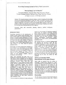
The coordinate system adopted by BVBS to describe the reinforcement bar geometry is set according to the shape group. While the BF2D (2D rebar) uses polar coordinate, the BF3D (3D rebar) is described in Cartesian coordinates. The measuring of shape dimensions is based on external length, similarly to the way predicted by some detailing standards as American ACI 315 [7], British BS 8666 [8] or European ISO 3766 [9]. BF2D geometry is described by the leg length (l) and subsequently by angle of the following bend (w). Each bend is determined by the bending diameter indicated in the header block and remains unique for all transitions. In case where distinctive bending diameters are needed, the radius of the bent element (r) must be set on the geometric block. For defining the BF3D geometry the coordinates of the bar's vertex (X,Y,Z) shall be provided. Figure 1 illustrates the BVBS specification for a twodimensional reinforcement bar.
Figure 1. Example of a two-dimensional reinforcement bar (BF2D) according to BVBS specification [6]
4
Interoperability with IFC
Since 2013, the Industry Foundation Classes (IFC) is a ISO standard (ISO 16739:2013) proposed by buildingSMART, and currently is in its IFC4 Add. 1 [10] version. It is a data schema that encodes information related to the entire lifecycle of a building. In its data architecture, there is a layer of data with many different discipline domains including the Structural Elements Domain, where most of the entities necessary to the workflow described here are modelled. From the 17 entities included in structural elements domain, 8 are new entities in IFC4, and other 6 were changed following the difference in conceptual modelling proposed by this new version of IFC. It
appears to be advocating the use of object types for attribute specifications instead of using the very instance of the object entity, which is a positive change. The reinforcement of a concrete structural element can be defined in multiple ways when relied upon the production and assembly hierarchy [11] [12]: a) individual bars; b) a set of identical bars distributed on a row pattern (e.g. stirrup) or a group of rebar with same function; or c) a rebar cage. The way how the reinforcement will be represented in the IFC schema also depend on the way they were defined. Information related to rebar's geometry and properties are defined at object-type level by means of IfcReinforcingBarType entity. Through the mapped representation associated with a single or multiple
Building Information Modeling (BIM)
IfcMappedItem, individual rebars or sets of same rebars can be represented in the object-level occurrence as shown in Figure 2 . The IfcReinforcingBar (attributes changed in IFC4) and IfcReinforcingBarType (new in IFC4) entities are the central objects for the discussion in the following sections that presents how the information regarding the header and geometry blocks of BVBS could be represented inside the IFC specification.
drawings be referenced in the IFC through the IfcRelAssociatesDocuments objectified relationship. This set of documents, issued in printed or digital formats, are extremely important to allow the tracking and reinforcement assembly on site. Though not stored explicitly in the model, external documents can be described on the IFC by means of IfcDocumentInformation or have their location, identification, name and description designated by an IfcDocumentReference entity. An IfcDocumentInformation captures external document metadata, providing a set of identification and source information, and control information like status revision and data. The rebar mark identifier (item number) would be provided by the IfcElement.Tag attribute that is inherited by the IfcReinforcingBar entity.
4.2
Figure 2. Example of a set of the same rebars (stirrup) represented by multiple mapped entities.
4.1
Identification and document reference
Throughout the structural design, several documents are produced. But despite being BIM-based generated, it has some graphic information that presently remains on the authoring BIM tool. Currently, the design documentation is focused fundamentally in a paper-based format [13]. However, it is possible to produce detailed and placing drawings directly from the 3D coordinated reinforcement models, often using a 2D orthographic projections. Annotation, schedules, 2D details, notes and symbols used on drawing sheets are not explicitly represented in the IFC model. In order to fulfill the current reference document requirements of BVBS header block it's recommended that reference information of detailing and placing
Material and rebar properties
Before the release of IFC4, in the 2x3 version that is still in use throughout the market, the reinforcement bar proprieties such as steel grade and diameter were described in IfcReinforcingElement and IfcReinforcingBar entities, respectively. In IFC4, these values were deprecated and currently the diameter is given by IfcReinforcingBarType's nominal diameter attribute and the steel grade turned to be provide by IfcMaterial entity. Besides the steel grade attribute, defined in IfcMaterial, an applicable standard can be appointed as an external reference by IfcExternalReferenceRelationship entity. If required, the mechanical properties shall be provided by the set of properties specified in the Pset_MaterialSteel. Reinforcing bars have standardized sizes and characteristics determined in accordance with national standard (e.g. NBR 7880 in Brazil, ASTM A615 in the US). Besides defining the bar's properties these standards also define the types steel mill rebars produced by a particular country. The rebar steel mechanical characteristics are defined based on the steel grade (yield strength level) and all bar properties are set based upon the nominal diameter (or bar designator number) given by the standard adopted. Currently this information is handled asunder by the IFC schema where inherent to bar properties are defined in the context of instance or element type. The ability to link the bar properties via external reference relationship with an applicable standard (by means of IfcClassificationReference) together with an IfcReinforcementBarProperties entity are possible but nowadays this entity is used for a specify section rebar proprieties on an early design phase defining a required as-design reinforcement.
33rd International Symposium on Automation and Robotics in Construction (ISARC 2016)
This would require disjoin the section's particular properties, as such TotalCrossSectionArea, EffectiveDepth and BarCount attributes, of the standardized rebar's properties. An option could be the creation of a new entity (e.g. IfcSectionReinforcementBarProperties) and the subsequent use of IfcReinforcementBarProperties entity only to the specific rebar properties.
4.3
Quantity Sets
The quantities associated with the rebar elements are represented by an IfcElementyQuantity entity. An objectified relationship between the IfcReinforcingBar and the IfcElementQuantity is represented by the IfcRelDefinedByProperties entity. It is possible to represent one or a row of rebars with the IfcReinforcingBar, and the quantities must be calculated accordingly. Currently, there is a reinforcement quantity definition template in IFC, Qto_ReinforcingElementBaseQuantities that predicts the following base quantity measures: count, length and weight. The IfcElementQuantity that contains this data is also related to three specific IfcPhysicalQuantity (which is an abstract supertype): IfcQuantityCount, IfcQuantityLength, and IfcQuantityWeight. These quantities are derived from the physical properties of the elements and related with the global identifier of each instance.
4.4
Geometric representation
Although it is recommended [5] [10] the use of a swept disk solid as the rebar section, swept along a three dimensional curve (directrix) to define the rebar geometry, the method of how the segments of this directrix will be made is not standardized by the buildingSMART in IFC. This swept disk solid can be defined by IfcSweptDiskSolid entity or its subtype IfcSweptDiskSolidPolygonal. While the directrix attribute is defined in IfcSweptDiskSolid by an IfcCurve type, IfcSweptDiskSolidPolygonal require the use of a IfcPolyline. An IfcCurve is an abstract entity used to represent curves in 2D or 3D space. This entity is the supertype of many subtypes like lines, polylines, circles and others primitives used to represent bounded and unbounded curves. The reinforcement bar shape is a curve with finite length composed by straight and arc segments. Although it is possible to use any subtype of IfcCurve, some options demand a combination of other IFC entities to describe this composite curve. This fact can affect the size of the models files, compromising the performance and usability of the model. The subtype IfcSweptDiskSolidPolygonal, included in IFC4, allowed an additional fillet radius attribute applied to all transitions of polyline segments requiring only the definition of straight segments of the directrix for a rebar geometric representation which can be a smart choice, especially in case of rebar shapes with standard bending radius.
Figure 3. IfcIndexedPolyCurve entity included in IFC 4 Addendum 1 [10] Also, the current IFC release provided a simplified and more compact way for the geometric representation of composite curves using a list of indexed segments with the employment of the IfcIndexedPolyCurve entity, a subtype of IfcBoundedCurve (Figure 3). The use of swept disk solid directrix definition to
drive a geometric shape on fabrication can be considered as a common point for geometric data exchanging. In deciding the best approach to model or represent reinforcing bars, one must consider that most of the its shapes are produced with the minimum bent diameter determined in accordance to national structural design
Building Information Modeling (BIM)
standard (e.g. NBR 6118, ACI 318, Eurocode 2) along with reinforcement detailing standards such as ACI 315, BS 8666 or EN ISO 3766. It is generally considered a multiplier of rebar nominal diameter, relative to a structural purpose, to specify the bending machine mandrel diameter. Due to this, the use of IfcSweptDiskSolidPolygonal with fillet radius attribute defined according these standards should be considered, serving almost all cases. This option also favor the bending diameter attribute track down required on BVBS header block.
4.5
Geometric representation authoring tools
in
BIM
To better illustrate the discussion about geometric representation of structural elements in IFC, a test with three of the most representative authoring BIM tools was conducted: Autodesk Revit 2017, Tekla Structure 2016 and Allplan Engineering 2016. In order to evaluate the method for geometric representation used by some of the main structural detailing BIM tools, a model was created based on the example of a single reinforcement stirrup present in the IFC4 Add. 1 documentation [14]. In its constant evolution, the new release of the IFC schema included others forms of geometric representation. Nevertheless, these new entities are not supported by the reviewed BIM tools. The current method used to export reinforcing bars in IFC files, specifically the directrix attribute that establishes the swept disk solid shape, were compared
with a new entities released in IFC4 and IFC4 Add.1 with the purpose of verifying their influence in the size of the models files. Distinctive methods are adopted by the structural detailing BIM tools for define the directrix. In Table 2 are present the method employed by reviewed BIM tools for a reinforcement bars geometric representation. Included in the Annex E of IFC4 Add. 1 documentation, the sample E.14.5 uses the new entity IfcIndexedPolyCurve to define the swept disk solid directrix. This option allows a simplified and more compact way for describe this stirrup shape, requiring only two lines of an IFC file to describe a composite curve. The first line is used for indexing of the segments (straight and curved) and the second line to define the coordinates of the points, grouped with the use of IfcCartesianPointList3D. The directrix is defined in Autodesk Revit 2017 by IfcCompositeCurve, straight segments are defined with IfcPolyline and curve segments by IfcTrimmedCurve with IfcCircle basis curve. The method adopted by Tekla Structure 2016 also uses an IfcCompositeCurve to define the swept disk solid directrix. Both segments which compose the parent curve are defined by IfcTrimmedCurve entity by means of IfcLine for straight segments and IfcCircle for arc segments. In Allplan Engineering 2016, the directrix is defined only by IfcPolyline curve. The segments in curve are discretized in several straight segments with intermediate points of the arc.
Table 2.Geometric representation of reinforcement bars by reviewed BIM tools Model
IFC4 Add. 1 E.14.5
Autodesk Revit 2017
Tekla Structures 2016
Rebar
IfcReinforcingBar IfcReinforcingBartype
IfcReinforcingBar
IfcReinforcingBar
Allplan Engineering 2016 IfcReinforcingBar
IfcSweptDiskSolid
IfcSweptDiskSolid
IfcSweptDiskSolid
IfcSweptDiskSolid
Directrix
IfcIndexedPolycurve
IfcCompositeCurve
IfcCompositeCurve
IfcPolyline
Line segment
IfcLineIndex
IfcCompositeCurveSegment + IfcPolyline
IfcCompositeCurveSegment IfcCatersianPoint + IfcLine
Arc segment
IfcArcIndex
IfcCompositeCurveSegment + IfcTrimmedCurve
IfcCompositeCurveSegment + IfcTrimmedCurve
IFC release
IFC 4 Add.1
IFC 2x3 CV
IFC 2x3 CV
IFC 2x3 CV
33rd International Symposium on Automation and Robotics in Construction (ISARC 2016)
5
Conclusions
It is necessary to improve the existing interface of information exchange required by the fabricator and to promote the development of a way that allow a collaboration between rebar supply chain players based on IFC model instead of the current flow based 2D drawings. In order to summarize the results, Figure 4 represents the proposal discussed in this article to map the required information content of the BVBS standard into the IFC data schema, in its 4th version. The overview of how the information required by BVBS header block are currently mapped on the IFC schema are shown in Table 3. In this article, a BVBS-IFC digital interface for the workflow of the rebar cut and bend supply chain was proposed. The principal characteristics of the BVBS standard were shown and a possible mapping inside IFC
schema was elaborated and discussed. Particular attention was given to the geometric representation of reinforcement bars in IFC and inside some BIM authoring tools. The review of some structural detailing BIM tools has shown that distinctive methods of geometric representation are currently used for exporting reinforcement bars in IFC. IFC4 version incorporated many changes in the structural elements domain, when compared to the previous IFC2x3 version, and these changes helped to solve part of the problems existent in the structural design workflow. The use of IFC object-type on reinforcement domain (included in the IFC4) simplify the representation of structural elements and its assemblies, allowing the reuse of common characteristics shared by similar rebar occurrence. But some issues still exist, which must be addressed in the future development of IFC schema.
Figure 4. BVBS requirements map in IFC 4 Addendum 1
Building Information Modeling (BIM)
Table 3. BVBS Header block information in IFC 4 Add.1 Field Identification H j r i p l n e d g s
Header-Block description Project number (optional) Drawing number of the respective drawing Index of the respective drawing re-bar/mesh item number bar/mesh length [mm] item quantity weight per mesh/bar item [kg] bar diameter [mm] steel grade bending diameter [mm]
References [1] Polat G., Ballard G., Construction supply chains: Turkish supply chain configurations for cut and bent rebar, in: 11th Annual Conference of the International Group for Lean Construction, Virginia, USA, 2003. [2] Marder T.S., Formoso C.T., Oportunidades de melhorias na cadeia de suprimentos do aço cortado e dobrado para a construção civil, in: I Conferência Latino-Americana Construção Sustentável X Encontro Nacional de Tecnologia do Ambiente Construído, São Paulo, Brasil, 2004: p. 14. [3] Azambuja M.M.B., Isatto E.L., Marder T.S., Formoso C.T., The importance of commitments management to the integration of make-to-order supply chains in construction industry, in: 14th Annual Conference of the International Group for Lean Construction, Santiago, Chile, 2006: pp. 609– 623. [4] Isatto E.L., Azambuja M., Formoso C.T., The Role of Commitments in the Management of Construction Make-to-Order Supply Chains, J. Manag. Eng. 31 (2015) 04014053. doi:10.1061/(ASCE)ME.1943-5479.0000253. [5] Aram S., Eastman C., Sacks R., Requirements for BIM platforms in the concrete reinforcement supply chain, Autom. Constr. 35 (2013) 1–17. doi:10.1016/j.autcon.2013.01.013. [6] BundesVereinigung der BauSoftwarehäuser, BVBS - Guidelines: Exchanging Reinforcement Data interface description release 2.0, 2.0 ed., BundesVereinigung der BauSoftwarehäuser E.V., Bonn, Germany, 2000.
IFC entity
Attribute
IfcProject IfcDocumentInformation IfcDocumentInformation IfcReinforcingBar IfcReinforcingBarType IfcQuantityCount ▬ IfcReinforcingBarType IfcMaterial ▬
#3 Name #1 Identification #8 Revision #8 Tag # 13 BarLength #4 CountValue ▬ ▬ # 11 NominalDiameter #1 Name ▬ ▬
[7] American Concrete Institute (ACI), ACI 315-99 Details and Detailing of Concrete Reinforcement, ACI Committee 315, Farmington Hills, MI, USA, 1999. [8] BSi, BS 8666 - Scheduling, dimensioning, bending and cutting of steel reinforcement for concrete Specification, Britsh, 2005. [9] ISO, BS EN ISO 3766 - Construction drawings Simplified representation of concrete reinforcement, EN ISO 3766:2003/AC:2004, UK, 2003. [10] buildingSMART, Industry Foundation Classes Version 4 - Addendum 1, (2015). On-line: http://www.buildingsmarttech.org/ifc/IFC4/Add1/html/, Accessed: 15/06/216. [11] Venugopal M., Eastman C.M., Sacks R., Teizer J., Semantics of model views for information exchanges using the industry foundation class schema, Adv. Eng. Informatics. 26 (2012) 411–428. doi:10.1016/j.aei.2012.01.005. [12] Venugopal M., Eastman C., Sacks R., Panushev I., Aram V., Engineering semantics of model views for building information model exchanges usinf IFC, in: Proc. CIB W78 2010 27th Int. Conf., Cairo, Egypt, 2010 [13] Eastman C., Teicholz P., Sacks R., Liston K., BIM handbook : a guide to building information modeling for owners, managers, designers, engineers, and contractors, 2nd ed., John Wiley & Sons, Hoboken, New Jersey, 2011. [14] buildingSMART, IFC4 Add1 Example E.14.5 Reinforcing stirrup, (2015). On-line: http://www.buildingsmarttech.org/ifc/IFC4/Add1/html/annex/annexe/reinforcing-stirrup.htm, Accessed: 15/06/216.