May 6, 2003 - PCC and offers a means by which IEEE Std 519 can be applied at the design .... equipment, compliance on a system basis can be ensured.
Interpreting IEEE Std 519 and Meeting its Harmonic Limits in VFD Applications
Copyright Material IEEE Paper No. PCIC-2003-15 Tony Hoevenaars, P. Eng. Member IEEE Mirus International Inc. #12, 6805 Invader Cres. Mississauga, ON L5T 2K6
Kurt LeDoux, P.E. Member, IEEE Toshiba International Corp. 13131 West Little York Rd. Houston, TX 77041
Matt Colosino Crescent Power Systems, Inc. 129 Polk St. New Orleans, LA 70124
Canada
USA
USA Short Circuit Ratio (ISC/IL): The ratio of the short circuit current (ISC) available at the point of common coupling (PCC) to the maximum fundamental load current (IL).[1]
Abstract – IEEE Std 519 was first introduced in 1981 to provide direction on dealing with harmonics introduced by static power converters and other nonlinear loads so that power quality problems could be averted. It is being applied by consulting engineers and enforced by Utilities more frequently in recent years as the use of Variable Frequency Drives and other non-linear loads has grown.
Maximum Load Current (IL): Is recommended to be the average current of the maximum demand for the preceding 12 months.[1] (Unfortunately, this value is inherently ambiguous making it difficult to derive at the design stage when measured load is not available).
Two of the more difficult aspects of applying IEEE Std 519 are (i) determining an appropriate point of common coupling (PCC) and (ii) establishing a demand current at the design stage. This is because the standard does not provide a concise definition of the PCC and the recommended definition of demand current is a value that can only be determined by measurements taken after installation.
Voltage THD: Total Harmonic Distortion of the voltage waveform. The ratio of the root-sum-square value of the harmonic content of the voltage to the root-mean-square value of the fundamental voltage.[1]
V THD =
This paper represents the authors’ best interpretation of IEEE Std 519. It attempts to provide clarity in the determination of the PCC and offers a means by which IEEE Std 519 can be applied at the design stage when the precise demand current is unknown.
2
2
2
Current THD: Total Harmonic Distortion of the current waveform. The ratio of the root-sum-square value of the harmonic content of the current to the root-mean-square value of the fundamental current.[1]
I THD =
I
2 2
+I
2 3
Index Terms — Point of Common Coupling (PCC): (As found on p75 of IEEE Std 519-1992) A point of metering, or any point as long as both the utility and the consumer can either access the point for direct measurement of the harmonic indices meaningful to both or can estimate the harmonic indices at point of interference (POI). Within an industrial plant, the PCC is the point between the nonlinear load and the other loads.[1] (As presently defined by IEEE 519 Working Group) The Point of Common Coupling (PCC) with the consumer/utility interface is the closest point on the utility side of the customer's service where another utility customer is or could be supplied. The ownership of any apparatus such as a transformer that the utility might provide in the customer’s system is immaterial to the definition of the PCC.[2]
May 6, 2003
2
V 2 +V 3 +V 4 +V 5 +.... x 100% V1
2
+I 4 +I I 1
2 5
+.... x 100%
Current TDD: Total Demand Distortion of the current waveform. The ratio of the root-sum-square value of the harmonic current to the maximum demand load current.[1]
I TDD =
I
2 2
+I
2 3
2
+I 4 +I I L
2 5
+.... x 100%
Variable Frequency Drive (VFD): A solid-state device that converts utility power to a variable voltage and frequency in order to control the speed of a three-phase induction motor. Drives typically use harmonic generating rectifiers on their frontend for AC-DC conversion.
1
I.
The standard was written to establish goals for the design of electrical systems with both linear and nonlinear loads. Distortion limits for both current and voltage are defined in order to minimize interference between electrical equipment. It is presented as a guideline for power system design when nonlinear loads are present and assumes steady-state operation.
INTRODUCTION
With their many benefits, Variable Frequency Drives (VFD’s) have grown rapidly in their usage in recent years. This is particularly true in the Petrochemical Industry where their use in pumping and other applications has led to significant energy savings, improved process control, increased production and higher reliability.
Sections 4 through 9 of the standard provide quite extensive discussion on the generation of harmonics, typical system response to these harmonics, their effects, methods of reduction, methods of analysis and measurement techniques. This information can help in developing a better understanding of the problem and those interested should take some time to read these sections. This paper will make reference to these sections when appropriate but will not cover them in detail.
An unfortunate side effect of their usage however, is the introduction of harmonic distortion in the power system. As a non-linear load, a VFD draws current in a non-sinusoidal manner, rich in harmonic components. These harmonics flow through the power system where they can distort the supply voltage, overload electrical distribution equipment (such as transformers) and resonate with power factor correction capacitors among other issues.
From an electrical users perspective, Section 10 is the most important section in the standard. It describes the ‘Recommended Practices for Individual Consumers’. The primary focus of this paper will be on the items in this section and how they can be applied to VFD applications. Section 11, which describes ‘Recommended Practices for Utilities’, will not be discussed.
In order to prevent harmonics from negatively affecting the Utility supply, IEEE Std 519 has been established as the ‘Recommended Practices and Requirements for Harmonic Control in Electrical Power Systems’. This standard has been widely adopted, particularly in North America, but has often been misinterpreted and/or misapplied creating installations that have either been expensively overbuilt or critically under designed.
IEEE Std 519 was intended to be used as a system standard. The voltage and current harmonic limits presented in the standard were designed to be applied while taking the entire system into consideration, including all linear and non-linear loading. However, many consulting and facility engineers have found it difficult to apply IEEE Std 519 as a system standard because detailed information on the system and its loading is often not available at the design stage. It is therefore, difficult to accurately determine compliance at this stage. And even when the information is available, the resources required to do a proper analysis does not always exist. Further complicating matters is that the standard applies to the maximum load current which may be a poor estimate at the design stage.
IEEE Std 519 in 1981 gave simple guidelines for limits on voltage distortion. In 1992, it more clearly established limits for both voltage and current distortion. Its 100 pages cover many aspects of harmonics in very technical detail making it difficult for the non-expert to decipher and isolate the important aspects of its implementation. This paper will attempt to simplify interpretation of the most applicable portions of the standard, allowing consulting and facility engineers to become more comfortable with applying the standard where necessary and appropriate.
Therefore, in order to ensure that some harmonic limits are applied, these engineers have often resorted to applying the standard on an individual equipment basis. By insisting that the current harmonic limits be met at the terminals of the non-linear equipment, compliance on a system basis can be ensured. Although this approach can be effective, it often requires very costly and sometimes unreliable treatment equipment that many VFD manufacturers have been reluctant to integrate into their product offerings.
In addition, a case study is presented which describes an application where a passive harmonic filter was used in an Electrical Submersible Pump application. The filter was applied to a standard AC PWM Variable Frequency Drive with a 6-pulse rectifier front-end to meet the limits proposed in IEEE Std 519 while maintaining optimum VFD performance. II.
IEEE STD 519
IEEE Std 519 was introduced in 1981 and was most recently revised in 1992. It was intended to provide direction on dealing with harmonics introduced by static power converters and other nonlinear loads. The list of static power converters is extensive. It includes power rectifiers, adjustable speed or variable frequency drives (both AC and DC), switch-mode power supplies, uninterruptible power supplies and other devices that convert ac to dc, dc to dc, dc to ac or ac to ac. The standard recognizes the responsibility of an electricity user to not degrade the voltage of the Utility by drawing heavy nonlinear or distorted currents. It also recognizes the responsibility of the Utility to provide users with a near sine wave voltage.
May 6, 2003
III. IEEE STD 519 RECOMMENDED PRACTICES FOR INDIVIDUAL CONSUMERS Section 10 of IEEE Std 519 defines the limits for various harmonic indices that the authors of the standard believe strongly correlate to harmonic effects. The defined indices are: 1. 2. 3.
2
Depth of notches, total notch area, and distortion of the bus voltage by commutation notches Individual and total voltage distortion Individual and total current distortion
The philosophy adopted to develop the limits for these indices was to restrict harmonic current injection from individual customers so that they would not cause unacceptable voltage distortion levels when applied to normal power systems. Notches and voltage distortion are presented in a single table, Table 10.2, ‘Low-Voltage System Classification and Distortion Limits’. Current distortion limits are found in 3 separate tables based on bus voltage levels. Table 10.3 is applied to distribution systems of 120 V to 69,000 V. Table 10.4 is 69,001 V to 161,000 V and Table 10.5 is > 161 kV. Since essentially all VFD applications fall into the 120 V to 69,000 V range, only Table 10.3 will be analyzed in this paper.
It should be noted that even if the voltage distortion limits are met at the PCC, they could very easily be exceeded downstream where connected equipment could be affected. Since voltage distortion is the result of harmonic currents passing through the impedance of the power system, voltage distortion will always be higher downstream where the harmonic currents are generated and where system impedance is highest.[3] V.
The level of harmonic voltage distortion on a system that can be attributed to an electricity consumer will be the function of the harmonic current drawn by that consumer and the impedance of the system at the various harmonic frequencies. A system’s impedance can be represented by the short circuit capacity of that system since the impedance will limit current that will be fed into a short circuit. Therefore, the short circuit capacity can be used to define the size and influence of a particular consumer on a power system. It can be used to reflect the level of voltage distortion that current harmonics produced by that consumer would contribute to the overall distortion of the power system to which it is connected.
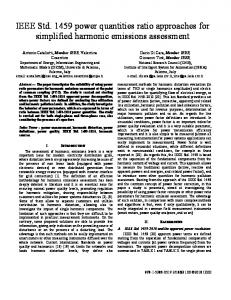
IV. IEEE STD 519 VOLTAGE HARMONIC LIMITS Table 10.2 in IEEE Std 519 establishes harmonic limits on voltage as 5% for total harmonic distortion and 3% of the fundamental voltage for any single harmonic (see Figure 1). The justification for these limits is not fully explained but a reference in Section 6.6 states that: “Computers and allied equipment, such as programmable controllers, frequently require ac sources that have no more than a 5% harmonic voltage distortion factor, with the largest single harmonic being no more than 3% of the fundamental voltage. Higher levels of harmonics result in erratic, sometimes subtle, malfunctions of the equipment that can, in some cases, have serious consequences. Instruments can be affected similarly, giving erroneous data or otherwise performing unpredictably. Perhaps the most serious of these are malfunctions in medical instruments.”[1]
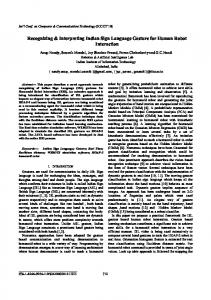
To define current distortion limits, IEEE Std 519 uses a short circuit ratio to establish a customers size and potential influence on the voltage distortion of the system. The short circuit ratio (ISC/IL) is the ratio of short circuit current (ISC) at the point of common coupling with the utility, to the customer’s maximum load or demand current (IL). Lower ratios or higher impedance systems have lower current distortion limits to keep voltage distortion at reasonable levels.
The reference to medical equipment sensitivity provides some indication as to why the limits are even more severe (less than 3% VTHD) for special applications such as hospitals and airports (see note 1 in Figure 1). In contrast, the limits are relaxed (VTHD < 10%) for dedicated systems. A dedicated system is defined as one that is exclusively dedicated to converter loads assuming the equipment manufacturer will allow for operation at these higher distortion levels.
For power systems with voltage levels between 120 V and 69,000 V, the limits can be found in Table 10.3 of the standard (see Figure 2). The table defines Total Demand Distortion (current) limits as well as individual harmonic current limits. The limits are most severe for short circuit ratios of less than 20 because this lower ratio indicates a high impedance power system or a large customer or both. Voltage distortion is more likely to develop from current harmonics consumed at a PCC where the short circuit ratio is low, thereby justifying the more severe limits.
For applications in the petrochemical industry, the general system limits are most appropriate. This means that we must design our systems for < 5% VTHD and with no single harmonic greater than 3%. These generally will be met at the PCC provided the current harmonic limits are met.
VI. DETERMINING AN APPROPRIATE POINT OF COMMON COUPLING (PCC)
Table 10.3, p78 Current Distortion Limits for General Distribution Systems
Table 10.2, p77 Low-Voltage System Classification and Distortion Limits
Notch Depth THD (voltage) Notch Area (AN)3
Special Applications1 10%
General System 20%
3% 16 400
5% 22 800
(120 V Through 69,000 V)
Dedicated System2 50% 10%
ISC/IL