Indian Journal of Radio & Space Physics Vol. 37, December 2008, pp. 408-413
Intersystem interference on horizontally polarized radio signals in tropical climate J S Ojo*,1,2, #, S K Sarkar1 & A T Adediji2 1
Radio and Atmospheric Sciences Division, National Physical Laboratory, New Delhi 110 012 2
Department of Physics, Federal University of Technology, Akure, Ondo State, Nigeria #
E-mail:
[email protected]
Received 4 December 2007; revised 12 May 2008; re-revised and accepted 8 July 2008 The nature and characteristics of tropical rainfall have called for the need to investigate horizontally polarized radio signals from Earth-to-Satellite link and to estimate intersystem interference due to hydrometeor in the tropical climate. Two rain cells, Awaka and Capsoni models, are used and results obtained from these models are compared. A difference of 5 dB has been observed between effective transmission loss (Le) and transmission loss (L) for Awaka model, whereas it is about 8 dB for Capsoni model at 0.01% of time unavailability (outage time). This suggests higher interference level in Awaka model for terrestrial and satellite communication operating at frequency above 10 GHz. The statistics of effective transmission loss over frequencies variation, station separation and terrestrial antenna gains have also been considered. Keywords: Intersystem interference, Horizontal polarization, Tropical climate, Effective transmission loss. PACS No.: 84.40.Ua; 95.85.Bh
1 Introduction The role of satellite communication continues to increase in the field of atmospheric sciences as well as some vital areas of life, viz. telemedicine, defence, internet, banking, fixed and mobile telephony among others. The trends to make use of frequencies above 10 GHz by terrestrial and earth satellite radio links are well established1, 2. However, at those frequencies, the most serious problems in system design emanated from attenuation, depolarization and scattering interference by precipitation particles along the radio path1. Interference hampers coverage and capacity, and limits the effectiveness of both new and existing systems. Assessing the extent of such interference on statistical terms is extremely important for the correct design of communication systems operating at microwave and millimeter wave frequency. In the tropical region, the quality of signals received is often affected by high intensive rainstorms that are characterized by large size raindrops on the path of communication satellite2. Although the work has been already carried out on the evaluation of bistatic interference on communication paths at temperate region, which include the work of Crane3, Capsoni et al.4, Awaka5, Olsen et al.6, Holts et al.7, Capsoni and D’Amico8, Sitorus and Glover9, etc. However, the results obtained in such studies cannot be applied directly on tropical paths. This is due to the nature and characteristics of tropical rainfall which are often convective, and characterized by large
raindrop sizes with high intensity and often accompanied by severe lightning and thunderstorm. In addition, most of these studies are based on estimation of transmission loss arising from hydrometeor scattering on vertically polarized microwave signals into the receiver of earth-space communications systems operating at the same frequency. The horizontal polarization is usually not investigated because coupling (transmission loss) between the transmitting and receiving systems is much less than in vertical polarization10. However, the nature and characteristics of tropical rainfall, which are quite distinct from the temperate rainfall, call for the investigation of the horizontal polarization of transmitted signals. The level of interference in a communication channel depends on several factors such as length and geometry of the interfering path; electrical parameters of transmitting and receiving systems; and meteorological variables associated with propagation medium. The present paper is based on evaluating the intersystem interference in terms of effective transmission loss (Le) on the transmission of horizontally polarized signals in tropical climate by using and comparing the results of two models4,5. Capsoni and D’Amico8 models reveal that transmission loss statistics alone, is not sufficient to characterize the interference problem and hence effective transmission loss is used in this work. The effective transmission loss is due to the additional rain
OJO et al.: INTERSYSTEM INTERFERENCE ON POLARIZED RADIO SIGNALS
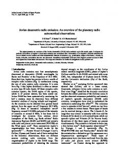
attenuation (Aw) on the path of satellite signal, which further reduces the signal-to-noise ratio at the satellite terminal (Fig.1). The study is also based on thunderstorm rainfall type, which is peculiar to the tropical region. 2 Theoretical concepts The transmission loss is estimated in terms of simplified bistatic radar equation (SBRE) using the expression L = Pt – Pr = KT + Ag – M + (S – Z + A)
…(1)
All the terms in equation (1) are in decibel (dB) units. Pt and Pr are, respectively the mean power (in watts) transmitted and received along the axis of the main antenna beams; Ag, extra attenuation due to gaseous absorption; Z, reflectivity factor; M, polarization decoupling factor; S, allowance for Rayleigh scattering at frequencies greater than 10 GHz; KT, contains the link geometry with the system parameters2; and A, slant path rain attenuation from the transmitter to the common volume and from the common volume to the satellite receiver and can be estimated from power law relationship between rain rate and attenuation11 which is expressed as A H = kH R α H
…(2)
The subscript H refers to horizontal polarization and the constant parameters kH and αH for calculating attenuation A are shown in Table 1 for the frequencies investigated in the present study. This study assumes that both M and S of equation (1) are equal to 1. This assumptions means that reflectivity factor Z is isotropic. In evaluating total or scattering cross-
409
section per unit volume of the precipitating particles, it is important to use appropriate drop size distribution (DSD) irrespective of the shape factor adopted over the frequency spectrum. In this study, the lognormal distribution is employed while Rayleigh scattering correction takes care of shape factor at frequencies higher than 10 GHz12. The detailed description for estimating L, is not included here, but can be found from the Refs 2-4. Effective transmission loss is usually evaluated in terms of a joint transmission loss, L and additional rain attenuation Aw as Le = L – Aw = Pt – (Pr + Aw) (dB)
…(3)
The result of the point rain rate measured during the joint African radiometric measurement campaign in Ile- Ife, Nigeria (4.34°E, 7.33°N) is used in this study13. The details of assumed parameters for the study are summarized in Table 2, which can be found in the work of Ajewole14 and Ajewole and Ojo2. Also, reflectivity-rain rate relationships proposed by Ajayi and Owolabi15 were used with reflectivity factor Z-R (Z = a Rb). For tropical thunderstorm rainfall, Z = 461R1.31, where a = 461 and b = 1.31 (Table 2). The study covers the frequency range 4-35 GHz while effective transmission loss and transmission loss are evaluated for probability of occurrence ranging from 0.001 to 1%. The terrestrial station path lengths to common volume distance, ranging 50-250 km and additional parameters used are also summarized in Table 2. The earth satellite system receiver is characterized with elevation angle of ~55° (This is the look angle of most satellite receiver systems over Atlantic ocean region in Nigeria), beam width ~0.18° and a gain of ~59 dB. Aside from the elevation angles, the system parameters stated in Table 2 are similar to those utilized along some propagation geometries having the same characteristics with tropical region in Cost Table 1 — Regression coefficients k and α of the power law expression for horizontally polarized states Frequency (GHz)
Fig. 1 — Rain scattering geometry between terrestrial station and Earth satellite station
4.0 6.0 8.0 10.0 12.0 16.0 20.0 35.0
kH
αH −4
6.51×10 1.85×10⁻³ 4.72×10⁻³ 1.10×10⁻² 2.20×10⁻² 4.10×10⁻² 8.20×10⁻² 2.76×10⁻¹
1.072 1.214 1.273 1.252 1.204 1.128 1.083 0.970
410
INDIAN J RADIO & SPACE PHYS, DECEMBER 2008
Table 2 — Characteristics of the station, terrestrial satellite and earth satellite Station
Ile-Ife, Nigeria
Location Frequency range Altitude Rain climatic zone hfr Transmitting antenna Elevation angle Gain Beam width Polarization Receiving antenna Elevation angle Gain Beam width Polarization Z-R relation
4.34°E, 7.33°N 4-36 GHz 274 m N and P 4.54 – 4.79 km 1° 40.5 dB 1.60, Gaussian radiation pattern Horizontal 550 59 dB 0.18°,Gaussian radiation pattern Horizontal 461 R1.31
Project 21016. The vertical structure of precipitation is assumed constant up to 0°C isotherm height, below which is the rain region where attenuation and scattering of the wanted and interfering signals occur. Beyond 0oC, is the ice region where Z decreases at the rate of 6.5 dB/km. In Nigeria, during raining conditions, the mean freezing height (hFR) is nearly constant and hence equal to h0. Its value lies between 4.54 and 4.79 km from the coast to the arid region of the country17. These parameters, however, show a strong seasonal variation. To assess the height variation impact on the predictions; simulations have been carried out using hFR as proposed by Cost 21016. The effect of using hFR, instead of its median height h0, brings a better estimation of interference statistics since height of the common volume is well above the median h0. The effect of the atmosphere has been taken into account by complex propagation constant in the bistatic radar equation8. The intersystem interference prediction has been carried out using extra attenuation due to rain (with respect to the free space) that the signal experiences along the path towards and from the common volume. The two main contributions to attenuation come from precipitation and to a lesser extent, the atmospheric gases. In the earlier work of Ajewole et al.12, intersystem interference has been estimated over different rainfall types (thunderstorm, widespread and shower) and their effects have been considered on vertically polarized radio signal. In this work, gaseous absorption is calculated using the relation provided by the International Telecommunication Union (ITU)18 with an average water vapour density of ~ 20 g/m3, as
recommended in Cost 21016. Raindrop shapes are assumed to be oblate spheroids at ~ 20°C using lognormal distribution, which has been proved to fit better in describing the rain drop size distribution in the tropical region10,11. The value was used to evaluate the refractive index of water using the method described by Ray19. The horizontal structure of rain rates are assumed to be exponentially distributed with peak intensity inside the rain cells and are expressed as
R(r)=R M e
−r ro
…(4)
where, r, is radial distance from the rain cell center; RM, maximum rainfall rate; and ro, distance of the point from the centre of rain cell for which rain rate decreases by a factor e-1 with respect to the rain rate value inside the cell, and this corresponds to minimum rain rate in the cells. For Capsoni4 and Awaka5 rain cell models ro is expressed respectively as R −10 R −0.26 …(5) ro ( R M ) = 1.7 M + M km 6 6 ro ( R M ) =
10 − 1.5log10 R M km R ln M 0.4
…(6)
Equations (5) and (6) differentiate the two models from each other. The probability of occurrence of a rain cell is defined in terms of the total number of rain cells N* (RM) for a given area per unit rain rate R(r). A general retrieval algorithm for N as proposed by Awaka5 can be expressed as N* ( RM ) =
−1
d3P ( R )
2πRmro2 ( RM ) d ( lnR )3 R=RM
…(7)
For the Capsoni model4, the denominator of the first term on the right is two times higher. By using third order differentiation, this equation is solved in terms of a power law relationship for the cumulative distribution of measured rain rate P(R) at the location of interest as k
R′ P ( R ) =Po ln 0