Interworking between WLAN and WMAN: an Ethernet-Based Integrated Device Simone Frattasi Department of Communication Technology, Aalborg University Aalborg, Denmark
[email protected]
Ernestina Cianca Department of Communication Technology, Aalborg University Aalborg, Denmark
[email protected]
Abstract This paper addresses the issue of the efficient interworking between a Wireless Local Area Network (WLAN) and a Wireless Metropolitan Area Network (WMAN), in particular High Performance Local Area Network (HiperLAN) and High Performance Metropolitan Area Network (HiperMAN) standards. The dual mode interworking must guarantee Quality of Service (QoS) through the whole system. One of the main conditions to make the solution feasible and commercially interesting is to require few/none changes to the current standards. To accomplish this goal and keep low the implementation complexity, an Ethernet bridging mechanism is proposed. In particular, this paper gives a detailed description of the User Plane and Control Plane of an integrated device that implements an Ethernet-based interworking. The advantages with respect to Internet Protocol (IP) bridging and Data Link Control (DLC) bridging are carried out.
Ramjee Prasad Department of Communication Technology, Aalborg University Aalborg, Denmark
[email protected]
2. Payload Header Suppression (PHS). In PHS mode, a repetitive part of the payload header of the CS SDU is suppressed by the sending entity and restored by the receiving entity. 3. Delivery of the resulting CS Protocol Data Unit (PDU) to the MAC Service Access Point (SAP) in accordance with the QoS associated with a particular connection’s SF characteristics.
Keywords BFWA, HiperLAN/2, HiperMAN, IEEE 802.11e, IEEE 802.16, Interworking, Mapping Differentiated Services to Link Layer QoS, QoS, WLAN, WMAN.
1. Introduction Future Broadband Fixed Wireless Access (BFWA) systems envisage two types of cellular structure: macrocell type (cell radius < 10km, Base Station (BS) height between 15m to 40m) and microcell type (cell radius < 2km, BS height typically lower than rooftops). A microcell radio architecture is needed to provide indoor coverage. Alternative solutions are currently investigated in the framework of the IST STRIKE project (SpecTRally Efficient FIxed Wireless NetworK basEd on Dual Standards, project Proposal no.: IST-2001-38354) [1], such as the possibility of extending the indoor coverage of HiperMAN by defining an efficient interworking mechanism with a WLAN (e.g. HiperLAN/2). In this paper, we first present three possible solutions for the interworking. We then focus on the Ethernet bridging, which has been shown to be the best trade-off between implementation complexity and QoS guarantees [2]. The detailed description of the User Plane and Control Plane of an integrated device that implements an Ethernet-based interworking is given.
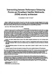
Figure 1 — HiperMAN protocol layering HiperMAN defines two general service specific CSs for mapping services to and from HiperMAN MAC connections. The ATM convergence sublayer is defined for ATM services, and the packet convergence sublayer is defined for mapping packet services such as Ethernet, IP version 4 (IPv4), IP version 6 (IPv6), and Virtual Local Area Network (VLAN). Classification of plain IEEE 802.3 Ethernet and 802.1Q VLAN are also supported. In the case that IP is carried encapsulated in Ethernet, the fields from the IP header can be included in the filter.
1.1 HiperMAN Convergence Layer (CL) The HiperMAN protocol [3-4] (Figure 1) defines a PHYsical layer (PHY), a Medium Access Control layer (MAC) and within the MAC, a Service Specific Convergence Sublayer (CS) for transport of Ethernet, IP or Asynchronous Transfer Mode (ATM). The CS has three main functions: 1. Classification. It is the process of associating external network Service Data Units (SDUs) to the proper MAC Service Flow (SF) and Connection IDentifier (CID) (Figure 2).
Figure 2 — Classification and CID mapping (SS to BS) A Classifier contains matching criteria checking one or more of the items below : • IP source and destination addresses;
• • • • • • • •
IP protocol field; IP ToS/DSCP/Traffic Class field; TCP/UDP/SCTP port numbers; Logical Link Control (LLC) destination and source MAC address; LLC Ethertype/SAP; IEEE 802.1D User priority; IEEE 802.1Q VLAN-ID; Vendor specific parameters.
A service flow is an unidirectional flow of packets that is provided with a particular QoS. The primary purpose of the QoS features is to define transmission ordering and scheduling on the air interface. They may contain detailed information about bandwidth needs, indicated by parameters like “maximum sustained traffic rate”, “maximum traffic burst” or “minimum reserved traffic rate”. Furthermore, delay requirements of an SF can be specified by parameters such as “tolerated jitter” or “maximum latency”.
1. Service Specific Convergence Sublayer (SSCS). Its function is the mapping and routing of data packets. The convergence layer maps different traffic types into different classes and consequently onto different radio bearers. For example, if we assume that Ethernet quality of service is supported via IEEE 802.1p, then the priority indicated in the additional tag field stipulates the type of traffic to be carried in the packet. 2. Common Part Convergence Sublayer (CPCS). It converts higher-layer packets of fixed or variable length into a fixed length SDU that is used within the DLC. The padding, segmentation and reassemble function of the fixed-length DLC service data units is a key feature that makes it possible to standardize and implement the DLC and PHY layers independently of the core network. Figure 5 depicts the mapping of higher-layer data units down to PHY bursts.
1.2 HiperLAN/2 CL The HiperLAN/2 standard [5-9] specifies a radio-access network that can be used with a variety of core networks. This is made possible b y a flexible architecture that defines core network independent PHY and DLC layers and a set of CL’s that facilitates access to various core networks (Figure 3).
Figure 5 — Mapping of HL packets onto the layers of HiperLAN/2 Several SSCS have been or currently are being defined for interworking with IP transporting networks (e.g. Ethernet and Point-to-Point Protocol (PPP)), ATM based network, 3rd generation core network, and networks using IEEE 1394 protocols and applications.
Figure 3 — Architecture of the HiperLAN/2 protocols There are two types of CL: 1. Cell-based convergence layer. It handles higher layers with fixed-length packets - for instance, ATM-based core networks. 2. Packet-based convergence layer (Figure 4). It handles higher layers with variable length packets - for instance, Ethernet.
The Ethernet SSCS makes the HiperLAN/2 network look like wireless segments of a switched Ethernet. Ethernet SSCS SDUs coming from the higher layer are mapped onto different DLC user connections, depending on the Ethernet destination address and priority. It supports two quality of service types: 1. Best Effort (BE). This is the default QoS type that shall be supported. All traffic is treated equally and no quality of service guarantees can be provided. 2. IEEE 802.1p priority based QoS scheme. IEEE 802.1p provides priority mechanisms to enable quality of service in LAN. Eight (numbered 0-7) different priority levels are defined. The user priorities are mapped one-to-one or many to- one to queues, depending on the number of queues supported. In HiperLAN/2 each queue corresponds to one DLC User Connection (DUC). The user priority information is carried in each IEEE 802.3 frame using a tag header inserted following the source and destination address.
2. Interworking methods
Figure 4 — General structure of the packet-based convergence layer The CL consists of the following two sublayers:
Figure 5 summarizes three alternative approaches to the interworking problem. The two networks can be connected at IP level (IP bridging). In this case, QoS parameters will not be exchanged between the two networks and services like videoon- demand or teleconferencing would be very hard to be provided with an acceptable quality. The negotiation of relevant QoS parameters could only be based on standard IP header fields, like the Type Of Service (ToS) field in case of IPv4 or the ‘Traffic Class’ and ‘Flow Label’ fields in case of IPv6. The HiperLAN and HiperMAN QoS settings should be mapped onto each other indirectly with the aid of the IP header fields.
Table 1— Traffic type to user priority mapping
4. Ethernet-based integrated device Figure 5 — Possible methods for end-to-end QoS provisioning The second method to make the two standards interoperating is at DLC level (DLC bridging). Due to different packet formats accepted by the DLC layers, no direct data exchanging is possible; the support of the convergence layers is needed. So far, it is also not feasible an exchange/conversion/adaptation of QoS parameters between the two systems as stated in [1], as in HiperLAN/2 at connection setup there is an implicit definition of the QoS supported by one connection, while in HiperMAN, through the definition and association of a service flow to a connection, this process is explicit. A DLC bridging might be very complex to implement and difficult to adapt to eventual standards evolution.
4.1 User Plane Figure 7 describes all the actions to transfer data in the uplink direction (MT-BRIDGE-BS).
3. Ethernet bridging Figure 6 depicts the protocol stack of the bridge device that implements an Ethernet-based interworking.
Figure 6 — HiperLAN/2-HiperMAN: bridge layer architecture The main features of this technique are the following: •
•
It uses the CLs. By using them, the interworking mechanism is made independent from the layers below (MAC and PHY) since the differences between the two standardized MAC layers are absorbed. Moreover, the introduction of the Ethernet SSCS allows the use of the Ethernet QoS support by inserting in the Ethernet frame a 3 bits user priority or using the user priority field included in the tag header of the 802.1ac frame [10]. This tag header identifies one of the eight priority levels, as defined in the IEEE 802.1p extension of the standard IEEE 802.1D [11], and described in Table 1. It uses the IEEE 802.1D bridge (including IEEE 802.1p). This kind of bridge supports expedited traffic capabilities by using multiple queues for every exit port. Each queue is identified by a specific priority. The bridge distributes packets in the HiperLAN/2 network and from HiperLAN/2 to HiperMAN network, and vice-versa. This allows the communication either between HiperLAN/2 and HiperMAN or with other Ethernet-based devices.
Figure 7 — Ethernet bridging: User Plane Ethernet packets coming from the Higher Layers (HLs), contain the user priority coded with 3 bits in the tag header field. The functions implemented by the Ethernet SSCS user plane include the traffic class mapping according to 802.1p. This function provides the mapping of different traffic classes to different priority queues, depending on how many priority queues are supported. IEEE 802.1p defines 8 priorities and describes which type of traffic is expected to be carried in this priority. The mapping between user priority, traffic type, traffic class and DLC Connection Identifier (DLCC_ID) is described in Table 1 and Table 2. Different traffic classes are mapped to different DLCCs. After connection set-up the Radio Link Control (RLC) indicates which DLCC_IDs have been assigned to DLCCs in a list and traffic classes are mapped to DLCC_IDs depending on the numerical order of the value of the DLCC_IDs, as shown in Table 2. When packets arrive into the HiperLAN/2 side of the bridge, after the procedures developed by the Segmentation And Reassembly (SAR) and the Common Part Convergence Sublayer (CPCS), the Ethernet SSCS interacts with the MAC relay entity of the IEEE 802.1D bridge to send packets on the HiperMAN side of the bridge. It is worth noting that 802.1D will continue to use the user priority value already contained in every packet. The classification between every incoming packet and a specific CID, which implicitly identifies a specific SF, is made on the HiperMAN side of the bridge. This classification procedure shall use the user priority value contained in the tag information field of the frame.
4.2 Control Plane Since we have introduced a traffic classification based on 8 priority values, it is natural to use service flows that are pre-
provisioned and to shape the QoS needs of each type of traffic that is supported in the best way. At connection setup, the BS assigns a specific Service Flow IDentifier (SFID) to each preprovisioned SF. Before classifying a packet to its own HiperMAN connection, the MAC_CREATE_CONNECTION procedure should be developed; only after this three-way handshake has been completed it is possible to associate each packet to a connection, implicitly using the CID. To speed up this process and to activate the HiperMAN connections only when needed, the HiperLAN/2 resource allocation mechanisms [12] are exploited. In this case, these pre-defined service flows can be switched from pre-provisioned to active, using the Resource Request (RR) message either in the basic allocation mechanism or in the Fixed Capacity Agreement (FCA) mode. When the first RR is received, the HiperLAN/2 CL sends a primitive to the HiperMAN CL, which enforces the MAC_CHANGE_CONNECTION procedure, including in the consequent MAC management message the appropriate QoS Parameter Set Type. If a Mobile Terminal (MT) is absent for any RLC reason, (e.g. MT Absence or MT Dynamic Frequency Selection (DFS) Measurement), the same procedure is invoked to de-admit or even de-activate a specific SF. This methodology can be used to modify the characteristics of a service flow time by time. This operational mode is useful since, in the periods when the bridge does not claim resources for a particular connection, the HiperMAN BS can reuse the overall bandwidth. Table 2 — Traffic class to DLCC-ID mapping
network, where the QoS policy is based on the IEEE 802.1p user priority values. In case of IP traffic, the IP packet is inserted in an Ethernet frame and the Differentiated Services CodePoint (DSCP) field is mapped onto the IEEE 802.1p field. Then the frame is forwarded into the access network according to the user priority value. An example of the recommended mapping between Differentiated Service (DiffServ) classes and Ethernet user priorities is presented in Table 3 [13]. Moreover, any Layer 3 protocol running over Ethernet can be marked with an 802.1p value: this is an advantage of 802.1p over DiffServ, since DiffServ is only useful in IP-based networks. Table 3 — DiffServ class to Ethernet user priority mapping
6. Advantages The advantages of this solution are: • High applicability to the standards. Even if the focus is on HiperLAN/2 and HiperMAN, it is easily applicable to every WLAN (e.g. IEEE 802.11e [14]) and WMAN (e.g. IEEE 802.16) system; for example, in Figure 8 is depicted the Ethernet bridge architecture applied to the interworking between IEEE 802.11e and HiperMAN. • Low complexity of the implementation. Implementation of priority tagging in Ethernet CL. • Slight complexity of the changes in the involved standards. Pre-provision of 8 service classes. • Flexibility towards evolution of the standards. Changing the QoS parameters does not change the implementation (it concerns the updating operation at the BS of the QoSParamSet of the same pre-provisioned service flows. In this way, the service flows are always referred with the same ‘Service Class Names’ - users are transparent to this updating process). • Possible extendibility to multiport.
5. An extended access network The described interworking scenario can be seen as the combination of two independent networks: an access network, which makes the HiperLAN/2 user transparent to the access technology, and a core network. In such a scenario, we divide the problem into two parts, distinguishing among access QoS mechanism and core QoS mechanisms. In this way, our interworking problem turns out to be an access problem. For an HiperLAN/2 user, the wireless bridge is “fictitious”, it is like to connect the computer directly to a core network. When the described Ethernet bridging solution is considered, the user is connected directly to an extended Ethernet wireless access
Figure 8 — IEEE 802.11e-HiperMAN: bridge layer architecture Another strong point for the Ethernet approach is the simplicity of integration into existing network infrastructures. 802.3 networks use the IEEE MAC address to identify terminals. This address does not contain any information on how to reach a terminal, in contrast to IP addresses. The packets are either broadcast and grabbed by the target terminal, or they are switched where the switches contain
routes for every single MAC address for which they have recently received and forwarded packets. Thus, as long as a terminal stays within an IP subnet, no effort for mobility support beyond the HiperLAN/2 specific procedures is necessary. Only in the rare case that the IP subnet is changed, IP mobility support is required [15].
7. Conclusions The advantages of implementing an Ethernet bridging for the interworking between HiperLAN/2 and HiperMAN standard on an integrated device have been discussed. As it is shown in Table 4, which is an output of the STRIKE project [2], applicability to current standards and lower implementation complexity make the Ethernet approach the most interesting mechanism for the bridging between HiperLAN/2 and HiperMAN. Implementing the protocol stack of the two standards in a unique device provides versatility and a high level of interoperability. The capability to handle congestion conditions in one of the network is another important requirement for the selection of the interworking mechanism. The congestion management proposed in [2] can be easily applied to the presented device.
8. Acknowledgements The authors acknowledge the financial support of the European Commission under the IST-2001-38354 STRIKE project, and also thank all the partners involved in WP3 of the IST-STRIKE for the fruitful cooperation.
9. References [1] E. Diaz, M. Engels, E. Cianca, M. Chenu-Tournier, A. Hutter, K. Wachsmann, C. Politis, I. Forkel, P. Rosson, and D. Noguet, “STRIKE: spectrally efficient fixed wireless network based on dual standards”, accepted for publication in Proceedings of SympoTIC 2003 Conference. [2] Christian Hoymann, Simone Frattasi, Peter Coenen, “D3.1.1 HIPERMAN/HIPERLAN/2 interworking methods”, STRIKE deliverable, June 2003 (http://ist-strike.org). [3] C. Eklund, R. Marks, K. Starwood, and S. Wang, “IEEE
Standard 802.16: A Technical Overview of the WirelessMAN Air Interface for Broadband Wireless Access”, IEEE Communication Magazine, Volume: 40, Issue: 6, June 2002, Page(s): 98 -107. [4] IEEE Std 802.16-2001, IEEE Standard for Local and Metropolitan area network, “Part 16: Air Interface for Fixed Broadband Wireless Access Systems”. [5] G. Malmgrem, J. Khun-Jush, P. Schramm, and J. Torsner, “HiperLAN type 2 for broadband wireless communication”, Ericsson Review no 2, 2000.
[6] ETSI TS 101 493-2 (V1.1), "Broadband Radio Access Networks (BRAN); HIPERLAN Type 2; Packet based Convergence Layer; Part 2: Ethernet Service Specific Convergence Sublayer (SSCS)". [7] ETSI TS 101 493-1 (V1.1.1), "Broadband Radio Access Networks (BRAN); HIPERLAN Type 2; Packet based Convergence Layer; Part 1: Common Part". [8] ETSI TS 101 761-1, "Broadband Radio Access Networks (BRAN); HIPERLAN Type 2; Data Link Control (DLC) Layer; Part 1: Basic Data Transport Functions". [9] ETSI TS 101 761-2, "Broadband Radio Access Networks (BRAN); HIPERLAN Type 2; Data Link Control (DLC) layer; Part 2: Radio Link Control (RLC) sublayer". [10] IEEE 802.3ac-1998, "Information technology Telecommunications and information exchange between systems - Local and metropolitan area networks – Specific requirements Part 3: Carrier sense multiple access with collision detection (CSMA/CD) frame extensions for Virtual Bridged Local Area Networks (VLAN) tagging on 802.3 networks". [11] ISO/IEC 15802-3 (1998) [ANSI/IEEE Std 802.1D, 1998 Edition], "Information technology - Telecommunications and information exchange between systems - Local and metropolitan area networks - Common specifications - Part 3: Media Access Control (MAC) Bridges". [12] E. Mingozzi, "QoS Support by the HiperLAN/2 MAC Protocol: A Performance Evaluation", Cluster Computing, Vol. 5, No. 2, pp. 145-155, April 2002. [13] L. Yao, D. MCDysan, and D. Rawlins, “Differentiated services over specific link layers”, SCI 2001/ISAS 2001, Volume XII, Part II. [14] IEEE Std 802.11e/D4.0, “November 2002 Draft Supplement to IEEE standard for Telecommunications and Information exchange between systems – LAN/MAN specific requirements. Part 11: wireless LAN Medium Access Control (MAC) and Physical Layer (PHY)specifications: Medium Access Control (MAC) Enhancements for Quality of Service (QoS)”. [15] M. Radimirsch, J. Khun-Jush, "Application of HIPERLAN Type 2 Systems in Private Environments", International Conference on Telecommunications, Acapulco, Mexico, May 2000.
Table 4 — Comparison of the interworking mechanisms