Journal of Naval Architecture and Marine Engineering December, 2015 http://dx.doi.org http://dx.doi.org/10.3329/jname.v12i2.22351 http://www.banglajol.info
INTRODUCING A PARTICULAR MATHEMATICALMODEL FOR PREDICTING THE RESISTANCE AND PERFORMANCE OF PRISMATIC PLANING HULLS IN CALM WATER BY MEANS OF TOTAL PRESSURE DISTRIBUTION P. Ghadimi1*, S. Tavakoli1, M. A. Feizi Chekab1, A. Dashtimanesh2 1 2
Department of Maritime Engineering, Amirkabir University of Technology, Tehran, Iran, *Email:
[email protected] Faculty of Engineering, Persian Gulf University, Bushehr, Iran
Abstract: Mathematical modeling of planing hulls and determination of their characteristics are the most important subjects in hydrodynamic study of planing vessels. In this paper, a new mathematical model has been developed based on pressure distribution. This model has been provided for two different situations: (1) for a situation in which all forces pass through the center of gravity and (2) for a situation in which forces don not necessarily pass through the center of gravity. Two algorithms have been designed for the governing equations. Computational results have been presented in the form of trim angle, total pressure, hydrodynamic and hydrostatic lift coefficients, spray apex and total resistance which includes frictional, spray and induced resistances. Accuracy of the model has been verified by comparing the numerical findings against the results of Savitsky's method and available experimental data. Good accuracy is displayed. Furthermore, effects of deadrise angle on trim angle of the craft, position of spray apex and resistance have been investigated. Keywords: Planing hulls, mathematical modeling, resistance and performance, hydrodynamic characteristics, spray apex
1. Introduction Determination of the resistance and effective power and prediction of the running trim angle, lift coefficient, spray apex and other characteristics of the planing crafts are very important in their design. Many researchers have studied hydrodynamics of the planing hulls and have tried to predict these parameters. Hydrodynamics of the planing hulls was first studied through experimental methods. Through these efforts, many parametric studies were performed and effects of each of the intended parameter were examined, while other parameters were kept fixed. One of the most important results of these experiments was produced by Sottorf (1934) who tried to investigate the pressure distribution. In all likelihood, it was him who analyzed the pressure distribution and the effect of some parameters on it, for the first time. Smiley (1951) also made an important contribution in this regard. Important data resulted from his work which represented three dimensional pressure distributions. Pressure distribution on the planing hulls was also investigated by Pierson and Leshnover (1948) and Kapryan and Boyd (1955). Experimental studies were not limited to the analysis of pressure distribution and also included the lift force. Experiments on lift force by Korvin-Kroukovsky et al. (1949) resulted in an empirical equation for determining the lift force of the planing surfaces. On the other hand, computing the wetted area and the center of pressure were other important issues in this regard. Other experiments conducted by KorvinKroukovsky et al. (1950) led to some new empirical equations for these important factors. Furthermore, Pierson and Leshnover (1950) tried to explore the phenomena related to the spray root. As a result of their experimental study, the bottom of a planing surface was divided into two areas of spray and pressure. Some important experimental data can also be found in the work by Lock (1933). However, prediction of performance of a planing hull was an issue which hadn’t been solved yet. As a result of Lock’s effort (Lock, 1948), it was found that there is an inception point in the planing surfaces, i.e. when these crafts reach a specific speed coefficient, planing reign begins, and trim angle varies with speed coefficients. Consequently, trim angle, wetted length, resistance, and some other hydrodynamic characteristics were unknown. In all of the mentioned studies, trim angle, wetted length, speed coefficient among other factors were assumed known, in advance. However, these assumptions could not be considered practical for a naval architect in designing a planing hull, because accurate prediction of resistance and performance is not possible without the trim angle and mean wetted length of the planing surface. In order to overcome this difficulty, a new method was developed by Savitsky (1964) which 1813-8535 (Print), 2070-8998 (Online) © 2015 ANAME Publication. All rights reserved.
Received on: February 2015
P. Ghadimi, S. Tavakoli, M. A. F. Chekab, A. Dashtimanesh/Journal of Naval Architecture and Marine Engineering, 12(2015) 73-94
was based on empirical equations. A computational procedure was presented and the trim angle of a planing hull was obtained. Subsequently, the resistance and effective power were calculated. Savitsky and Brown (1976) made some efforts to further enhance the developed method by Savitsky (1964) in order to consider the warped hull shape and trim tab effects in their computations. In the same year, Blount and Fox initiated an empirical method for power prediction of planing craft. Latorre, on the other hand, focused on the flow around a planing boat. Latorre (1982) focused on wave pattern and its resistance component in planing motion. Later, Latorre (1983) investigated the spray of planning boats and frictional resistance acting on the bottom of a planing vessel. In another research by Latorre (1993), a parameter was introduced in order to identify whether or not spray blister is broken down into droplets. Some years later, Zarnick (1978) established a new method for modeling the prismatic planing hulls in waves based on the added mass and strip theories. The origin of his work can be found in a study conducted by Von Karman (1929) who tried to find the hydrodynamic force of the water impact using virtual mass. Payne (1982) was another researcher in this field who made progress in theories related to the added mass theory in planing condition. His works started by computing the hydrodynamic load. However, it could also be used to predict the performance of the planing hulls. In addition to empirical methods and strip theory, numerical methods reached an important level in predicting the performance of the planing hulls. Zhao and Faltinsen (1993) numerically investigated the water entry of wedge shaped bodies using boundary element method (BEM) to find pressure distribution. Later, Zhao et al. (1996) using the obtained pressure distribution and by applying 2d+t theory calculated the performance of planing hulls in calm water. Finally, in the last decade, some important equations were developed by different researchers to determine spray resistance, pressure distribution, and spray apex. Van Deyzen (2008) used added mass planing theory and satisfied surge motion equation of a planing boat in order to compute the planing hull motion in calm water. Kim et al. (2013) also proposed a new method based on the added mass planing theory and pressure acting on a planing plate to compute the trim and resistance of the round bilge semi planing hulls. Recent advances in this field (2d+t theory)have led to new progress in motion prediction of planing hulls such as efforts by Ghadimi el al. (2013a) for predicting six degrees of freedom motion, research by Morabito (2015) for yaw force prediction, Tavakoli et al. (2015) and Ghadimi et al. (2015) for roll motion prediction. It should be noted by the recent advances in water entry problem, today, some other alternative methods for determining forces acting on a section exists such as FVM (Ghadimi et al., 2014) or SPH (Farsi and Ghadimi, 2014). On the other hand, Savitsky et al. (2007) offered an empirical relation for predicting the spray resistance. Later, Saymsundar and Datla (2008) proposed a modification of Savitsky’s method in order to consider the interceptors effect in performance prediction. Afterward, Bertorello and Oliviero (2007) further developed Savitsky method to predict the performance of a warped planning hullform. Savitsky (2012) also offered an empirical model in order to modify his 1964 model for modeling the warped planing boats. In the recent years, Morabito (2010) presented a comprehensive discussion on the spray and pressure of the planing vessels. On the other hand, Savitsky and Morabito (2011) derived an equation for calculation of the position of spray apex of the planing hulls. Ghadimi et al. (2014) also performed a detailed study of the spray generated by planing hulls and investigated the effects of geometrical and physical parameters on the spray. Recently, Tavakoli et al. (2013) used Morabito's (2010) method for determination of the longitudinal dynamic pressure. Subsequently, Ghadimi et al. (2013b) introduced a procedure for computing the three-dimensional hydrodynamic and hydrostatic pressure distribution on the planing hulls. In this paper, the derived equations by Morabito (2010) and the developed computational method by Ghadimi et al. (2013b) are utilized for determination of the performance of planing hulls in two different practical situations including one in which all forces pass through the center of gravity (CG) and the other in which not all forces pass through the CG. First, an iterative method is introduced for computing the running trim angle and the mean wetted length for both of these cases. Subsequently, these computed parameters are used along with empirical equations of the frictional and spray resistance to calculate the total resistance of a planing hull. On the other hand, the mentioned analytical relation of the spray apex developed by Savitsky and Moabito (2011) is included in the procedure and computed. Accuracy of the model is validated by comparing the current results against Savitsky’s method and available experimental data. Effects of deadrise angle on the running trim angle, spray apex, and resistance are investigated and variations of these characteristics are examined based on the changes in speed coefficient. The proposed model may be considered as the initial point for modeling the motion of the planing boats in waves.
Introducing a particular mathematical model for predicting the resistance and performance of prismatic planing hulls…
74
P. Ghadimi, S. Tavakoli, M. A. F. Chekab, A. Dashtimanesh/Journal of Naval Architecture and Marine Engineering, 12(2015) 73-94
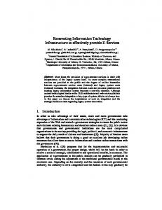
2. Pressure Distribution on Planing Hulls 2.1 Hydrodynamic pressure As a planing plate moves forward, a stagnation point is generated and a maximum pressure occurs at the stagnation point. Subsequently, dynamic pressures of the points behind the stagnation point decrease as their distance from the stagnation point increases and the pressure becomes zero at the stern of the plate, as shown in Fig. 1. Pressure distribution on a planing hull is similar to the plot shown in Fig. 1, but slightly different. In these crafts, there is a stagnation line at the bottom of the hull as discussed by Pierson and Leshnover (1950), and if the longitudinal sections are used, there is a stagnation point and a maximum value for the dynamic pressure in every section. Dynamic pressure distribution in every section can be calculated using equations presented by Morabito (2010) and the computational procedure developed by Ghadimi et al. (2014) as follows: 1
PD 1 V 2 2
CX 3 PT X K
(1)
Different parameters and variables in Equation (1) can be determined using Equations (2) through (9). 1
C 0.006 PY 3 K
PT
C
(2) (3)
1. 5 1.5
P 2.58 MAX 1 V 2 2 1.4 y X
(4)
X 0.05 1. 4
y
PY 1.02 0.05( 5)Y 1.4
00..515 YY
P PMAX YSTAG sin 2 1 PN V 2 2 PYSTAG 0 .5 Y [1.02 0.25Y 1.4 ] PN 0.51 Y
(Y 0.25) tan tan tan 1 2 tan
y
(5) (6)
(7)
(8) (9)
Here, C and K are two parameters which are constant in each longitudinal section. PY is a parameter which causes the transverse decrease of the pressure and (PMAX/q) is the maximum pressure in each longitudinal strip. α is the angle between the stagnation line and the keel, while λy is the non-dimensional distance from the transom stern. PT is the parameter which expresses the decreasing pressure in the longitudinal strips and causes the pressure at the transom to diminish. Finally, P YSTAG / PN represent pressure distribution on the stagnation line. All these parameters are explained in detail by Morabito (2014). Regarding the range of applicability of these equations, the following range has been previously used by Morabito (2010) in his studies which may be considered as a suitable range of applicability.
Introducing a particular mathematical model for predicting the resistance and performance of prismatic planing hulls…
75
P. Ghadimi, S. Tavakoli, M. A. F. Chekab, A. Dashtimanesh/Journal of Naval Architecture and Marine Engineering, 12(2015) 73-94
CV 2
45 2 30
Pressure Distributian
Spray
Fig. 1: Longitudinal dynamic pressure distribution on planing plate (Sottorf, 1934) However, there is no limitation for the mean wetted length. In Equations (1) through (9), X is the nondimensional distance from the stagnation point at each longitudinal section and Y is the non-dimensional distance from the keel which is illustrated in Fig. 2 and is obtained using Equation (10). Determination of X and Y require the descretization of the bottom of the hull which requires a finer mesh resolution for better accuracy. Errors many emanate from this step if size of the involved mesh is not fine enough. Part of the inevitable errors involved in the proposed mathematical model may also be attributed to the errors of numerical integration for determining the lift coefficient that will be explained in the next section.
X x/B
(10) Y y/B By using the longitudinal sections and Equations (1) through (9), the dynamic pressure acting on the bottom of a planing hull with specified trim and deadrise angles as well as mean wetted length can be predicted.
2.2 Hydrostatic pressure The hydrostatic force acting on the bottom of a planing surface is not equal to the buoyancy force, since the hydrostatic pressure is affected by the transom stern and the chine as dynamics pressure is affected, too. Hydrostatic pressure can be computed using a relation proposed by Morabito (2010) as in
PB 1 V 2 2
2 PT PY sin CV2
1 1 X Y ( ) tan tan w
(11)
where αW is the angle between calm water and the keel that can be written in the form of tan W tan 1 ( ) tan
(12)
Keel 𝑦
Transom
𝑥
Stagnation line
Chine Fig. 2: Distances form stagnation line and center line for a point in the bottom of a planing hull Numerical treatment of fluid flow for maritime crafts are much more complex than other types of vehicle because of special environmental treatments associated with its operation for example sailing at a free surface. Academic and research organizations have devoted long potential on numerical simulations in the maritime field accompanying traditional model testing. Introducing a particular mathematical model for predicting the resistance and performance of prismatic planing hulls… 76
P. Ghadimi, S. Tavakoli, M. A. F. Chekab, A. Dashtimanesh/Journal of Naval Architecture and Marine Engineering, 12(2015) 73-94
Finally, total pressure acting on the bottom of a planing hull can be computed by summation of the hydrostatic and hydrodynamic pressures.
PTOTAL PD PB 1 1 1 V 2 V 2 V 2 2 2 2
(13)
3. Lift and Center of Pressure Lift force of a planing hull can be calculated by integration of the dynamic and hydrostatic pressures. Lift coefficient includes two terms; hydrodynamic and hydrostatic lifts. Lift coefficient is given in Equation (14), where the first term represents the hydrodynamic lift coefficient and the second represents the hydrostatic lift coefficient (Morabito, 2010). 0.5 y
CL
1
0.5 0
2
0.5 y
PD
V
dXdY 2
1
0.5 0
2
PB
V
dXdY 2
(14) Non-dimensional position of the center of pressure from the stern can also be obtained by using equation
l P 0.5 y ( PD PB )( y X ) dXdY 1 B 0.5 0 2 V 2 which is introduced by Morabito (2010).
(15)
4. Resistance of Planing Hulls Resistance of a planing hull can be obtained by applying the Savitsky’s method (1964) which is written in the form of
R tan
Df
cos here, Δ is the weight of the boat and Df is the frictional drag and is evaluated from Equation (16) to be Df
V 2 C F b 2 2 cos
(16)
(17)
where
0.0075 0.0004 (log Rn 2) b Rn V
CF
(18) (19)
Savitsky et al. (2007) derived an equation in order to compute the viscous force of the spray on a planing hull as in
1 B 2 cos (20) V 2 2 2 sin 2 cos Where Θ is the angle between the forward edge of the whisker spray and the keel line in a plane that passes through the keel and is perpendicular to the hull center plane. Θ is written as RS
cos
2
Introducing a particular mathematical model for predicting the resistance and performance of prismatic planing hulls…
(21) (22)
77
P. Ghadimi, S. Tavakoli, M. A. F. Chekab, A. Dashtimanesh/Journal of Naval Architecture and Marine Engineering, 12(2015) 73-94
In the proposed mathematical model, Equations (16) and (20) are used for calculation of the total resistance. On the other hand, the effective power of the planing hull can be written as:
PE RT V where,
(23)
(24) RT R f RS Ri In Equation (24), Rf is the frictional resistance which is Df ⁄cosτ and Ri is the induced resistance being Δ tanτ.
5. Spray Apex Spray apex may be also considered as another important parameter in planing hull motion and has been highlighted by some researchers. For instance, Latorre and Tamiya (1975) developed an experimental method to measure spray around the planing boats. Latorre (1983) also developed a model for studying the spray apex. Recently, Savitsky and Morabito (2011) developed a new method for computing the spray apex position based on the swept wing theory. In the current paper, their method is utilized in order to determine the spray apex along with resistance, trim angle, and wetted length. In the developed by Savitsky and Morabito (2011), two components are considered for the velocity vector: 1) velocity component along the stagnation line shown as (Vs) and 2) velocity component normal to the stagnation line depicted as (Vn). In order to compute the spray apex, vertical velocity of the spray (VV) should be calculated first and subsequently the spray apex is determined using the projectile principle. Vertical velocity of the spray is given by
VV Vn VS V V sin V cos sin sin E
(25)
In this equation, βE is the angle between the stagnation line and the horizon in transverse plane and can be obtained using Equation (26), while VSV is the vertical component of the velocity along the stagnation line in the transverse plane. The height of the spray apex is found using Equation (27) and the longitudinal and lateral positions of the spray apex can be determined using Equations (28) through (30). 2 (26) E tan 1 1 tan V2 (27) Z' V 2g
LH Vs
2z g
X ' L H cos Y ' L H sin
(28) (29) (30)
Here, Z' is height of the spray apex, LH is the horizontal distance that spray travels before reaching apex, and X' and Y' are the longitudinal and lateral positions of the spray apex, respectively.
6. Prediction of Trim Angle and Performance Savitsky (1964) developed his computational methods for two general conditions. In the first condition, all forces pass through the center of gravity (CG), while in the second condition, not all forces pass through the CG. The presented equations are hereby used to predict the trim angle of the planing hulls in both conditions. Subsequently, resistance and spray apex can be computed.
6.1 Case 1: All the forces pass through CG Schematic of the forces in this case has been displayed in Fig. 3. As seen in this figure, thrust, frictional drag, lift and weight of the boat pass through the CG.
Introducing a particular mathematical model for predicting the resistance and performance of prismatic planing hulls…
78
P. Ghadimi, S. Tavakoli, M. A. F. Chekab, A. Dashtimanesh/Journal of Naval Architecture and Marine Engineering, 12(2015) 73-94
LCG
Δ Df
T
τ L Fig. 3: Schematic of case 1: All forces pass through the CG (Savitsky, 1964) The proposed computational procedure starts with determination of the lift coefficient of the planing boat (ClBoat). This coefficient is calculated by
(31) 1 2 2 B V 2 The trim angle of a planing hull can be obtained through logical steps of a computational process. In this section, a computational procedure is presented and steps are explained. First, a running trim angle is guessed for the planing hull. Next, the non-dimensional mean wetted length of the planing hull is also guessed. By using the assumed values of the trim angle and mean wetted length and having the geometry of the planing hull, total pressure distribution can be determined. Later, the computed pressure distribution is integrated to find the lift coefficient. Subsequently, lift force should be compared against lift coefficient of the planing hull (C lBoat). There exist two possibilities: (1) the computed lift coefficient is greater than ClBoat and (2) the computed lift coefficient is smaller than ClBoat. If the computed lift is greater, a reduced mean wetted length should be predicted again. Otherwise, a greater mean wetted length should be estimated. The new mean wetted length and the estimated trim angle will then be used once again in order to estimate hydrodynamic and hydrostatic pressure distributions. The lift coefficient is then computed by integration of the pressure values. This coefficient is to be compared with ClBoat again, and the iterative method continues until value of ClBoat becomes approximately equal to CL. When ClBoat and CL are nearly equal, the mean wetted length in which weight is supported by the lift, is determined. Subsequently, the correct value of the trim angle is computed. In this framework, the center of pressure is computed by using Equation (15). In the next step, the difference between determined center of pressure and LCG is evaluated. If LCG and lp are located at the same longitudinal position, the estimated trim angle is a correct presumption. If these conditions are not correct, then the trim angle must be assessed again. Consequently, the position of the center of pressure is utilized for the second deduction. If the center of pressure is closer to the transom than the LCG, a new larger trim angle should be adopted. Otherwise, the new estimate for the trim angle will need to be a smaller value. For this new trim angle, a new mean wetted length in which ClBoat and CL are equal, should be determined again. Likewise, longitudinal position of the center of pressure is also computed and compared to LCG. This computational procedure will be performed until same longitudinal location for lp and LCG occurs. In the final step, resistance is determined by using Equation (23) and position of the spray apex is also calculated using Equations (26) through (30). Computational algorithm for this case is illustrated in Fig. 4.
C lBoat
6.2 Case 2: Not all the forces pass through CG Schematic of the case in which not all forces pass through the center of gravity is shown in Fig. 5. In this figure, N is the normal force due to the hydrodynamic and hydrostatic pressures and all forces do not pass through the CG. In order to predict the performance of planing hulls in this case, the equilibrium relation in Equation (32) should be satisfied. This equation was proposed by Savitsky (1964) and requires the exact position of the thrust.
c (1 sin( )) f sin D f (a f ) 0 cos where, c
= =
(32)
Distance between N and CG Inclination of thrust line relative to keel
Introducing a particular mathematical model for predicting the resistance and performance of prismatic planing hulls…
79
P. Ghadimi, S. Tavakoli, M. A. F. Chekab, A. Dashtimanesh/Journal of Naval Architecture and Marine Engineering, 12(2015) 73-94
f = Distance between T and CG a = Distance between Df and CG (it is assumed that viscous draft is parallel to the keel line) c and a can be determined using Equations (33) and (34), respectively. f and are the inputs of the problem.
B tan 4 c LCG l p
(33)
a VCG
(34)
Inputs: β, Δ, LCG
Outputs: τ, 𝜆, 𝑅𝑇 , 𝑃𝐸 , 𝑆𝑝𝑟𝑎𝑦 𝑎𝑝𝑒𝑥
Determine Spray apex, 𝑅𝑇 and 𝑃𝐸
Compute 𝐶𝑙 𝐵𝑜𝑎𝑡
Yes No Guess a new 𝜏
𝑙𝑝 − 𝐿𝐶𝐺 < 𝜀?
Guess a new 𝜆
Compute 𝑙𝑝
Yes No Compute 𝑃𝑡𝑜𝑡𝑎𝑙
𝐶𝐿 − 𝐶𝑙 𝐵𝑜𝑎𝑡 < 𝜀?
Fig. 4: Computational procedure for predicting trim angle, resistance, effective power and spray apex for the case in which all forces pass through the CG
LCG
Δ
a
f
Df
τ
T 𝜖
N d C Fig. 5: Schematic of case 2: Not all forces pass through CG (Savitsky, 1964)
In Equation (33), VCG is the vertical position of the center of gravity. Computational procedure for this case is similar to case 1. Initially, trim angle and non-dimensional mean wetted length are estimated, respectively. Similar as in case 1, the mean wetted length at which ClBoat and CL are approximately equal, will be determined. Later, left side of Equation (32) is computed by the determined mean wetted length and the guessed trim angle. If this value is approximately equal to zero, then the guessed trim angle is accurate. Otherwise, the trim angle should be predicted again. This presumption is a function of the computed value for the left side of Equation (32). If this calculated value is positive, the new trim angle should be greater. Otherwise, it should be smaller. Introducing a particular mathematical model for predicting the resistance and performance of prismatic planing hulls…
80
P. Ghadimi, S. Tavakoli, M. A. F. Chekab, A. Dashtimanesh/Journal of Naval Architecture and Marine Engineering, 12(2015) 73-94
This computational procedure continues until relative satisfaction of Equation (32) is achieved. Finally, the predicted trim angle and mean wetted length are used for computing the resistance and spray apex. The computational algorithm used for this case is displayed in Fig. 6. Inputs: β, Δ, LCG
Outputs: τ, 𝜆, 𝑅𝑇 , 𝑃𝐸 , 𝑆𝑝𝑟𝑎𝑦 𝑎𝑝𝑒𝑥
Determine Spray apex, 𝑅𝑇 and 𝑃𝐸
Compute 𝐶𝑙 𝐵𝑜𝑎𝑡
Yes No Guess a new 𝜏
Is Equation 32 satisfied?
Guess a new 𝜆
Compute 𝑙𝑝
Yes No Compute 𝑃𝑡𝑜𝑡𝑎𝑙
𝐶𝐿 − 𝐶𝑙 𝐵𝑜𝑎𝑡 < 𝜀?
Fig. 6: Computational procedure for predicting trim angle, resistance, effective power and spray apex for the case in which all forces do not pass through CG
7. Validation After presenting the computational procedure, it is necessary to investigate the accuracy of the algorithm. First, the computational procedure is compared against the well-known technique offered by Savitsky (1964). Primarily, the basic computation of the lift coefficient for a planing plate (β=0) is investigated. In this regard, values of CL0/τ1.1 are calculated at four different speed coefficients of CV =1, 2, 4 and 6 for 0.25≤λ≤4 and compared against the empirical equation (35) which was introduced by Savitsky (1964). The hydrostatic lift and total lift are then compared against the results of empirical equation, separately.
0.0055 2.5 (35) C L 0 1.1 0.0120 CV2 Figs. 7 and 8 demonstrate the comparison of the hydrostatic lift coefficients of the presented method and that of Equation (35). This comparison displays a fairly good agreement between the calculated hydrostatic term of CL0/τ1.1 and the empirical equation of Savitsky (1964). There is only a slight difference between the presented method and empirical equations at large mean wetted lengths (λ>3). This error can probably be attributed to the numerical integration of the pressure. The value of C L0/τ1.1 is determined by the proposed method and compared against the results of Equation (35).
Introducing a particular mathematical model for predicting the resistance and performance of prismatic planing hulls…
81
CL0/τ1.1
0.25
CL0/τ1.1
P. Ghadimi, S. Tavakoli, M. A. F. Chekab, A. Dashtimanesh/Journal of Naval Architecture and Marine Engineering, 12(2015) 73-94
This Method Savitsky
0.2
0.06
This Method Savitsky
0.05 0.04
0.15
0.03
0.1
0.02
0.05
0.01 0
0 0
1
2
3
λ
4
0
5
1
0.014
This Method Savitsky
0.012
3
λ 5
4
(b) CL0/τ1.1
CL0/τ1.1
(a)
2
0.01
0.006
This Method Savitsky
0.005 0.004
0.008 0.003 0.006 0.002
0.004
0.001
0.002 0 0
1
2
3
λ
4
0 0
5
2
(c)
λ
4
6
(d)
0.14
Savitsky CV=1
0.12
Presented Method CV=1
CL0/τ1.1
CL0/τ1.1
Fig. 7: Comparison of the determined hydrostatic lift coefficient using the proposed method and empirical equation (36) as presented by Savitsky (1964):(a) CV =1 (b) CV =2 (c) CV =4 (d) CV =6. 0.08 Savitsky CV=2
0.07
Presented Method Cv=2
0.06
0.1
0.05
0.08
0.04
0.06
0.03
0.04
0.02
0.02
0.01
0 0
1
2
λ
3
0 4
0
1
3
λ
4
5
(b)
0.04
CL0/τ1.1
CL0/τ1.1
(a)
2
0.035 0.03
0.035 0.03 0.025
0.025
0.02
0.02 Savitsky CV=4
0.015 0.01
0.015 0.01
Presented Method Cv=4
0.005 1
2 (c)
3
4
λ
Presented Method Cv=6
0.005
0 0
Savitsky CV=6
5
0 0
1
2
3
4
λ
5
(d)
Fig. 8: Comparison of total lift coefficient using the proposed method and empirical equation (35) presented by Savitsky (1964):(a) CV =1 (b) CV=2 (c) CV =4 (d) CV =6. Fig. 8 illustrates the stated comparison. There is also a satisfactory accuracy between the computed CL0/τ1.1 and the result of empirical equation at four different speed coefficients. For small mean wetted lengths (λ3, the results of the proposed method and those by Savitsky (1964) display favorable agreement. However, for CV3. To complete the validation, the results of the proposed method is compared against available experimental data and favorable accuracy of the method is observed at CV>3 for performance prediction. The proposed mathematical model is utilized in four major parts and some important results are concluded which are as follows:
Planing hulls with larger deadrise angle have larger trim angles. It is shown that values of the pressure before and after the maximum pressure area are the main reason for this event. It is also showed that hydrodynamic load contribution in generation of the lift decreases as LCG moves to the bow. A study is performed for two boats with different deadrise angles and variation of height of the spray apex is studied. Resultant plots of the spray apex height shows the complex nature of the spray apex height. For the first craft with β=10, the height of this point increases initially and decreases after reaching CV=5. However, for the planing hull in which deadrise angle is equal to 15, there are two declinations at CV=3.5 and CV=5.5. Longitudinal position of the spray apex is also investigated for these hulls. The longitudinal position of the spray apex increases by an increase in speed coefficient for both hulls. Finally, lateral position of the spray apex is examined. Variations of the lateral position for the spray apex are the same as the variation of the height of spray apex for the hull with β=10. However, for the hull with β=15, it is not the same as spray apex height. For this vessel, there is a decreasing trend before CV=3.5 and an increasing trend after this speed coefficient.
Introducing a particular mathematical model for predicting the resistance and performance of prismatic planing hulls…
92
P. Ghadimi, S. Tavakoli, M. A. F. Chekab, A. Dashtimanesh/Journal of Naval Architecture and Marine Engineering, 12(2015) 73-94
The spray resistance is added to the model and total resistance is determined. It is shown that the spray resistance has its lowest value at CV=3 while frictional resistance is the greatest. At CV=5.5, the resistance of the whisker spray reaches larger values than the induced resistance it produces. It is shown that planing hull with smaller deadrise angle has smaller resistance at the same condition. Non-dimensional wetted lengths including LM/B, LK/B and LC/B are studied and it is concluded that mean wetted length and chine wetted length decreases as CV increases. The keel wetted length has a direct relation with the speed coefficient. Changes in the angle between the stagnation line and the keel (α) are further investigated and it is concluded that angle α has an inverse relation with CV.
Finally, it should be emphasized that more broad validation is needed with a certain variety of planing hulls before this method can be confidently applied for practical design of planing boats. Mathematical modeling of the stepped planing hulls, effects of geometry of the step and number of the steps on the performance of planing hulls are the most important studies which can be conducted later. Performance prediction of planing hulls with variable deadrise angle and beam may also be considered as future studies, while the value of bottom pressure found in this study can be used for mathematical modeling of the planing hull motion in the head sea.
Acknowledgement This research received no specific grant from any funding agency in the public, commercial, or not-forprofit sectors and there is no conflict of interest.
References Begovic, E. and Bertorello, C. (2012): Resistance assessment of warped hullform, Ocean Engineering, Vol. 56, pp. 28-42. http://dx.doi.org/10.1016/j.oceaneng.2012.08.004 Bertorello, C. and Oliviero,L. (2007): Hydrodynamic resistance for non-monohedralplaning hull forms based on Savitsky's methodology, Australian Journal of Mechanical Engineering, Vol. 4, No. 2, pp. 209-223. http://dx.doi.org/10.1080/14484846.2007.11464527 Blount, D. and Fox, W. (1975): Small craft power prediction, Marine Technology, Vol. 13, No. 1, pp. 14-45. Ghadimi, P., Dashtiamnesh, A., Faghfoor Maghrebi, Y. (2013a): Initiating a mathematical model for prediction of6-DOF motion of planing crafts in regular waves, Int. Journal of Engineering Mathematics, 2013, pp. 1-15. http://dx.doi.org/10.1155/2013/853793 Ghadimi, P., Farsi, M. (2014): Simulation of 2D symmetry and asymmetry wedge water entry by smoothed particle hydrodynamics method, Journal of the Brazilian Society of Mechanical Sciences and Engineering, Vol. 37, No. 3, pp. 821-835. http://dx.doi.org/10.1007/s40430-014-0212-5 Ghadimi, P., Feizi C. A. and Dashtimanesh, A. (2014): Numerical simulation of water entry of different arbitrary bow sections, Journal of Naval Architecture and Marine Engineering, Vol. 11, No. 2, pp. 117-129. http://dx.doi.org/10.3329/jname.v11i2.18724 Ghadimi P., Tavakoli, S. and Dashtimanesh, A., (2015): An analytical procedure for time domain simulation of roll motion of the warped planing hulls, Journal of Engineering for Maritime Environment. http://dx.doi.org/10.1177/1475090215613536 Ghadimi, P., Tavakoli, S., Dashtimanesh, A. and Djeddi, S. R. (2013b):Three mathematical investigation of hydrostatic and dynamic pressure distribution on planing hulls, Journal of Computational Engineering, 2013, pp. 1-13. http://dx.doi.org/10.1155/2013/868252 Ghadimi, P., Tavakoli, S., Dashtimanesh, A. and Pirooz, A. (2014): Developing a computer program for detailed study of planing hull’s spray based on Morabito’s approach, J Marine Sci. Appl., 13 (4), pp. 402-415. http://dx.doi.org/10.1007/s11804-014-1280-8 Kapryan, W. J. and Boyd, G. M. (1955): Hydrodynamic pressure distribution obtained during a planing investigation of five related prismatic surfaces, Langley Aeronautical Laboratory, Hampton, Virginia, US, National Advisory Committee for Aeronautics Technical Note No. 3477. Kim, D. J, Rhee, K. P. and You, Y. J. (2013): Theoretical prediction of running attitude of a semi-displacement round bilge vessel at high speed, App. Ocean Res. 41, pp. 41-47. http://dx.doi.org/10.1016/j.apor.2013.02.003 Korvin-Kroukovsky, B.V., Savitsky, D. and Lehman, W.F. (1949): Wetted area and center of pressure of planing surfaces,Davidson Laboratory, Hoboken, NJ, US, Report No. 360. Latorre, R. (1982): Study of the flow surrounding a prismatic planing model, International Shipbuilding Progress, Vol. 29, pp. 289-296. Introducing a particular mathematical model for predicting the resistance and performance of prismatic planing hulls…
93
P. Ghadimi, S. Tavakoli, M. A. F. Chekab, A. Dashtimanesh/Journal of Naval Architecture and Marine Engineering, 12(2015) 73-94
Latorre, R. (1983): Study of the prismatic planing model spray and resistance components, Journal of Ship Research, Vol. 27, No. 3, pp. 187-196. Latorre, R. and Tamiya, S. (1975): An experimental technique for studying the planing boat spray and deriving the pressure resistance components, 14th International Towing Tank Conference, Vol. 4, pp. 562-571. Latorre, R. and Ryan, S. (1975): Similitude of planing hull spay, Shiffstechnick, Vol. 40, pp. 159-165. Lock, F. W. S., (1933): Frictional resistance of planing surfaces, Davidson Laboratory, Hoboken, NJ, US, Report No. 40. Lock, F. W. S., (1948): Test of a flat bottom planing surface to determine the inception of planing, Navy Department, BuAer, Research Division, Report No. 1096. Morabito, M. G., (2010): On the spray and bottom pressure of planing surfaces, Ph.D thesis, Stevens Institute of Technology, Hoboken, NJ, US. Morabito M. G., (2014): Empirical equations for planing hull bottom pressures, Journal of Ship Research, Vol. 58, No. 4, pp. 185-200. http://dx.doi.org/10.5957/JOSR.58.4.140006 Morabito M. G., (2015): Empirical Prediction of planing hull side forces in yaw using slender body oblique impact theory, Ocean Engineering, Vol. 101, pp. 47-57. http://dx.doi.org/10.1016/j.oceaneng.2015.04.014 Payne, P. R. (1982): The dynamic force on a two-dimensional planing plate of arbitrary camber, Ocean Engineering, Vol. 9, No. 1, pp. 47-66. Pierson, J. D. (1948): On the pressure distribution for a wedge penetrating a fluid surface, Davidson Laboratory, Hoboken, NJ, US, Report No. 336. Pierson, J. D. (1950): Study of flow, pressures, and loads pertaining to prismatic vee-planing surfaces, Davidson Laboratory, Hoboken, NJ, US, Report No. 382. Sambraus, A. (1938): Planing surfaces test at large Froude number, Washington DC , US, National Advisory Committee for Aeronautics Technical Memorandums No. 848. Savitsky, D. (1964). Hydrodynamic design of planing hulls, Marine Technology, Vol. 1, No. 1, pp. 71-95. Savitsky, D. (2012): The effect of bottom warp on the performance of planing hulls, 3rd SNAME Cheaspeake Power Boat Symposium, Annapolis, MD, USA. Savitsky, D. and Brown W. (1976): Procedures for hydrodynamic evaluation of planing hulls in smooth and rough water, Marine Technology, Vol. 13, No. 4, pp. 361-400. Savitsky, D., DeLorme, M. F. and Datla, R. (2007): Inclusion of whisker spray in performance prediction method for high speed planing hulls, Marine Technology, Vol. 44, No. 1, pp. 35-56. Savitsky, D. and Morabito, M. G. (2011): Origin and characteristics of the spray patterns generated by planing hulls, Journal of Ship Production and Design, Vol. 27, No. 2, pp. 63-83. Smiley, R. F. (1951): An experimental study of the water-pressure distributions during landing and planing of a heavily loaded rectangular flat-plate model, Langley Aeronautical Laboratory, Hampton, Virginia, US, National Advisory Committee for Aeronautics Technical Note No. 2583. Syamsundar, S., and Datla, R. (2008): Performance prediction of high-speed planing craft with interceptors using a variation of the Savitsky method, Proceedings of 1st Cheaspeake Power Boat Symposium, Annapolis, MD, USA. Tavakoli, S., Ghadimi, P., Dashtimanesh, A., and Djeddi, S. R. (2013): Mathematical modeling of longitudinal dynamic pressure distribution on planing hulls, Global Journal of Mathematical Analysis, Vol. 1, No. 2, pp. 5365. http://dx.doi.org/10.14419/gjma.v1i2.833 Tavakoli, S., Ghadimi, P., Dashtimanesh A., and Sahoo P. K., (2015): Determination of hydrodynamic coefficients related to roll motion of high-speed planing hulls, 13th International Conference on Fast Sea Transportation, DC, USA. vanDeyzen, A. (2008): A nonlinear mathematical model of motions of a planning monohull in headsea, 6th International Conference on High Performance Marine Vehicles, Naples, Italy. von Karman, T. (1929): The Impact on seaplane floats during landing, National Advisory Committee for Aeronautics, Technical Note No. TN321. Zarnick, E. E. (1978): A non-linear mathematical model of motions of a planning boat in regular waves, David Taylor Naval Research and Development Center, Bethesda, MD, US, Technical Report No. DTNSRDC-78/032. Zhao, R. and Faltinsen, O. M. (1993): Water entry of arbitrary two-dimensional sections bodies, Journal of Fluid Mechanics, Vol. 246, pp. 593-612. Zhao, R., Faltinsen, O. M. and Haslum, H. A. (1997): A simplified nonlinear analysis of a high-Speed planing craft in calm water, 4th International Conference on Fast Sea Transportation, Sydney, Australia.
Introducing a particular mathematical model for predicting the resistance and performance of prismatic planing hulls…
94