Graphics, 2nd Ed,. Prentice Hall. ▫ D. Hearn and M.P.. D. Hearn and M.P. Baker,
Computer Graphics with. Graphics with. OpenGL, 3rd edition, Prentice Hall.
Computer Graphics (4190.410))
신 영길 2008. 3. 4
Syllabus
Instructor: 신영길
[email protected] yshin@cse snu ac kr Office: 302 302--322 Phone: 880 880--6757
Teaching assistant: 이병훈 (
[email protected]) Office: 138 138--217 Phone: 888888-9789
Syllabus
Textbooks
Direct X Course material
Pre--requisites Pre
D. Hearn and M.P. Baker,Computer Graphics, 2nd Ed, Prentice Hall D. Hearn and M.P. Baker,Computer Graphics with OpenGL, 3rd edition, Prentice Hall
Knowledge on C++ programming
This syllabus and all subsequent information on the course will be available using the WWW.
The home page : http://cglab.snu.ac.kr/lectures/08 http ://cglab.snu.ac.kr/lectures/08--1/graphics ://cglab.snu.ac.kr/lectures/08
Syllabus
Th goall off this The thi course
Introduction to the theoryy and p practice of computer graphics
Grading policy Midterm Exam: 30% Final Exam: 40% Assignments (3 to 5): 30%
Penalty for late assignments : 10% per day
Covered Topics Week 1
Graphics introduction
Week 2
Scan conversion and clipping
Week 3
Windows Programming I Sampling Windows Programming II 2D & 3D Geometric transformation 2D viewing DirectX : Creating a device and rendering vertices Modeling g & 3D Viewing g
Week 4 Week 5 Week 6 Week 7 Week 8 Week 9 Week 10 Week 11 Week 12 Week 13 Week 14
3D viewing Mid-term exam Hidden surface removal DirectX : Using matrices Lighting and shading DirectX : Lighting Color Curve and surfaces Curve and surfaces DirectX : Texture Mapping GUI DirectX : Fixed and programmable pipeline Final exam
Why we use images/pictures?
“One “O picture is better b than h a thousand h d words” d ”
Vision is the most important sense of humans
Humans communicate well with images
What is Computer Graphics?
Computer graphics generally means creation, creation storage and manipulation of models and images Such models come from diverse and expanding set of fields including physical, mathematical, artistic, biological, g , and even conceptual p (abstract) ( ) structures
Image Processing & Computer Vision
Digital g Image g Processing g
Techniques to transform an image into a meaningful signal
Image Analysis (Computer Vision)
Extracting symbolic information from the image.
Applications
Showing photos, pictures
Presenting g information Bar charts 60 50
12
40 30
10
20 10 0 1
2
3
4
5
8 6
Pie charts h
4 2 1 2 3 4 5
S3 S2 S1
0 1
2
3
4
5
Curves 0.6 0.5 0.4 0.3 0.2 0.1 0 -0.1
1
7
-0.2 -0.3 -0.4
Surfaces
13
19
25
31
37
43
49
55
61
67
73
79
85
91
97
Weather charts
Graphical user interface icons, frames, icons frames labels, labels fields, fields text text--area, area buttons, buttons pop pop--up manuals,...
Synthesizing images
¾ Virtual idol (Reiko Arisugawa)
¾ Ray tracing images
Animation films
Games
Flight simulators
Virtual reality provides true 3 3--d scenes and interactions
Head-mounted display (HMD) HeadA system for tracking the position of HMD D t glove Data l
Augmented reality
Video or optics superimposes computercomputer-generated data on real world
Industry (CAD)
C Computer t A Artt
Medical d l Application l
Volume data
How we get an 2D image from the volume data (Ray casting based Volume Visualization)
Treat each pixel as a light source Emit light from the image to the object space Sampled values along the ray are accumulated
Nonperspective
Perspective
Virtual Angioscopy
AAA St AAA, Stentt-graft Stentft D Design i
Brain Subtraction
뇌 CT 혈관조영영상
뇌 CT 영상 뇌혈관 추출 및 가시화
Registration of PET & MR images
뇌 MR 영상
뇌 PET 영상
CT Gastroscopy
CT Gastroscopy
CT C Colon l
How we get Computer Image
Rendering is the conversion of a scene into an image Input Scene/mode l
render
2D Image
Scene is composed of a “model” model of what we want
to draw draw. Models are composed of “primitives” primitives supported by the rendering systems like Direct X or OpenGL. Models entered by hand or created by a program
Polygon yg Based Model
Any object can be broken down into polygons Each polygon is represented by vertices Vertex - a point in 2 or 3 dimensional space.
How we get Computer Image Input
computation
Output
H How we d draw a rectangle t l in i a image i plane l off a computer? t ?
Pixel and resolution
An image = a set of Pixels (Picture element)
Dimensions of the screen SVGA(800 lines li × 600 pixels) i l ) XVGA(1024×768) XVGA(1280×1024) XVGA(1280 1024)
Computation Stage Input
rendering
Output
Now that we have a model of what we want to draw, what goes on inside the computer to generate the output? Í we need to compute the location of each pixel and its color Generate (photorealistic) images from scenes (using lighting and shading)
rendering
Transformations
Rasterization
P titi th Partition the space 1. Define a set off points (vertices) in 2D space space.
(7,9)
(14,9)
2. Given a set of vertices, ti draw lines between consecutive e t ces vertices.
(7,3)
(14,3)
Find corresponding pixels
Decide pixels on which each line locates
Save the results of pixel values 000000000000000000000 000000011111111000000 000000010000001000000
Frame buffer
000000010000001000000 000000010000001000000 000000011111111000000 000000000000000000000 000000000000000000000
Frame buffer
a kind of memory with screen size Locates on graphics card Each pixel contains the color and/or transparency
Output Input
rendering
Output
We have an image (frame buffer or model), now we want to show it. Hardcopy Ha d op (print) (p int) Display p y
Vector Raster Scan
Frame buffer Î Monitor
The values in the frame buffer are converted from a digital (1s and 0s representation, the bits) to an analog signal goes out to the monitor. that g A graphics card performs this operation, once per frame. This is done automaticallyy ((not controlled byy your y code), ), and the conversion can be done while writing to the frame buffer.
Frame buffer Î Monitor
Display Monitor
Raster Cathode Ray Tube(CRT) is the most common display device
Hi h resolution High l ti Good color fidelity High Contrast (100:1) High update rates
Color CRT (3 guns: Red, Green and Blue)
1 pixel
Liquid Crystal Display(LCD) becomes more popular
Flat panels Flicker free Decreased viewing angle
Polarizers
Light passes through
Light is blocked
Graphics rendering pipeline
Coordinate Representation
MCS Modeling MCS: M d li Coordinate C di t System. S t WCS: CS World o d Coordinate Coo d ate System. Syste VCS: Viewer Coordinate System. NDCS: CS Normalized l d Device Coordinate C d System. DCS or SCS: Device Coordinate System or Screen Coordinate System System.
Rendering primitives
Models M d l = {geometric { t i primitives} i iti } Rendering primitives directly supported in H/W include
Points (p (pixels)) Line segments Polygons yg (triangles) ( g )
Modeling primitives include these, but also
Piecewise polynomial curves/surfaces Implicit surfaces Voxels ….
Basic rendering algorithms
Transformation : transform coordinates Clipping/Hidden surface removal Rasterization : convert a projected screenscreenspace primitive i i i to a set off pixels i l Picking : select a 3D/2D object by clicking an input device over a pixel location Shading and illumination Animation
Functions of a Graphic Package Graphics G hi Library Lib such h as OpenGL, O GL DirectX Di tX
Provide p primitives for graphic g p description p Build and maintain graphic representation model Provide primitives for viewing operations
use available H/W to perform such operations, if possible perform viewing operations not possible at H/W
S Support t user iinteraction t ti with ith application li ti program Interact directly with users to allow them modify g parameters, p , if possible p viewing
Graphics System
API
CGI (Computer Graphics Interface)
Graphics system: a library of graphics functions
Graphics S/W Packages
H How you use a G Graphics hi package k Application programmer programmer'ss view vs. Package implementer's view
A li ti Graphics Application G hi Packages P k Designed g for nonprogrammer p g Users can generate displays without worrying about how graphics operations work E.g., E g PowerPoint, PowerPoint Medical software, software CAD CAD, Postscript
General Graphics Packages
S/W evolution
device--dependent s/w ⇒ device device device--independent s/w ⇒ standard s/w Official Standards
Core: ACM SIGGRAPH 1977, U.S. GKS : ANSI85, 2D, Europe GKS--3D : ANSI88 GKS PHIGS : ANSI88 - Hierarchical structures PHIGS+ : ISO 92
Non--official Standards Non
X Window System, PEX Silicon Graphics OpenGL (1992) MicroSoft DirectX Sun Mircorsystems VRML
Vector and Raster
Early displays were vector displays: a list of line endpoints was used to move the electron beam along some random path, a soso-called vector scan. Raster displays (TVs etc) drive the beam in a regular pattern called a raster scan. Vector displays p y are almost extinct. Scan conversion: conversion: convert geometric primitives from vector scan descriptions (endpoints etc.) to raster scan descriptions (sets of pixels to turn on.)
Frame buffers
The picture drawn by a raster or bitmapped display is stored in memory as a 22-D array of pixels. The 22-D array of pixel values i called is ll d a frame f b buffer. ff (F (Frame buffer, b ff refresh f h buffer, b ff raster, t bitmap are used interchangeably.) Each row of pixels is called a scanscan-line or a raster line Frame buffer can be peripheral to the host or resident as part of the host computer's p address space. p The video hardware continuously scans the frame buffer. Types of display B&W displays: 1 bit/pixel (bitmap). Basic color displays: 8, 15, 16, or 24 bits. High High--end displays: 96 or more bits.
FullFull -color (RGB) displays
For 24 bit color:
store 8 bits each of red, green, and blue per pixel. E.g. (255,0,0) is pure red, and (255, 255, 255) is white. 2^24 2 24 = 16 million colors. colors
The video hardware uses the values to drive the R,G, and B guns.
CLUT(Color Lookup table)
A single number (e.g. (e g 8 bits) stored at each pixel pixel. ¾ Used as an index into an array of RGB triples. ¾ With 8 bits per pixel, you can get the 256 colors of your choice (except that the window system will probably reserve some). ¾ Simple things to fill up color-maps with: 9 A grey ramp (for grey scale pictures) 9 A bunch of random colors (for color drawings.)
Deeper Frame Buffers
Some frame buffers have 96 or more bits per pixel. What are they all for? We start with 24 bits for RGB. Alpha channel: an extra 8 bits per pixel, pixel to represent “transparency.” Used for digital compositing. That’s 32 bits. A ZZ-buffer,, used to hold a “depth” p value for each pixel. p Used for hidden surface 33-D drawing. 16 bits/pixel of “z” brings the total to 48 bits. Double buffering:
For clean clean--looking flickerflicker-free real time animation. Two full frame buffers (including alpha and z). Only one at a time is visible— visible—you can toggle instantly. Draw into the “back buffer” (invisible), then swap. Can be faked with offoff-screen bitmaps (slower (slower.)) 2 x 48 = 96.
Display Resolution
Spatial resolution: The maximum number of points that can be displayed without overlap on a CRT. Higher resolution gives a shaper image Intensityy or color resolution depends p on
frame buffer resolution display H/W characteristics sampling method
Raster CRT Display
Dynamic display which means that the display d sp ay needs eeds to be refreshed e es ed in o order de to keep a pattern being displayed. Refreshing should be the responsibility of the device:
buffer memory (frame buffer) a dedicated p processor,, called video controller, controller, constantly copies color intensity values from the frame buffer onto screen, scanline by scanline. Such a process is called refresh. Refresh rate = # of refreshes p per second
Raster graphics system with a display processor
Interlacing
L Lower refresh f h rates t result lt in i flickering, fli k i which hi h is i the visually discernible disruption of light intensity on screen. An acceptable refresh rate is determined by the acuity of the human vision. Refresh rate must be matched with the excitement persistence of phosphor coating coating. Interlacing
a usual frame display rate : 60 Hz divide a frame into even even--numbered scan lines and odd--numbered scan odd scan--lines(each 1/60 sec) ⇒ whole frame takes 1/60 + 1/60 = 1/30 sec
Graphics Processor
Graphics Adapter: frame buffer + display controller ((+ display p y processor) p ) (e.g., VGA, XGA card) Common functions of display processor include
Z-buffer for visible surface determination; line drawing; clipping; texture mapping; ...
Graphics Hardware Graphics p hardware is used on most PCs now Dedicated hardware 2D and 3D graphics processing unit (GPU) nVIDIA : GeForce series (latest: GeForce 8800) ATI : Radeon series ((latest: Radeon HD2900))
GPU’s highly parallel structure : up to 320 stream processors
G hi Hardware Graphics H d (DirectX (Di tX 9) GPU Front End
Primitive Assembly
Rasterization and Interpolation
Raster Operations
Programmable Fragment Processor
Programmable Vertex Processor
texture
Vertices
Primitives
Fragments g
Pixels
Why GPU?
Computational C t ti l power exceeds d CPU CPU : 32.5GFlops, 17GB/s peak memory bandwidth GPU : 518.4GFlops, 35.2GB/s peak memory bandwidth GPUs are g getting g faster CPUs: annual growth 1.4× 1.4× growth : 60× 60× Æ decade g GPUs: annual growth > 2.3× 2.3× Æ decade growth > 1000
Why GPU?
Why GPU’s performance is increased more rapidly than CPU’s?
Semiconductor capability increasing CPU Optimized p for sequential q code CPU’s transistors are dedicated to supporting nonnoncomputational tasks GPU The highly parallel nature of graphics Use additional transistors for computation Higher arithmetic intensity with the same transistor count
Why GPU?
CPU
Sequential
CPU
X
• GPU – Parallel
GPU
4
Output devices
Stereoscopic viewing glasses: the user wears them to perceive stereoscopic view of 3D scenes displayed on screen.
Head-mounted display (HMD): two small TV screens are Headembedded in a rack and placed in front of the two eyes.
Used in screen screen--based Virtual Reality (VR). Has high resolution. Limited headhead-movement.
It allows fullfull-freedom head movement, and gives the feel of immersion. Widely used in Virtual Reality (VR). A tracking system is used to report the position of HMD in 3D space.
Plotter
Laser printers
Use laser beam to create a charge distribution on a drum coated with a photoelectric material. Toner is applied pp to the drum and then transferred to paper. p p To produce a color copy, the process is repeated three times for red, green and blue colors.
Ink--Jet printers Ink
Spray electrically charged ink on paper Ink stream is deflected by electric field Multiple jets of different color ink can shot simultaneously for producing color drawings
Input devices
Keyboard Mouse Trackball: a 2D input device, device usually used on a mouse or a laplaptop computer. Space ball: hand held, non non-movable. It uses a strain gauge to detect pull pull, push push, and twist applied to the ball, and translate them into 3D locations. Used for navigation in virtuall environments, CAD, C etc. Head Mounted Display: Although primary a display device device, it can also track positionand orientation Joystick: similar to the space ball. Can be movable and nonnon-movable.
Space ball
Input devices
D t glove: Data l a glove l with ith sensors. Used to control a virtual hand for g asping d grasping, dropping, opping and moving mo ing an object in a virtual environment. Image scanner: input still picture, photo, or slides as images into computer. computer Touch panel: highly transparent and embedded over a display surface. Digital camera: directly stores photo shots as images on a diskette. Digital video recorder: input a video clip in digital form; often used for teleconferencing.
¾ 3D handheld laser scanning digitizer
Long Range Laser Scanning
¾ Motion Tracking sensors
Color and Intensity
light : made up of many little particles(photons) i l ( h ) ← particle model (cf. wave model) color l : the h frequency f off a photon h
300
200
700
100 700 400 400 400 400 500 300 600
600 600
300
Intensity intensity 300
200
700
100 700 400 400 400 400 500 300 600
600
300
Spectrum
4 3 2 1
600 100 200 300 400 500 600 700nm
• intensity : the amount of light light, or the amount of a particular color actually reflected or transmitted from a physical object. cf) brightness : measured intensity after it is acquired acquired, sampled, and observed (with our eye)
Color Model
RGB color model : red red, green, blue
additive model illumination based - the color that reaches your eye from your monitor depends on the illuminating light it emits.
CMYK : cyan, cyan magenta, magenta yellow, and black
subtractive model reflection based
CG History
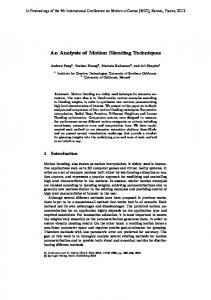
Directions in Computer Graphics
Plotting Pl tti Interactivity te act ty Real--Time Manipulation Real Image Image--Realism l (Photorealistic ( h l rendering) d ) Real--Time Rendering Real Scientific Visualization
History M ti t d by Motivated b hardware h d evolution l ti and d the th availability il bilit off new devices
1950's : First military applications of graphics
Whirlwind,, built in earlyy 50’s at MIT,, cost $4.5 $ million and could perform 40,000 additions/second.
1960's: Popularization of the storage tube by Tektronix direct--view storage direct storage--tube(DVST) display terminal DVST 9
$12,000 - $15,000
9
no refreshing is needed
9
high resolution w/o flicker
9
no partial erasing, no color mode
History
1963
Sketchpad interactive drawing system by Ivan Sutherland(MIT)
introduction of interactive computer graphics data structures for storing symbol hierarchies, interaction technique - keyboard and lightg -p pen light
Douglas Engelbart invents the mouse Steve Coons - Surface p patch technique q
Sketchpad in 1963. Note use off a CRT monitor, light l h pen and function-key panel.
History
Mid 1960s : Industry starts to use interactive computer systems but primary batch mode and too much cost 1970's : Turnkey systems and raster displays images 1977 - Apple II Early 1980s : Introduction of PC (Macintosh (Macintosh, IBM PC)
OOP paradigm UI such as Smalltalk80, Smalltalk80 Macintosh UI Workstations are more common Performance--price ratio takes off Performance
Mid 1980's : Emergence of graphics standards
History
Luxo Jr. Jr (1986) is the first three three--dimensional computer animated film to be nominated for an Academy Award
Late 1980's : Evolution of advanced GUI's and visualization environments
History
1990's
Low price, high performance Increasing demand for higher quality graphics GUI and other graphics intensive applications. applications 1995: Toy Story (Pixar and Disney), the first full length fully computer computer--generated 3D animation Since then : Toy Story (1995), A Bug's Life (1998) and Toy Story 2 (1999), (1999) and ... Late 90’s: interactive environments, scientific and medical visualization, artistic rendering, image based rendering, etc.
History
2000'ss 2000
PC, Natural interface using speech, gestures and facial expressions Real time photorealistic rendering on PC Ubiquitous computing Moved from texturetexture-mapped rendering to programmable pixel shading in pursuit of cinematic realism
History : shaded image
Since midmid-1970's : the development motivation has been photophoto-realism or TV image like a graphics image Photo--realism depends on how we calculate Photo light--object interaction light Local/Global reflection models
Groud shading (1971) Phong local reflection model(1975) :most popular ray tracing (1980) - specular interaction radiosity di it (1984) - diffuse diff interaction i t ti
Future of Computer Graphics
Wh t is What i CG? is i a wrong question ti Where it can be found? is better
CAD/CAM - 90% of cars are done using CG DTP - newspaper p p and magazine g GUI - do you use Windows...? Film effects - very attractive, but not important Games - i.e., $$$$ Video editing - Local TV studios, studios TV news, news Virtual reality reality-- CAD/CAM, visualization and many many more
How we draw, draw edit and save a picture
Read Chap. 15
Graphics File Formats
Image Image--File Configurations Color--Reduction Methods Color File--Compression Techniques File
ImageImage -File Configurations
Raw data (or Raw raster file)
Uncompressed raster raster--graphics file
Header of image file
Information about the structure of the file File size, depth, compression method, color range, background color,, etc. For compressed files, tables for decoding and display
ColorColor -Reduction Methods
Color--reduction Color
Uniform Color Reduction Popularity p y Color Reduction
Reduce the number of colors used in the display p y of an image g Replaces one discrete set of colors with a smaller set
Select the k most frequently occurring colors in the image file
Median--Cut Color Reduction Median
Subdivide the color space for the image file into k subregions
FileFile -Compression Techniques
Lossless compression vs. Lossy compression Run--Length Encoding Run
Store each sequence of repeated values as the single file value along with the number of repetitions {20, 20, 20, 20, 99, 68, 31, 40, 40, 40, 40, 40, 40, 40, 40, …} {4, 20, -3, 99, 68, 31, 8, 40, …}
FileFile -Compression Techniques
LZW Encoding
Replace the patterns with codes Substitutional algorithm or dictionarydictionary-based algorithm {128 96 {128, 96, 200 200, 30 30, 10 10, 128 128, 96, 96 50, 50 240, 240 200, 200 30, 30 10, 10 …}} {c1, c2, c1, c3, c2, …} or {c1, c2, c1, 50, 240, c2, …}
Other PatternPattern-Recognition Compression Methods
FileFile -Compression Techniques
Huffman H ff E Encoding di
Assign the shortest code to the most frequently occurring value, value and the longest code to the least occurring value
FileFile -Compression Techniques
Arithmetic Encoding
Frequency count is used to obtain numerical codes Boundary values for the subintervals are used to encode and decode the sequences within the file File Value
Frequency Count
File Fraction
A B C
16 24 40
0.20 0.30 0.50
Total
80
1.00
Sequence AA AB AC …
Unit-Interval Range 0.00 0 00 - 0.04 0 04 0.04 - 0.10 0.10 - 0.20
Sequence … CA CB CC
Unit-Interval Range 0.00 - 0.20 0.20 - 0.50 0.50 - 1.00
Unit-Interval Range 0.50 - 0.60 0.60 - 0.75 0.75 0 5 - 1.00 00
FileFile -Compression Techniques
Discrete Cosine Transform
Encoding
{215, 209, 211, 207, 192, 148, 88, 63} Î {471.29, 143.81, -67.76, 16.33, 7.42, -4.73, 5.49, 0.05}
D Decoding di
# of Terms 4 5 8
Inverse Discrete Cosine Transform Vales 212.63 215.26 215.00
211.85 209.23 209.00
211.53 208.91 211.00
207.42 210.04 207.00
188.43 191.06 192.00
147.65 145.02 148.00
95.47 92.84 88.00
58.02 60.64 63.00
Bit-Mapped vs. BitObjectObject-Oriented Graphics
Painting programs
bit-mapped representation bite.g., g , MacPaint
Drawing programs
object objectbj t-oriented i t d representation t ti e.g., AutoCAD
BitBit -Mapped Graphics
Paint Mode Bit--mapped memory - represent graphical images and Bit patterns by assigning a block of memory for the direct storage of the intensity patterns Objectiveness of a line line, polygon polygon, or brush stroke is lost Limitations
pixel democracy - all pixels are created equal once once, they are set in a bitbit-mapped image → slow modification no support of images requiring precision or numerical dimensioning device dependency
ObjectObject -Oriented Graphics
Draw Mode Mathematical representation of lines, rectangles, ovals, Bezier curves, and so on. Objectiveness is maintained
Objects designed may have a hierarchical structure Easily editable
Difficulties
more difficult diffi lt to t use no support of painting tools
Image g File Formats – Pixel Pixel-Mapped
GIF (Graphics Interchange Format)
the CompuServe Information Service and F&R Block Company copyrighted bitmap format uses compression can store only 256 256--color images, any size
9 9 megabyte for 1943x1702 24 9.9 24--bit RGB color image
PNG (Portable Network Graphics)
a royaltyroyalty-free GIF and LZW (maybe also TIFF) replacement Upto 48 bits/pixel superior lossless compression 6.5 megabyte for 1943x1702 24 24--bit RGB color image h http://www.libpng.org/pub/png/ // lib / b/ /
Image File Formats – Pixel Pixel-Mapped
TIFF (Tag (Tag--based Image File Format)
Aldus Corp. and Microsoft to support digital scanner manufacturers and desktop publishing systems to describe and store raster image data TIFF is a popular format for high color depth images, along with JPEG and PNG run--length encoding with compression (also LZW) run independent depe de of o OS, processors, p ocesso s, compilers, co p e s, a and d filing g systems sys e s become a standard for image storage and communication
Image File Formats – Pixel Pixel-Mapped
JPEG (Joint Photographic Experts Group)
international compression standard (1992) high compression rate can be acquired by removing the following redundancy in an image: spatial (between neighboring pixels), pixels) spectral (between color planes), temporal p (between ( adjacent j frames in a sequence) q ) highly lossy compression (in general, 5:1 and 15:1) But, objectionable blocking artifacts may occur. poor lossless compression efficiency (less than 3) lossy compression method is limited to input images with maximum bit depth of 8bits/pixel. lossless support 2 to 16 bits/pixel. no support for truetrue-color
JPEG artifacts
TIFF
JPEG
Image File Formats – Pixel Pixel-Mapped pp
JPEG 2000
new international compression standard (2002.1) roughly 20% on average higher compression efficiency than JPEG new functionalities:
integrated lossy/lossless compression region--of region of--interest(ROI) encoding Multi--resolution capability Multi Progressive transmission by pixel and resolution accuracy progressive p g decoding g etc.
JPEG 2000 Applications
Consumer applications such as multimedia devices (e.g., (e g digital cameras, personal digital assistants, 3G mobile phones color facsimile, phones, facsimile printers, printers scanners etc) Client/server communication (e.g., the internet, Image database, Video streaming, video server, etc.) Military/surveillance (e.g., HD satellite images, Motion detection, detect o , network et o d distribution st but o a and d sto storage, age, etc etc..)) Medical imagery (PACS) Storage of motion sequences (e.g., digital cinema, HD digital Camcorder). Remote sensing, digital libraries/archives, and E E-commerce.
Image File Formats – Pixel Pixel-Mapped
EPSF: Encapsulated PostScript File Format
Adobe Systems Incorporated importing and exporting PostScript language files grayscale g y or color usually ASCII No compression can be mix of raster and geometric data
Image File Formats – Pixel Pixel-Mapped (Comparison) BITS PER PIXEL
FILE SIZE
JPEG
24
TIFF
8,24
medium
GIF
1,4,8
medium
EPSF
1 2 4 8 24 1,2,4,8,24
small
huge
COMMENTS lossy, lossyy, good g for archives good no good for colorful images good for printing
Image File Formats – Object Object-Oriented
Store a description of how to draw the image CAD Fil File Formats F t
DXF/AutoCAD
AutoCAD de facto industry standard drawing exchange files
IGES (Initial Graphics Exchange Specifications)
ANSI standard used by W/S, minicomputer, and mainframes based CAD
DirectX Graphics vs. OpenGL
DirectX Graphics
Microsoft Mi ft Microsoft Windows
DirectX is better optimized for hardware 3D acceleration on the Windows platform
Latest version : Direct3D 10 Object j Oriented Programming g g friendlyy
COM and .NET based
OpenGL
SGI Multi--platform : An implementation is available on Multi most modern OS Latest version : OpenGL 2.1 21 Not Object Oriented (Includes and Libraries)
OpenGL 2 vs vs. Direct3D 9/10 OpenGL 2
Direct3D 9
Direct3D 10
O Operating ti S System t Support
Windows,, MacOS, BeOS, *nix, others
Wi d Windows (9 (9x, 2000,xp)
Windows Vista
API Specification
OpenGL Specification
SDK Documentation
SDK Documentation
API Mechanism
includes and libraries
COM
OS Integrated (WDDM Driver)
Source Implementation Available
Yes
No
No
O OpenGL GL 2 vs. Di Direct3D t3D 9/10 OpenGL Ope G 2
Direct3D ect3 9
Direct3D ect3 10 0
Fixed--Function Shaders Fixed
Yes
Yes
No
Programmable Shaders
Yes
Yes
Yes
Parametric Curve Primitives
Yes
Yes
Yes
Parametric Surface Primitives
Yes
Yes
Yes
Matrix
Row major order
Column major order
Column major order
Coordinate System
Left--handed Left
RightRighthanded
RightRighthanded
O OpenGL GL 2 vs. Di Direct3D t3D 9/10 OpenGL 2
Direct3D
Pros
Familiar to traditional C programmers Industrial standards
Can manage hardware resources di directly l Early adoption of new technologies and hardwares
Cons
Rigid specification Late adoption of new technologies Incompatibility between extensions of vendors
Strongly platform platform--dependent (Windows only) Hard to learn API and program an application
N tT Next Topics i
We have finished Chap 1 & 2. Next topic is how to find pixels corresponding to graphic primitives.