INTERNATIONAL CONFERENCE ON ENGINEERING DESIGN ICED 97 TAMPERE, AUGUST 19-21, 1997
FUNCTIONAL MODELLING USING AN OBJECT-ORIENTED DESIGN SYSTEM Dipl.-Ing. Horst Werner, Dr.-Ing. Michael Muth, Prof. Dr.-Ing. Christian Weber CAD, Functional Modelling, Feature-Based Design, Object-Oriented Design System
Introduction A significant progress in the development of CAD-systems was the extension to functionalities handling more than pure geometry (such as points, edges, surfaces and bodies), i.e. data concerning the technical product structure (such as physical and mechanical properties). These efforts are made to accelerate the engineering and design process, to avoid errors during the engineering process and to make use of the product-related data in electronic form in the later phases of the product life cycle. One approach to extend the CAD-functionalities is feature-based design, which aims at representing some apects of the product separately. Yet it is necessary to include the different kinds of features (describing different properties of the product) into a complete model. Despite the efforts of the institutes of standardization a satisfying product model has not yet been defined. A possible solution of this problem may be the definition of a meta-language for the engineer allowing him to build his own product model including his own characteristical entities of the product. This meta-language must be very simple to understand and to extend; the derived sentences (the instances of his product model) must be exchangable and combinable.The object-oriented concept and the different components (terminals or alphabet, non-terminals or symbols and deriving rules) of this meta-language are discussed in this paper.
Design Objects A product normally shows a hierarchical structure of sub-units. Each of those sub-units should be represented by its own complete model describing its condition as well as its behaviour. The condition of a unit includes its geometry and physical properties, the forces and momenta acting upon it, its position, speed and acceleration etc. All these can be expressed as physical quantities. Thus a description of an object’s condition is given by a number of parameters, or, more general, by data. The behaviour of an object is given by the interdependences of these parameters, for example of acceleration, mass and force. The instructions for the combination of the data will − in accordance with the terminology used in Object Oriented Programming − be called methods.
The integration of data and methods leads to a complete model called Design Object. We may distinguish between data describing the permanent properties (like geometry, mass etc.) and data describing a temporary state of the object (position, forces). While the permanent properties can only be modified by methods related to the dimensioning process, the temporary state of the object is changed by the methods describing its functional behaviour. A third kind of methods may only read the data and produces an output suitable for further processing, e.g. the generation of technical drawings, part lists, FE-models, NC programs etc. The most efficient representation for the methods describing the dimensioning process and the functional behaviour are equations and unequations. For: • Equations are a „programming language“ that is familiar to any engineer. • One equation is capable to answer many different questions depending on which of the variables are given and which is unknown.
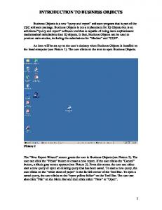
Interface Objects While the Design Objects give a full description of the single sub-units, we also need to describe the interaction between these sub-units in a compound. If two sub-units influence each other, that is if a direct mechanical, electrical, thermal or other connection exists between them, certain data of the Design Objects are coupled to each other. In the area of mechanics for instance, Newton’s 3rd axiom (actio = reactio) demands that the normal force on a contact surface has the same value for both of the bodies. The object oriented product model describes these dependences by the means of Interface Objects, who define a set of parameters that must be equal for two Design Objects connected by the interface. Thus it is possible to represent two basic types of interaction: on the one hand energy transmission in mechanical, electrical or any other form, and on the other hand geometric dependences (like the equality of the diameter of a shaft and a bearing mounted on it).
Figure 1: Design Object and Interface Objects
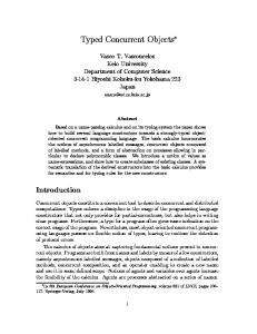
Composition of Design Objects When several Design Objects are joined to form a new, more complex Design Object, the coupling of their parameters by means of the Interface Objects leads to an equation system describing the new Design Object’s behaviour. Properties of the whole object which are not included in the sum of the parts may be modelled by additional data and methods. The interfaces of the resulting Design Object are those interfaces of its parts that are not internally connected. The parts on the whole remain independent units; they are linked to the composed Design Object (which has direct access to its parts’ data) by the relations „is part of“ and „consists of“. These relations define the products modular hierarchy.
Figure 2: Composed Design Object
Abstraction Levels When we mentioned the word „object“ in the text above, we implicitly talked about an object class, for an infinite number of instances of such an object can be created by assigning values to the permanent parameters. They all have the same structure and behaviour described by the more abstract object class. The object classes themselves also may be further generalized to base classes, thus an abstraction hierarchy is created by the relations „is a particular case of“ and „is a generalization of“. This allows the use of the inheritage mechanisms which is well known in the field of Object Oriented Programming. It means that a special case of an existing base class can be created simply by adopting all its properties and adding the specifically required data elements and methods (and, sometimes, by redefining some of the original methods). This means that common properties of similar Design Objects must only be defined once. For example, the mechanical and geometric properties of a bolt with cylindrical and a bolt with
hexagonal head are mostly the same. Thus it would be sensible to define a base class „bolt“ which must only be slightly modified to obtain one of the mentioned particular bolts. Further generalization leads to a „Black Box“ that only represents the function „transmission and storage of translational mechanical energy“. This enables the design engineer to build a functional structure and make (widely automated) calculations without committing himself to the concrete realisation of the partial functions. Thus he has a powerful tool that supports the whole process of gradually decreasing the abstraction level and allows him to reuse the data calculated in the previous steps. In this respect one might see similarities to the chromosome model described in [Andreasen 1992].
Possible Applications The modular concept of Design Objects is especially suitable for creating a construction set of machine elements. These may be easily exchanged and modified to represent new specific aspects of a product. The Interface Objects enable the design engineer to simply put together a product using a database of Design Objects describing standard machine elements. If he has to design a completely new product, he may first build a functional structure of Black Boxes, examine their behaviour in the compound and then replace them gradually by more concrete derived object classes. New Design Objects can easily be derived them from one or more base classes (this allows the fast generation of Design Objects describing parts with several integrated functions) and adding or modifying some parameters and equations. When the structure of the product is modelled, it can be stored in the database as a new Design Object. Now the dimensioning process can be carried out widely automatically by the design system. Thus the design of a product family with the same structure and different boundary conditions becomes very easy. Finally, the product’s description in form of drawings, part lists etc. may also be generated automatically in electronic form. A sample implementation for modelling and dimensioning using the object-oriented model is being programmed at the chair for engineering design (LKT) in Saarbrücken. References Muth, M., „Repräsentation von Konstruktionswissen unter Verwendung des objektorientierten Paradigmas“, Dissertation, Lehrstuhl für Konstruktionstechnik/CAD , Universität des Saarlandes, Saarbrücken, 1994 Werner, H., „Konzept eines objektorientierten Konstruktionssystems zur integralen Modellierung von Standardteilen und -baugruppen.“ Diplomarbeit, Lehrstuhl für Konstruktionstechnik/CAD , Universität des Saarlandes, Saarbrücken, 1996 Andreasen, M.M., „Designing on a Designers Workbench“, Proceedings WDK, Rigi, 1992 Contact address Dipl.-Ing. H. Werner Lehrstuhl für Konstruktionstechnik/CAD Universität des Saarlandes, Postfach 15 11 50 Im Stadtwald, 66041 Saarbrücken, Germany
Telefon: +49 681 / 302-3387, Telefax: +49 681 / 302-4858 e-mail:
[email protected]