Jan 31, 2011 - Inert gas â N. 2 or Ar. 1.b. ALD â Basic principle and Growth Mechanism .... 3. /Si. Chipworks. DRAM Capacitor Roadmap â Samsung vs. ITRS ...
Introduction to ALD Lab Dresden and Atomic Layer Deposition PROGRAM
© Fraunhofer
Introduction to ALD Lab Dresden and Atomic Layer Deposition PROGRAM 1. Introduction to Atom ic Lay er Depos ition a. ALD – Historical background / Hall of Fame b. ALD – Basic principle and Growth Mechanism c. ALD Reactors / Productivity Improvements d. ALD Processes for Logic and Memory Applications 2. Introduction to ALD Lab Dres den a. Background, Mission/Vision, Competences, Applications, … b. Fraunhofer CNT ALD Application Lab
© Fraunhofer
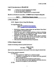
1.a. ALD – Historical background / Hall of fame Prof. V.B. Ales kov s kii (left) Proposed the concept of the ALD in his Ph.D. thesis published in 1952. Prof. S .I. Kol’ts ov (right) First publications as “Molecular Layering” in the early 1960s from Leningrad Technological Institute (LTI). Dr. Tuomo Suntola (right) Demonstrated ALD 1974 at Instrumentarium Oy, Finland Patented ALD (ALE) 1977 T. Suntola, "Methods for producing compound thin films", US patent 4058430
S v en Lindfors (left) Constructing ALD R&D and production tools since 1975 (Lohja Oy, Mikrokemia Oy, ASM Microchemistry Ltd., Picosun, …) © Fraunhofer
1.b. ALD – Basic principle and growth mechanism Atomic layer deposition (ALD) is a thin film deposition technique that is based on the sequential use of a gas phase chemical process. Reactant A
Purge 1
Reactant B
Purge 2
Reactions occur at the surface Self-limiting growth process: gas-surface reactions occur until surface is saturated. © Fraunhofer
Films are very uniform, smooth Precise thickness control Exact stoichiometry control Low contamination Conformal films in high aspect ratio structures
1.b. ALD – Basic principle and Growth Mechanism
Ex am ple:
Metal chloride / H2O process, e.g. AlCl3/H2O Al2O3
T: 200-500 °C P: 0.1-10 Torr
Inert gas – N2 or Ar Surface saturated
by –OH groups
© Fraunhofer
1.b. ALD – Basic principle and Growth Mechanism
1) Reactant A : Metal precurs or puls e Metal precursor is pulsed into the reactor, e.g. AlCl3.
© Fraunhofer
1.b. ALD – Basic principle and Growth Mechanism
1) Reactant A : Metal precurs or puls e The metal precursor reacts with surface -OH groups and chemisorbs to the surface, while leaving by-products to the gas phase, e.g. HCl.
© Fraunhofer
1.b. ALD – Basic principle and Growth Mechanism
1) Reactant A : Metal precurs or puls e The pulse continues until the surface reaction is saturated.
© Fraunhofer
1.b. ALD – Basic principle and Growth Mechanism
2) Purge 1 The reactor is purged with an inert gas, e.g. N2 or Ar, to remove by-products and unreacted metal precursor
© Fraunhofer
1.b. ALD – Basic principle and Growth Mechanism
2) Reactant B : Ox idizing precurs or puls e The oxidant precursor (H2O) is pulsed into the reactor and reacts with the chemisorbed metal precursor leaving by-products in the gas phase (HCl).
© Fraunhofer
1.b. ALD – Basic principle and Growth Mechanism
2) Reactant B : Ox idizing precurs or puls e The pulse continues until the surface reaction is saturated. Common oxidant precursors: H2O, H2O2, N2O O3, O2+, ...
© Fraunhofer
1.b. ALD – Basic principle and Growth Mechanism
4) Purge 2 The reactor is purged once again with an inert gas to remove by-products and unreacted oxidizing precursor.
© Fraunhofer
1.b. ALD – Basic principle and Growth Mechanism
Growth rate
Condensation
Decomposition
Process “Mono layer” Ideal case
Window Activation
Desorption
Growth temperature
© Fraunhofer
1.b. ALD – Basic principle and Growth Mechanism Decomposition
Growth rate
Condensation Process
“Mono layer” In reality
Window Desorption
Activation
Any combination possible
Growth temperature Thickness control
Precursor dose
© Fraunhofer
Conformal growth Step coverage
ALD Thickness
Growth Rate
Saturation
Number of deposition cycles
CVD
PVD Deposition rate
1.c. ALD Reactors / Productivity Improvement
a
b
ALD reactor ty pes : (a) showerhead type single wafer ALD
c
(b) reactor batch ALD reactor (c) in-line spatial ALD reactor as designed by SoLayTec (d) in-line spatial ALD reactor as designed by Levitech
d
e
© Fraunhofer
f
(e) roll-to-roll ALD reactor as designed by Lotus Applied Technology (f) roll-to-roll ALD reactor as designed by Beneq
J A van Delft et al 2012 Semicond. Sci. Technol. 27 074002 http://iopscience.iop.org/0268-1242/27/7/074002/article
ALD Batch Processing for Low Cost of Ownership
No Depletion Effect
Injectors
Gas Inlet Bottom
AS M A412
DRAM Capacitors, Logic HKMG BENEQ TFS 600 Encapsulation for OLED
© Fraunhofer
Fast ALD for Passivation of c-Si solar cells
S olay Tec
Ultrafast ALD for Al2O3 deposition Passivation of c-Si solar cells Efficiency increase of up to 1% absolute
Adv antages : Atmospheric process Deposition rate up to 10 nm/s (complete system) Uniformity < 3.0% wiw, < 4.0% wtw Throughput up to 3600 wph
© Fraunhofer
Spatial ALD for Wafer processing Atom ic Lay er Depos ition Carous el With Continuous Rotation And Methods Of Us e J Yudovsky - US Patent 20,120,225,195, 2012
© Fraunhofer
Roll to Roll ALD – BENEQ WCS 500
© Fraunhofer
1.c. ALD Processes for Logic and Memory Applications BEOL Cu Barrier/S eed IBM IEDM 2011
Mem ory
PVD/CVD TaN/Ta RuTa TaN + Co MnOx
Imec 2009
Samsung Stacked DRAM MIS
FEOL HKMG Technologies
90 nm 2004
Liners/Spacers Intel 45 nm 2007
S/D Contacts Double Patterning ASM PEALD SiO2
AMD 32nm 2011
Infineon DT DRAM Double Patterning © Fraunhofer
70 nm 2005
DRAM Capacitor Roadmap – Samsung vs. ITRS Year EOT JA 10-9A/cm2 High-k
2008
2010
0.9 0.8 0.6 107.9 111.3 148.4 HfO2 / ZrO2 / Al2O3
Bottom electrode Half-pitch (nm) High-k Aspect Ratio
2009
TiN
2012
0.4 0.3 222.6 242.8 ATO / STO / BST
Ru / RuO2 / Pt/ IrO2 / SrRuO
57
50
45
36
25
22
38.3
35.4
36.9
57.6
Chipw orks 2004 S am s ung's 90 nm First use of ALD for DRAM 512-Mb DDR SDRAM MIS TiN/HfO2/Al2O3/Si
© Fraunhofer
2015
DRAM Capacitor Roadmap – Samsung vs. ITRS Year EOT JA 10-9A/cm2 High-k
2008
2009
2010
0.9 0.8 0.6 107.9 111.3 148.4 HfO2 / ZrO2 / Al2O3
Bottom electrode Half-pitch (nm) High-k Aspect Ratio
TiN
2012
2015
0.4 0.3 222.6 242.8 ATO / STO / BST
Ru / RuO2 / Pt/ IrO2 / SrRuO
57
50
45
36
25
22
38.3
35.4
36.9
57.6
Chipw orks
2011 S am s ung 20/30-nm DRAM TiN/ZrO2 based/TiN
6F2 Ti-? (likely TiN)-gate buried wordline * Samsung’s 3x DDR3 SDRAM – 4F2 or 6F2? You Be the Judge.. © Fraunhofer
Posted on 1/31/2011 Chipworks Blog, Dick James
DRAM Capacitor Roadmap – Samsung vs. ITRS Year
2008
2009
2010
2012
2015
EOT 0.9 0.8 0.6 0.4 0.3 [ImecJAreported 2010] “… a record low10-9A/cm2 at IEDM 107.9 111.3 148.4 222.6 242.8 leakage MIM capacitors, JGHfO of 210-6 at High-k / ZrOA/cm2 ATO / STO / BST 2 / Al2O3
0.4nm EOT, enabling to scale DRAM to the 2x nm Bottom electrode TiN Ru / RuO / Pt/ IrO2 / SrRuO node. The capacitors were realized using a novel2 Half-pitch (nm) 57 fabricated 50 in a 45 36 TiN/RuOx/TiOx/STO/TiN stack 300mmHigh-k line with DRAM compatible processes.” Aspect Ratio
22
38.3
35.4
Chipw orks
2011 S am s ung 3x -nm S DRAM TiN/ZrO2 bas ed/TiN © Fraunhofer
36.9
25 57.6
DRAM Capacitor Roadmap – Samsung vs. ITRS Tighter pitch
MIM Capacitor Challenges : High-k CET Improvement ~0.6-0.7 nm
Thinner than 6 nm
3x nm TiN/ZrO2 /TiN bas ed
2x nm TiN/ZrO2 /TiN bas ed
1x nm
Forget about STO etc.
Not(!) S TO bas ed
Electrodes
Taller capacitor
Wf well above 5