INTRODUCTION TO DIRECT. DIGITAL SYNTHESIS. In a DDS System all the
parameters of the waveform: Frequency,. Phase, & Amplitude are defined by
digital ...
Application Note 101
INTRODUCTION TO DIRECT DIGITAL SYNTHESIS Technical Staff March, 1990 Revised June, 1991
amplitude word in a Look-up Table (LUT). Figure 1 shows a basic DDS system.
Basic Theory
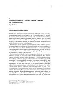
The usual desired output from a synthesizer is a sinusoidal waveform. However, any waveform can be generated using DDS provided that the highest Fourier component is within the Nyquist limitation (1/2 the clock frequency). This discussion will concentrate on the sinusoidal waveform, however. For any repetitive waveform there is a one-for-one correspondence between values of phase and values of amplitude. This one-for-one conversion is easily realized using a ROM. Within the ROM is stored a look-up table. The phase information is applied to the address bus and the amplitude information appears on the data bus. Each discrete phase point corresponds to a discrete amplitude value. The relationship is a trigonometric function, in this case a sine or cosine. The look-up table can be considered a digital phase-to-amplitude
Perhaps the easiest way to understand how DDS systems work is to explain the system from the output back toward the frequency control input. We will begin with the familiar analog RF signal and work backward through the digital system. The digital information provided to the DAC must represent the instantaneous amplitude value of the RF waveform. The digital section of a DDS system is concerned with generating this sinusoid oscillating digital number. The most efficient and flexible known method of generating this oscillating amplitude number is to first digitally define a frequency number. The frequency number is then digitally integrated in an accumulator to provide instantaneous digital phase information. Finally, the digital phase word is converted to the digital NCO PHASE ACCUMULATOR
CLOCK
LOOK-UP TABLE
DAC
ALIAS FILTER
RF OUTPUT
FREQUENCY CONTROL
In a DDS System all the parameters of the waveform: Frequency, Phase, & Amplitude are defined by digital words The first Analog Signal appears at the DAC output
Figure 1. Basic DDS System
Intel Corporation 1
11111111 11111111
DATA BUS
Data Bus
00000000
00000000
Address ADDRESS BUS Bus
11111111 11111111
Look up table showing the 90° sinusoid relationship between the address and data buses
Figure 2. 90 ° Look-up Table
converter. Figure 2 shows the relationship between address and data bus numbers in a typical look-up table ROM. All the sinusoidal amplitude information necessary for a complete 360° cycle is contained in 90° of information. Therefore, only 90° of mapping is required in the look-up table. The phase accumulator simply clocks in both directions and then reverses sign of the amplitude for the other 180°. This allows more economy in the look-up table ROM. All Stanford Telecom NCO families use 90° look-up tables. For a constant frequency w, df/dt will be constant. The phase change of a constant frequency signal is a linear progression. Digital accumulators are excellent generators of linear progressions of digital numbers. Indeed, the linearity of the time progression is simply dependent upon the time integrity of the clock. Different w values require different slopes of phase (df/dt) output. This is achieved by adding different values to the phase accumu-
Application Note 101
lator each cycle of the clock. The lowest frequency that can be generated occurs when just 1 LSB (least significant bit) is added to the accumulator which then increments through all possible states, one at a time. This will take 2N clock cycles for an N-bit accumulator, resulting in an output frequency of fclk / 2N. It is easy to see that adding any number M to the accumulator each cycle of the clock results in the accumulator count incrementing M times as fast, so that the frequency of the sinewave generated will be M* fclk / 2N. Since the number M represents the phase increment in each cycle it is generally referred to as Delta-Phase (Df). Thus the output frequency of an NCO is represented by the equation: fout =
Df * fclk 2N
A typical value for N in practice is 32, giving a resolution of 1 part in 2 32, or 4.29 * 109. This translates to a resolution of 12 milli-Hz at a clock frequency of 50 MHz or 0.23 Hz at a clock frequency of 1 GHz. All three parameters of the waveform; frequency, phase, and amplitude (w, f, and A) are defined by digital words. Frequently the resolution of these three parameters is confused. w resolution is determined by the number of bits in the phase accumulator. f resolution is determined by the number of bits in the ROM look-up table. Amplitude resolution is determined by the resolution of the DAC. A frequently asked question is; how can you achieve 48 bit frequency resolution using only an 8 bit DAC? The answer is that the DAC is simply approximating the ideal amplitude value for a given clock cycle. The resolution of the DAC will determine the am-
plitude accuracy of the desired waveform, not the frequency of the waveform. A one bit DAC can be represented by the MSB output of the phase accumulator. The output of the MSB will be a rectangular waveform. The spectrum of this digital waveform shows the most prevalent component to be the desired output frequency! As might be expected, as more bits are added, the output spectrum becomes progressively cleaner. The frequency of this most prevalent spectral component is adjustable with 2N resolution although its amplitude resolution is only one-bit.
Comparison with PLL Synthesizers
The technique of direct digital synthesis (DDS) has recently become a viable alternative or complement to phase-locked loop (PLL) synthesis for a wide range of applications. The DDS technique circumvents the traditional trade-offs associated with PLL architectures. Rather, a new set of trade-offs appear: Trade-offs for PLL Synthesizers 1. Frequency resolution (step size) 2. Settling time 3. Tuning range (bandwidth) 4. Phase noise (spectral purity) 5. Cost, complexity and power consumption Trade-offs for DSS Synthesizers 1. Clock speed (bandwidth) 2. Spurious responses (spectral purity) 3. Cost, complexity and power
Intel Corporation 2
consumption A comparison of these two trade-off lists implies a preference for one architecture or the other for a given application or specific design criteria. In DDS systems the frequency resolution is determined primarily by the word length of the phase accumulator. Furthermore, in DDS systems the settling time is usually determined by the bandwidth of the alias filter. Consequently, frequency resolution, settling time, and spectral purity are independent variables, unlike PLLs where they are interrelated. It is important to distinguish between settling time and latency. Settling time is defined as the time a signal settles on a new frequency after being switched from an initial frequency. Latency is defined as the number of clock cycles from when a new value of Df is loaded into the NCO until the output signal switches to the corresponding frequency. Latency will be determined by the architecture used within the NCO device. The actual latency time can be calculated by multiplying the period of the clock by the latency clock cycles. A few more clock cycles must be added to account for delays in the DAC and other possible signal processing steps, such as multipliers used for AM. In DDS systems the important trade-off is between bandwidth and spectral purity. This trade-off can manifest itself in several ways. If the clock speed is reduced, the Nyquist frequency is consequently reduced, and thus the bandwidth is also reduced. Lower clock frequencies allow for higher resolution DACs which can provide better spectral purity. Alternatively, higher clock speeds can be used in conjunction with frequency dividers. Dividing the DDS output frequency will reduce the bandwidth but also improve
Application Note 101
spectral purity. Both DDS and PLL system performance can be improved by careful design, higher quality components, using more power to achieve higher speeds, and of course, spending more money. DDS should not be regarded as a direct replacement for PLL circuits. Rather, both techniques have inherent advantages and disadvantages in specific systems. DDS systems usually require relatively high power consumption, with almost one watt being a state-of-the-art minimum. However, there are many specific synthesizer design objectives which render the DDS architecture quite attractive. Some of these include: 1. Minimum settling time (submicrosecond) 2. Multi-octave operation 3. Fine or very fine frequency resolution (