NPTEL >> Mechanical Engineering >> Modeling and Control of Dynamic electro-
Mechanical System. Module 1- Lecture 1. Introduction to Dynamic System ...
NPTEL >> Mechanical Engineering >> Modeling and Control of Dynamic electro-Mechanical System
Introduction to Dynamic System Modelling
Dr. Bishakh Bhattacharya Professor, Department of Mechanical Engineering IIT Kanpur
Joint Initiative of IITs and IISc - Funded by MHRD
Module 1- Lecture 1
NPTEL >> Mechanical Engineering >> Modeling and Control of Dynamic electro-Mechanical System
The Lecture Contains
Introduces a few Controlled Dynamical Systems d f ll d l Modelling of a Dynamical System g y y Presents two Dynamic Systems for Mathematical Modeling namely: Modeling namely: A Cruise Control System A Disk Reading System
Joint Initiative of IITs and IISc - Funded by MHRD
Module 1- Lecture 1
NPTEL >> Mechanical Engineering >> Modeling and Control of Dynamic electro-Mechanical System
Module 1- Lecture 1
Course Introduction •
•
•
•
Electro-mechanical systems are ubiquitous today. Starting from an Intelligent W hi Machine Washing M hi that th t determines d t i washing hi span off garments t on it’s it’ own to t Rockets and Un-manned Vehicles that determines it’s course of flight autonomously – our world is full of such autonomous dynamic systems today. Due to the mind boggling variety of such examples that we come across – a systems approach is highly needed to understand the nature of such systems and predict dynamic response. In order to design and develop an autonomous system, you need to have knowledge g of two fundamental subjects j – dynamical y systems y and feedback control. While, the first helps you in terms of understanding the response of the system under various mechanical and electrical inputs; the knowledge of feedback control helps you to develop autonomous systems that can follow a set of desired commands or g generate a desired response p or output. p In this lecture, I will give you the glimpses of an array of applications in which we have applied this concept. This will help you to understand where you can possibly apply the knowledge that you will acquire in this field
Joint Initiative of IITs and IISc ‐ Funded by MHRD
3
NPTEL >> Mechanical Engineering >> Modeling and Control of Dynamic electro-Mechanical System
Module 1- Lecture 1
EXAMPLE 1: Next Generation: Controllable Antenna
Antenna with Muscle Wire
Deformed Antenna after triggering the Muscle Wires
Shape of an antenna could be controlled by controlling the tension in the “muscle wires”. Muscle wires made of Shape Memory Alloy (SMA) gets shortened if heated y In this p process, an wire of diameter 350 micro‐meter could ggenerate byy electricity. force up to 10N. Using this technology, one can control the transmission pattern from an antenna Joint Initiative of IITs and IISc ‐ Funded by MHRD
4
NPTEL >> Mechanical Engineering >> Modeling and Control of Dynamic electro-Mechanical System
Module 1- Lecture 1
A Beam Deformation by SMA Wire Note: As we pass current into the SMA wire, due to phase Note: As we pass current into the SMA wire due to phase transformation it gets shortened which will produce a couple on the stiffener beam and bend it. By controlling the current in the SMA wire – you can control this bending.
Joint Initiative of IITs and IISc ‐ Funded by MHRD
5
NPTEL >> Mechanical Engineering >> Modeling and Control of Dynamic electro-Mechanical System
Module 1- Lecture 1
Schematic of the Controllable Antenna System
Analog to Digital Conversion Analog to Digital Conversion
Note: In this system there are two sensors: (a) Strain Gauge Sensor (used for sensing the strain which can be converted to deflection and (b) Laser Displacement Sensor (Opto NCDT); the , muscle wires are Flexinol SMA, which can be classified as actuators. Joint Initiative of IITs and IISc - Funded by MHRD
NPTEL >> Mechanical Engineering >> Modeling and Control of Dynamic electro-Mechanical System
Module 1- Lecture 1
EXAMPLE 2: Satellite Ultra quiet Isolation Technology Experiment (SUITE) Consider the top‐part designed for vibration isolation
Satellite has a highly sensitive payload, which must be saved from tremendous vibration that gets generated in a satellite launching vehicle. Vibration isolators are used for t llit l hi hi l Vib ti i l t df this purpose. Joint Initiative of IITs and IISc - Funded by MHRD
NPTEL >> Mechanical Engineering >> Modeling and Control of Dynamic electro-Mechanical System
Module 1- Lecture 1
Detailed Description p of the Vibration Isolator
One such isolator is known as h l k Active Stewart Platform Here, the isolation is achieved , by controlling the leg‐lengths of six‐links with the help of piezoelectric actuators
Joint Initiative of IITs and IISc ‐ Funded by MHRD
8
NPTEL >> Mechanical Engineering >> Modeling and Control of Dynamic electro-Mechanical System
Module 1- Lecture 1
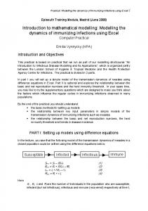
EXAMPLE 3: A Drug Infusion Control System
An autonomous drug infusion control system could solve a very challenging problem of hospitals of our country where the number of nurses are too few in comparison to the number of patients. This system is envisaged to control the flow of various drugs and nutrients to patient’s body autonomously and send an warning to the nurse when the supply gets over.. Joint Initiative of IITs and IISc - Funded by MHRD
NPTEL >> Mechanical Engineering >> Modeling and Control of Dynamic electro-Mechanical System
Module 1- Lecture 1
Concept Detailing of a Smart Drug Infusion System The challenge of this project is to design a smart intravenous drug infusion system free from roller clamp with high visibility clamp with high visibility medicine level indicators and sound indicators which can be easily operated with remote controll
This is a novel concept in which essentially flow from a tube is controlled with the help of an micro‐actuator (shown as a green compliant system). The system is controlled f i (h li ) h i ll d using wire‐less communication. Joint Initiative of IITs and IISc - Funded by MHRD
NPTEL >> Mechanical Engineering >> Modeling and Control of Dynamic electro-Mechanical System
Module 1- Lecture 1
AC Closer ose look oo of o the t e Compliant Co p a t Mechanism ec a s
Joint Initiative of IITs and IISc ‐ Funded by MHRD
11
NPTEL >> Mechanical Engineering >> Modeling and Control of Dynamic electro-Mechanical System
Module 1- Lecture 1
Did d you notice ot ce a Co Common o Pattern? atte
In all these examples, the structures – Dynamical Systems like Antenna, Isolator and Drug Infusion System are controlled by the Actuators based upon commands from th C t l S t the Control System which has taken decisions based on an array of Sensors. hi h h t k d i i b d fS Joint Initiative of IITs and IISc ‐ Funded by MHRD
12
NPTEL >> Mechanical Engineering >> Modeling and Control of Dynamic electro-Mechanical System
Module 1- Lecture 1
Modelling a Dynamical System Models are mathematical representations of system dynamics Models allow the dynamics to be simulated and analyzed, without physically building the system. Models are simplified form of the system and hence are never ‘exact’! Models can be used in describing the ways in which a system can perform. Certain types of analysis (e.g., parametric variations) can’t easily be done on the h actuall system b but can b be simulated i l d through h h system models d l Models can be run much more quickly & thus saves developmental time A single system may have many models
Joint Initiative of IITs and IISc - Funded by MHRD
NPTEL >> Mechanical Engineering >> Modeling and Control of Dynamic electro-Mechanical System
Module 1- Lecture 1
Choice of inputs and outputs depends on point of view Inputs: These are the parameters that are external to the model that you are building Inputs in one model might be outputs of another model (e.g., output of an antenna controller provides input to the antenna model) Outputs: Physical variables (often states) that one can measure Choice of outputs depends on what we intend to sense and what parts of the component model interact with other component models States: Chosen such that their values at a reference time and the corresponding inputs are known. May or may not include Outputs.
Joint Initiative of IITs and IISc - Funded by MHRD
NPTEL >> Mechanical Engineering >> Modeling and Control of Dynamic electro-Mechanical System
Module 1- Lecture 1
Assumptions p in a Model •
There are two types of assumptions – implicit and explicit assumption
•
Implicit assumptions are generally universally known and hence rarely stated – for example, use of continuum model , earth as inertial reference frame etc.
•
Explicit assumptions are stated in the beginning of establishing a mathematical relationship.
•
In this course we will explicitly assume that the dynamic systems to be modelled are Linear and Time Invariant (LTIV) in nature. In simple terms, this would imply that the dynamic systems will be modelled as a set of ordinary differential equations (neglecting the non-linear effects) and also the coefficients in such governing equations are constant.
Joint Initiative of IITs and IISc ‐ Funded by MHRD
15
NPTEL >> Mechanical Engineering >> Modeling and Control of Dynamic electro-Mechanical System
Module 1- Lecture 1
A syste system is s modeled ode ed e either t e by defining the input-output characteristics or by selecting a set of state variables
Inputs describe the external excitation of the dynamics . Inputs are extrinsic t i i to t the th system t dynamics d i ((externally t ll specified) ifi d) . C Constant t t inputs are often considered to be parameters Outputs p are variables that are to be calculated or measured Input-output relation is often governed by a generalized ODE of the form any(n)+…..+a2y(2)+a1y(1)+aoy=bmu(m)+….+b1u(1)+bou(t) Where y(n)= dny/dt /dtn, u(m)=d(m)u/dt /dtm Joint Initiative of IITs and IISc - Funded by MHRD
NPTEL >> Mechanical Engineering >> Modeling and Control of Dynamic electro-Mechanical System
Module 1- Lecture 1
Consider a Cruise Control Model:
U
The car above is travelling at a speed u. Neglecting excitations due to road undulations etc. can y you find out the g governing g Equation of Motion (EOM)? Can you find out the input-output relationship from the EOM?
Joint Initiative of IITs and IISc - Funded by MHRD
NPTEL >> Mechanical Engineering >> Modeling and Control of Dynamic electro-Mechanical System
Consider the Disk Reading System
Non-collocated sensing
Can you find out the Governing Equation of Motion? Can you find out the relationship between the Torque and Angular Displacement?
Joint Initiative of IITs and IISc - Funded by MHRD
Module 1- Lecture 1
NPTEL >> Mechanical Engineering >> Modeling and Control of Dynamic electro-Mechanical System
Module 1- Lecture 1
General Reference Books Feedback Control of Dynamic Systems – Franklin, Powell and Naeini, Pearson Education Asia Advanced Control Systems – Dorf and Bishop, Pearson Education Asia Control Systems Engineering – Norman S Nise, John Wiley & Sons Modern Control Engineering – K. Ogata, Prentice Hall Mechatronics: Electronic Control Systems in Mechanical and Electrical Mechatronics: Electronic Control Systems in Mechanical and Electrical Engineering – W. Bolton, Prentice Hall Handbook of Sensors and Actuators f ‐ Elsevier, series editor: P. P. Regtien
Joint Initiative of IITs and IISc ‐ Funded by MHRD