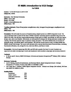
Introduction to VLSI Testing.20. Testable Design. • Design for testability (DFT). •
ad hoc techniques. • Scan design. • Boundary Scan. • Built-In Self Test (BIST).
Introduction to VLSI Testing 李昆忠 Kuen-Jong Lee Dept. of Electrical Engineering National Cheng-Kung University Tainan, Taiwan, R.O.C.
Introduction to VLSI Testing.1
Problems to Think
• A 32 bit adder • A 32 bit counter with RESET function • A 1MB cache memory • A 107-transistor CPU
Introduction to VLSI Testing.2
OUTLINE • Introduction • Fault modeling • Fault simulation • Test generation • Automatic test pattern generation (ATPG) • Design for testability • Built-in self test • Synthesis for testability • An example
Introduction to VLSI Testing.3
Testing: To tell whether a system is good or bad Vdd
0
0 0/1
0
0 0
Related fields Verification: To verify the correctness of a design
Diagnosis: To tell the faulty site Reliability: To tell whether a good system will work after some time.
Introduction to VLSI Testing.4
Importance of testing N = # transistors in a chip p = prob. (a transistor is faulty) Pf = prob. (the chip is faulty) Pf = 1- (1- p) N If p = 10-6 N = 106 Pf = 63.2%
Introduction to VLSI Testing.5
Difficulties in Testing • Fault may occur anytime -
Design Process Package Field
• Fault may occur at any place
Vdd
Vss
• VLSI circuit are large - Most problems encountered in testing are NP-complete
• I/O access is limited Introduction to VLSI Testing.6
How to do testing from Designer’s points of view • Circuit modeling • Fault modeling
Modeling
• Logic simulation • Fault simulation • Test generation
ATPG
• Design for test • Built-in self test
Testable design
• Synthesis for testability Introduction to VLSI Testing.7
Circuit Modeling • Functional model--- logic function - f(x1,x2,...)=... - Truth table
• Behavioral model--- functional + timing - f(x1,x2,...)=... , Delay = 10
• Structural model--- collection of interconnected components or elements A B
E 1 0
C D
1 0
G
0 F
Introduction to VLSI Testing.8
Levels of Description • Switch level
• Circuit level
VDD
C
C 4 B
VDD
VDD
C 1
C3
C2 E
• Gate level A B
• Higher/ System level
E G
C D
F
Introduction to VLSI Testing.9
Fault Modeling • The effects of physical defects • Most commonly used fault model: Single stuck-at fault A B
E
A s-a-1 B s-a-1 A s-a-0 B s-a-0
C s-a-1 D s-a-1 C s-a-0 D s-a-0
E s-a-1 F s-a-1 E s-a-0 F s-a-0
G s-a-1 G s-a-0
G C D
F
14 faults
• Other fault models: - Break faults, Bridging faults, Transistor stuck-open faults, Transistor stuck-on faults, Delay faults
Introduction to VLSI Testing.10
Fault Coverage (FC) # faults detected FC = # faults in fault list Example: a b
1 0
6 stuck-at faults ( a0,a1,b0,b1,c0,c1 )
c1
0
1 0
Test {(0,0)} {(0,1)} {(1,1)} {(0,0),(1,1)} {(1,0),(0,1),(1,1)}
faults detected c1 a1,c1 a0,b0,c0 a0,b0,c0,c1 all
FC 16.67% 33.33% 50.00% 66.67% 100.00%
Introduction to VLSI Testing.11
Testing and Quality IC Fabrication
Shipped Parts Testing Yield: Fraction of good parts
Quality: Defective parts per million (DPM) Rejects
• Quality of shipped parts is a function of yield Y and the test (fault) coverage T • Defect level (DL) : fraction of shipped parts that are defective Introduction to VLSI Testing.12
Defect Level, Yield and Fault Coverage DL= 1 - Y (1-T) Yield (Y) 50% 75% 90% 95% 99% 90% 90% 90% 90%
DL: defect level Y: yield T: fault coverage
Fault Coverage (T) 90% 90% 90% 90% 90% 90% 95% 99% 99.9%
DPM (DL) 67,000 28,000 10,000 5,000 1,000 10,000 5,000 1,000 100
Introduction to VLSI Testing.13
Logic simulation • To determine how a good circuit should work • Given input vectors, determine the normal circuit response A
B
C
B
D
C G
F E
F
E
C
CC1
A
I CC2
B
RB CDE C JE
IR IF
H D
E
Introduction to VLSI Testing.14
Fault simulation • To determine the behavior of faulty circuits A 1 0 B 0 C 0 D
E s.a.0 1/0
1/0 G
F
1
• Given a test vector, determine all faults that are detected by this test vector. Example: A
1
B
1
0
C
Test vector (1 1) detects { a0, b0, c1} Introduction to VLSI Testing.15
Test generation • Given a fault, identify a test to detect this fault Example: 0 A D
B
C
F E
To detect D s-a-0, D must be set to 1. Thus A=B=1. To propagate fault effect to the primary output E must be 1. Thus C must be 0. Test vector: A=1, B=1, C=0 Introduction to VLSI Testing.16
Automatic Test Pattern Generation (ATPG) � Given a circuit, identify a set of test vectors to detect all faults under consideration. Input circuit Form fault list
More faults?
No
Exit
Yes Select a fault Fault dropping Test generation Fault simulation
Introduction to VLSI Testing.17
Difficulties in test generation 1. Reconvergent fanout
A s-a-1 D F
B
C
E
Introduction to VLSI Testing.18
Difficulties in test generation (cont.) 2. Sequential test generation PIs
Combinational part
Y Y
J K CK
PIs
clk
Introduction to VLSI Testing.19
Testable Design • Design for testability (DFT) • ad hoc techniques • Scan design • Boundary Scan
• Built-In Self Test (BIST) • Random number generator (RNG) • Signature Analyzer (SA)
• Synthesis for Testability
Introduction to VLSI Testing.20
Example of ad hoc techniques Insert test point
MUX
T/N
Introduction to VLSI Testing.21
Scan System Original design PI
Modified design PO
PI
PO
C
C
SO
R
R' T/N SI
Introduction to VLSI Testing.22
Scan Cell Design D
Q
Q
DI SI
CK
N/T (SE)
Q
DI
MUX
DI
D
Q
Q,SO
CK
Q,SO
DI
Φ
Φ SI
Φ
ΦT
Φ + ΦT
Introduction to VLSI Testing.23
Scan Register Combinational Circuits
SO
Q D
Q D
Q D
SI
SI
SI
Q D SI SE
CLK
Introduction to VLSI Testing.24
Boundary Scan I/O Pad
Boundary scan cell
Boundary scan path
TRST* TDI
Sout Misc. registers
TMS
TCK TDO
APPLICATION LOGIC
T A P M U X
Instruction register BIST register
Bypass register
Scan register Sin TRST*:Test rest (Optional) TDI: Test data input TD0: Test data output TCK: Test clock TMS: Test mode select
Introduction to VLSI Testing.25
Boundary Scan (Cont.)
TRST*
TRST*
TDI
Sout
APPLICATION LOGIC
TDI
Sout
Misc. registers TMS
TMS Instruction register
TCK
T A P
Instruction register BIST register
Bypass register
TCK Scan register
M U X
TDO
Sin TDO
T A P
BIST register Bypass register Scan register
M U X
Sin
TRST*
TRST* TDI
Sout
APPLICATION LOGIC
TDI
Sout
TMS
TMS
Instruction register
Instruction register
TDO
APPLICATION LOGIC
Misc. registers
Misc. registers
TCK
APPLICATION LOGIC
Misc. registers
T A P M U X
BIST register Bypass register
TCK Scan register Sin
TDO
T A P M U X
BIST register Bypass register Scan register Sin
Introduction to VLSI Testing.26
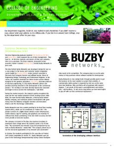
Built-In-Self Test (BIST) � Places the job of device testing inside the device itself � Generates its own stimulus and analyzes its own response
pattern generator
mux
circuit under test BIST Controller biston
to system
Response Analyzer
from system
good/fail
bistdone Introduction to VLSI Testing.27
Built-In-Self Test (BIST) (Cont.) • Two major tasks - Test pattern generation - Test result compaction
• Usually implemented by linear feedback shift register
F/F
F/F
F/F
Introduction to VLSI Testing.28
Random Number Generator (RNG)
F/F
•
F/F
•
F/F
•
F/F
•
0001 1000 0100 0010 1001 1100
0110 1011 0101 1010 1101 1110
1111 0111 0011 0001 (repeat)
1. Generate “pseudo” random patterns 2. Period is 2n - 1
Introduction to VLSI Testing.29
Signature Analyzer (SA) Input sequence 10101111 (8 bits)
G(x) =1+x2 +x4 +x5 +x6 +x7 Time 0 1 . . 5 6 7 8
Input stream 10101111 1010111 . . 101 10 1
+
1
2
+
3
4
+
5
P(x) = 1 + x2 + x4 + x5
Register contents 00000 10000 . . 01111 00010 00001 00101 Remainder R(x) = x2+x4
Output stream Initial state
1 01 101 Quotient 1+x2
Introduction to VLSI Testing.30
Z
Signature Analyzer (SA) (Cont.) P(x) : x5 + x4 + x2 + 1 2 Q( x) : x + 1
x7 + x6 + x 4 + x 2 + x5 + x 4 + x 2 + 1 = x7 + x6 + x5 + 1 7
6
5
4
2
P ( x)Q ( x) + R( x) = x + x + x + x + x +1 = G ( x)
Prob. of aliasing error = 1/2n where n is # of FFs Introduction to VLSI Testing.31
Memory BIST Architecture with a Compressor Before
After
di
addr
wen
Memory Module
data
sys_di data sys_addr sys_wen clk q hold_l Memory rst_l Module test_h si se
so
Introduction to VLSI Testing.32
rst_l clk hold_l test_h
di addr Memory wen
data
Module
compress_h clk rst si se
Compressor
sys_addr sys_d isys_wen
Algorithm-Based Pattern Generator
Memory BIST Architecture with a Compressor (Cont.)
q so
BIST Circuitry Introduction to VLSI Testing.33
sys_addr1 sys_addr2 sys_di2 sys_wen2 sys_addr3 sys_di3 sys_wen3 rst_ l clk
Algorithm-Based Pattern Generator
Three Memories and One Compressor
hold_l test_h
addr1 di2 addr2 wen2 di3 addr3 wen3
ROM4KX4 Module
4
data
RAM8KX8 Module
8
data
RAM8KX8 Module
data
8
compress_h BIST Circuitry se si
q Compressor
so
Introduction to VLSI Testing.34
Synthesis for Testability � Automatic v.s Semi-automatic � Commercial products - Testability analysis tools - Full / partial scan insertion - BIST insertion - Boundary scan insertion
� Research - RTL synthesis - FSM synthesis - Gate level synthesis - Boolean equation synthesis
Introduction to VLSI Testing.35
CPU Test Control Architecture Scan_i Scan path
Scan_o
Scan_en
logic rst_l clk hold_l
Bist
Memory
control
test_h compressor bist_so
bist_si
bist decoder scan decoder
MUX
bist_se
TDO
int_scan mbist decoder
TDI IR
TCK TMS
TAP Controller
Introduction to VLSI Testing.36
Testable Design Flow Prepare Initial Design RTL Code
Integrate all DFT Methodologies
Verify Functionality
Generate/Verify Test Patterns by FastScan
Identify Blocks for BIST/Scan
Insert/Verify Internal Scan Circuitry by DFTADvisor
Insert/Verify BIST Circuitry by MBISTArchitect
Synthesis to Gate Level
Modify/Verify Original Design
P/F
Reserve Dummy Ports for Internal Scan
Insert/Verify Boundary Scan Circuitry by BSDArchitect
Introduction to VLSI Testing.37
Problems re-thinking • A 32-bit adder --- ATPG • A 32-bit counter --- Design for testability + ATPG • A 1MB Cache memory --- BIST • A 107-transistor CPU --- All test techniques
Introduction to VLSI Testing.38
Conclusions Two major fields in testing • ATPG --- Fault simulation --- Test generation
• Testable design --- Design for testability --- Built-in self-test --- Synthesis for testability
Introduction to VLSI Testing.39