Introspection Mechanisms for Semi-Formal Verification in a System-Level Design Environment M. Metzger 1, F. Bastien 1, F. Rousseau 2, J. Vachon 1, and E. M. Aboulhamid 1 1 Université de Montréal, Canada. 2 Laboratoire TIMA, France 1 {metzgerm, bastienf, vachon, aboulham}@iro.umontreal.ca 2
[email protected]
Abstract A new generation of CAD tools is mandatory to cope with the growing complexity of System-On-Chip. We believe that they should be built on top of a modern and standard framework. ESys.NET is a design environment based on the .NET Framework. It takes advantage of advanced programming features which facilitates the integration of external tools. This paper presents a semi-formal verification tool for ESys.NET. Introspection ability is emphasized together with its capabilities to cooperate with third party tools. Introspection is used to retrieve the state of the model during simulation and to check a set of user defined rules. Neither the model nor the simulator is modified by the verification process. Experimentations on an AMBA bus model highlight the effectiveness of this approach.
1. Introduction The complexity of today’s electronic systems necessitates of a new EDA tools generation. High levels of abstraction and efficient verification techniques are the key features of modern design platforms. Although traditional hardware description language (e.g. VHDL and Verilog) are well suited to address hardware synthesis, their low-level of abstraction is often highly discouraging. SystemC [1] and SystemVerilog [2] constitute promising evolutions that provide higher level modeling and verification constructs taken from objectoriented programming and assertion-based verification. SystemC supports hardware/software co-design by extending C++ with system-level modeling constructs. However, C++ may not be the best for this task, mainly because of its lack of introspection capabilities [5]. Moreover, it is recommended [6] that modeling and simulation environments should be built inside larger standard software platforms like Java [3] or .NET [4]. Advanced programming features like introspection can greatly facilitate the development of such environments as well as their cooperation with external tools [5]. Introspection is the ability of a program to provide information about its own structure during runtime. Automated introspection is possible thanks to reflection mechanisms provided by programming environments [5].
ESys.NET [6][7] is an open-source system-level modeling and simulation environment based on the .NET framework which is standardized by ISO. It can be seen as an evolution of SystemC taking advantages of .NET capabilities. ESys.NET hence enables introspection, multi-lingual model definition, remote processing and refinement of models. This paper demonstrates how the conception of a verification tool is facilitated by ESys.NET’s architecture and its inherited .NET’s introspection capabilities. This tool uses a semi-formal approach based on observers. Observers watch the model during simulation and make sure that it conforms to the properties specified by the designer. It is important to mention that neither the model nor the simulator is modified by the verification process. In fact the source code of the system model is not needed to perform verification since introspection on a standard intermediate format retrieves all the required information. A similar tool built for SystemC would necessitate an additional layer to provide introspection [5]. The paper is organized as follows. Section 2 introduces the verification environment based on ESys.NET. Section 3 compares our approach to SystemC. Section 4 details the implementation of the verification process and tools. Section 5 presents the case-study and the performances analysis. Finally, Section 6 concludes this work.
2. ESys.NET verification flow 2.1. The .NET Framework and ESys.NET The .NET Framework is a modern environment created to ease the development and the deployment of distributed applications [4]. The core of .NET standardizes the development and execution of applications. It includes: x A Common Intermediate Language (CIL), which is an instruction set for a virtual machine. This enables interoperability across multiple programming languages (C#, VB.NET, managed C++ …) and portability. x Metadata definitions, which are additional information about the program embedded into the CIL code. Metadata includes description of types and attributes.
Proceedings of the Seventeenth IEEE International Workshop on Rapid System Prototyping (RSP'06) 0-7695-2580-6/06 $20.00 © 2006 IEEE
Description of types provides information about the structure of the application such as class hierarchy, interface implementation and members (methods, fields …). Attributes annotate the data structures also supported by .NET, including user defined attributes. Metadata can be consulted using the .NET’s reflection API. Built on top of the .NET Framework, ESys.NET is a system-level modeling and simulation environment which therefore benefits from the above facilities. Systems are modeled by a hierarchy of modules communicating via communication channels [6]. The behavior of a module is defined by processes. In terms of programming, ESys.NET is a class library. The following classes constitute the core of ESys.NET: x BaseModule. The base class of all user modules. It is also the base class of most of the model components (signals and channels). During model elaboration, all subcomponents of a module are registered by the simulator, using the .NET reflection mechanism. x BaseSignal. This is an abstract class that models the transmission of a single data on a bus. ESys.NET provides a set of specialized signals for common data types (integers, strings, characters, floating-point numbers…). Designers can implement signals for their own data types by extending BaseSignal. x Event. It is used to synchronize processes. For instance, BaseSignal owns a transaction event and a sensitive event. The first one is triggered each time a process writes the signal. The second one is only triggered when the new value is different from the previous one. To indicate that a particular method must be considered as a process by the simulator, the designer tags it with attributes. Attributes indicate the process’s type and the events it is sensitive to. Attributes can also be used by designers to request the execution of a method at given points in a simulation (e.g. beginning of simulation, end of a simulation cycle, etc). External tools can also be plugged in the simulator by registering callback methods. ESys.NET offers a set of hook-points where callbacks can be hooked. Using callbacks is one way to implement the observer paradigm. For instance, our verification tool requires to be notified at the end of each simulation cycle. It will thus hook itself to the simulator. This mechanism permits to extend the ESys.NET simulator without recompiling it.
2.2. Overview of the ESys.NET verification flow The verification layer we propose for Esys.Net is based on the observer paradigm. The state of the model under simulation is verified by the verification engine which observes the runtime evolution of the system and checks it against a set of formal properties: the observers. Figure 1 shows the links between simulation and
verification flows. Two simulation flows are pictured. The first one (A) is the actual ESys.NET simulation process. On the right side, a hypothetical simulation flow (C) based on SystemC is presented. The middle lane (B) describes our verification process. As illustrated, the simulation flow of Esys.Net (A) remains independent of the verification process (B). The properties to be verified are expressed using linear temporal logic (LTL) [13] (see Section 4.2). LTL formulae are stored in a text file apart from the model. Each formula is then transformed into an automaton (i.e. an observer) to be later executed in parallel with the simulation. An event of the system model, such as the rising edge of a clock signal, is used to synchronize the system model under simulation with observer automata. When the given event occurs, each observer automata executes transitions whose labels match the new current state of the model. If an automaton has no such transition, the execution fails and the property observed by this automaton is declared “invalid”.
2.3. ESys.NET simulation flow An ESys.NET system model can be written in any language supported by .NET such as C#, J#, managed C++, etc. Note that over 20 languages are supported. The model is compiled into CIL code by existing compilers. CIL code is used during the transformation of properties to perform syntax and type checking (operation 1a on Figure 1) to ensure, for example, that a specific signal exists in the model. Prior to simulation, the class describing the model is instantiated and elaborated by the ESys.NET environment. The resulting executable model is browsed (Figure 1 – 2a) to retrieve data that will be used during simulation to evaluate the state of the model. The callback methods registered within the ESys.NET simulator are called when the verification engine applies the observers on the simulated model (Figure 1 – 3a).
3. Comparison with SystemC 3.1. Adding reflection to SystemC Other frameworks such as SystemC are more difficult to interact with. The main drawback of SystemC is its lack of introspection. This is mainly due to the fact that SystemC is based on C++ which has limited introspection capabilities [5]. Additional libraries to support reflection are needed. In SystemCXML [9] Doxygen’s parser is used to extract an abstract system level description (ASLD) and to capture it in a XML file. The PINAPA project [10] adds a patch to the GNU C++ compiler and to SystemC. The compiler is used to get the abstract syntax tree (AST) of SystemC processes.
Proceedings of the Seventeenth IEEE International Workshop on Rapid System Prototyping (RSP'06) 0-7695-2580-6/06 $20.00 © 2006 IEEE
B
C
Verification Flow
SystemC Simulation Flow
Esys.NET System Model C# source
Properties Editor
SystemC Model C++ Source
Internal representation generation
A ESys.NET Simulation Flow
Compilation
Esys.NET System Model CIL code & metadata
Intro spec
1a tion
Transformation into automata
ll Ca 1b ods h t Me
C++ Compiler
Abstract Syntax Tree
SystemC Compiled Model
Instanciation And Elaboration
Binding phase
Model Instantiation And Elaboration
Execution Phase
C++ Parser Properties File
Link
2a Introspection
Executable System Model
3a Esys.NET Simulator
Callbacks
Observers Internal Representation
3b Methods Call
2b Binary
Executable System Model
Internal Representation
Meth ods Call 4b
Verification Engine
Modified SystemC Simulator & Verification Engine
SystemC Reflection Provider
Figure 1. The simulation and verifications flows
Internal SystemC structures resulting from the elaboration phase are exported to extract the structure of models. However SystemC core library allows basic introspection thanks to the get_child_objects method [1] which returns all sub-components of a given element in a design. However, this approach only permits to retrieve SystemC objects (modules, signals, clocks …), internal variables are thus still hidden. Beside this, the design of SystemC’s simulator makes it difficult to integrate external tools. The modification of the simulator source code is often the only solution [9]. Basic callbacks are available inside the design but are not usable from external libraries. The SystemC Verification (SCV) standard provides an API to develop test-benches at the transaction level [11]. It is black-box verification since the internal behavior of the system is not taken into consideration, contrary to the approach presented here. Nonetheless, introspection is used on input data to support arbitrary data types. The strategy exploits template mechanism to extend data type with introspection capabilities. The drawback is that one should describe manually user defined types.
3.2. SystemC verification Figure 1 (lanes B and C) presents a possible simulation/verification flow to emphasis the usefulness of introspection and hook-points. The technique used to add introspection to SystemC is inspired by the one proposed by PINAPA. The main drawback of this approach is the lack of introspection which prevents the binary form of a SystemC model to be exploited. Indeed a lot of
information is lost during the compilation process. The binary format resulting from the compilation highly depends on the compiler used and the architecture of the computer it targets. Developing a tool to directly explore the object file would be tedious. Thus, it is almost mandatory to use the source code files to get introspection information. This implies either to write a complete C++ parser or to use an existing one. The PINAPA project uses the C++ parser of gcc to build the abstract syntax tree (AST). It can be used to get information about the structure of the model (Figure 1 – 1b). After the instantiation and the elaboration of the model, the executable model and the AST need to be linked i.e. we need to link every entry in the AST (that can be introspected) to its actual instance. This is crucial to be able to recover the state of the model during simulation. To do so, one can use the information about binary structure of classes generated by the compiler (Figure 1 – 2b). The result of this process can be used to retrieve the state of the model for verification purpose (Figure 1 – 3b). Beside the additional introspection layer, the SystemC simulator needs to be modified to allow interaction with third party tools. The callbacks provided by SystemC 2.1 are virtual methods defined in system model components (modules, ports, channels…). Therefore, callbacks are accessible only from the model and not from an external environment. There are several solutions. One is to add an artificial module to export the callbacks. One could also add hook-points to the SystemC simulator, similar to the
Proceedings of the Seventeenth IEEE International Workshop on Rapid System Prototyping (RSP'06) 0-7695-2580-6/06 $20.00 © 2006 IEEE
4. Implementation of the verification Layer
variables are simply registered in the tree along with their type. Line 19 is the initial call of the method on the root of the model defined by class MyTopLevel. The tree construction is greatly facilitated by the use of reflection. It does not require the tedious implementation of a parser. Indeed the source file is not need at all. All the information is extracted from the compiled version of the model, no matter the language used, as long as it is supported by .NET.
4.1. Construction of the Design Structure Tree
4.2. Building observers
The structure of the model is needed for the construction of the observers. This information is available in the type structure that defines the model. It corresponds to the operation 1a of Figure 1. To avoid redundant introspection operations, we build a design structure tree that represents the modules hierarchy and contains the signals, the events and the observable variables of the model. This structure is quite similar to the ASLD of [9]. Compared to PINAPA, this can be seen as a higher level abstraction structure where only relevant information is kept. The pseudo-code below shows the basic structure of the exploration algorithm used to build the tree. Note that this pseudo-code is very close to the actual one.
Observers are built from linear temporal logic (LTL) formulae. LTL and Boolean logic are the base layers of Property Specification Language (PSL) [12]. Our tool can be seen as a first step to integrate a complete property specification language. LTL was originally designed to express complex requirements on infinite execution paths [13], [16]. But it can be used for semi-formal verification [8], [14]. LTL allows designers to formalize the temporal behavior of the model. It is composed of atomic properties, Boolean operators (and, or, not, imply) and temporal operators (Next, Always and Eventually). The semantic of temporal operators is: x The Next operator is noted X: X ij holds if ij holds in the next state. x The Always operator is noted []: [] ij holds if ij holds until the end of the simulation. x The Eventually operator is noted : ij holds if ij holds in some future state before the end of the simulation. x The Until operator is noted U: ij U ȥ holds if ij holds until ȥ holds. As an example, the following property specifies that a request must occur and be followed by an acknowledgement some time after:
ones found in ESys.NET. Finally the verification engine can be merged with the simulator (Figure 1 – 4b). As we can see, significant work is needed to provide introspection and extend SystemC. On the opposite, developing a verification tool with ESys.NET is facilitated since introspection and hook-points are parts of the core libraries.
01. object BuildTree(Type moduleType){ 02. foreach(FieldInfo f in 03. moduleType.GetFields()){ 04. if(f.FieldType == typeof(Event)) 05. AddEvent(f.FieldType) 06. else if(f.FieldType == typeof(Clock)) 07. AddClock(f.FieldName); 08. else if(f.FieldType==typeof(BaseSignal)) 09. AddSignal(f.FieldName,f.FieldType); 10. else if(f.FieldType==typeof(BaseModule)) 11. { 12. AddModule(f.FieldName); 13. BuildTree(f.FieldType); 14. }else{ 15. AddVariable(f.FieldName,f.FieldType); 16. } 17. } 18. } 19. BuildTree(typeof(MyTopLevel)); Figure 2. Design Structure Tree construction Using Introspection API
The core of the algorithm is a loop that iterates through all of the subcomponents of a module (line 2). A Type object contains the information offered by .NET about a specific type. The GetFields() method returns a collection of objects that describes all the instance variables of a given type. Depending on the type of the field, a node is added to the abstract tree. Event and Clock objects are simply added to the tree (lines 4 to 7). For signals, we must keep the type of the signal since it defines the data type carried by the signal. It will be used to perform type checking. If a field is a module extending the BaseModule, it is recursively explored (line 13). Other
(sig(req) == true && X sig(ack) == true) sig(req) == true and sig(ack) == true are atomic propositions. They are evaluated during simulation and reflect the state of the system model. The evaluation of a property is performed on its corresponding automaton. The automata corresponding to the formula given above is shown in Figure 3. true Init
sig(req) == true
true 1
true
sig(ack) == true
final
Figure 3. An example of automata
The construction of observers is divided in two parts, the transformation of LTL formulae into automata and the construction of atomic properties. The first one is achieved by the LTL2BA algorithm presented in [15]. The second one consists in building the labels of automata’s
Proceedings of the Seventeenth IEEE International Workshop on Rapid System Prototyping (RSP'06) 0-7695-2580-6/06 $20.00 © 2006 IEEE
transitions. These labels are comparisons between objects or with constant values like sig(req) == true. The first step is to build the two operands. We use the abstract tree presented in 4.1 to check that references to model objects are correct (e.g. the req signal exists) and to retrieve the type of objects. If the right operand is a constant the type must be resolved according to the type of the left operand. The obvious method to build an object from a string is to call a constructor with a string parameter, or to look for a static method Parse which takes a string argument and returns an object. When the two operands are built, the whole property can be constructed. Two checks are required. First the types of the two operands must be identical. Then one needs to make sure that the comparison operation can be performed, which means that the CompareTo or Equals methods are implemented. This mechanism allows to implicitly supporting all .NET primitive data-types (integers, Booleans, strings, floating point numbers …) as well as a wide range of other types (DateTime, IPAddress, Enumerated types …). Custom types can also be used in the verification process as long as the type complies with the construction of an object and the comparison methods as previously given.
4.3. Binding observers to the model While the observers are built, the model is instantiated and elaborated by the ESys.NET kernel. Atomic properties need to be connected to the elaborated model before the start of the simulation (see Figure 1 – 2a). For now, properties operands only contain paths to model objects but are not bound to an instance of the model. The current reference to the object is required to get the value of the operands and thus evaluate the property. Once again introspection is used; given a reference to an object and the name of one of its field, .NET offers a mechanism to obtain the value of the field. Since a reference to the toplevel and the path of the operands are available, a reference to the object pointed by the path can be obtained.
4.4. Binding observers to the simulator Each observer is synchronized by an event of the model. This defines the execution step of the automaton and a sampling of tested variables and signals. When the synchronization event occurs, properties of the executable transitions are evaluated and valid transitions are performed. The ESys.NET simulator offers a method to bind a procedure to any event of the model. To do so, a reference to the event object is needed. The method presented in 4.3 is used. Once a reference to the event is retrieved, a method is bound to it as follows:
simulator.BindMethod( new RunnableMethod(EventHandler), eventObject, methodID); where EventHandler is the name of the method to bind, eventObject is the event to bind to and methodID is a
unique string used to identify the link between the event and the method. When the synchronization event occurs the observer is flagged to be executed once the model will be stable. The state of the model during a simulation cycle is difficult to evaluate since it highly depends on the scheduling of processes. The ESys.NET simulator provides a cycleEnd hook-point triggered when the model is stable [6]. The following statement is used to bind a method to it: simulator.cycleEnd += new RunnableMethod(UpdateAutomata); The UpdateAutomata method will run all flagged
observers.
4.5. Evaluation of properties To perform a step in the automaton, the properties of all outgoing transitions from the current states are evaluated. This evaluation consists in retrieving values from the model and calling the Equals or CompareTo methods. It is important to mention that only a few introspection operations are done at this time in order to minimize the overhead.
4.6. Tools The verification layer is made of two separated applications: an advanced editor to specify properties and a simulation application. The editor provides advanced features such as syntax highlighting, auto-indentation and auto-completion. As the formalization of complex LTL properties can be difficult, a pattern instantiation mechanism was implemented to ease the specification of LTL properties. Presented in [17], patterns are a typical combination of properties that often occur in formal specifications. This reduces the risk of errors in the specification process. Moreover, the editor offers a graphical tree representation of the system model, using the information collected in the Design Structure Tree (Section 4.1). LTL properties are stored in a text file. This text file is read by the simulation application. This simulation application provides a graphical user interface to the ESys.NET simulation engine and to the verification engine. It displays the list of observers and their associated automata. A waveform viewer is also implemented to display the evolution of signal values during simulation.
5. Experimentation The verification layer implementation has been validated on a case-study describing an AMBA bus model. The case-study aims to validate the verification flow
Proceedings of the Seventeenth IEEE International Workshop on Rapid System Prototyping (RSP'06) 0-7695-2580-6/06 $20.00 © 2006 IEEE
proposed, find its limitations and show the usefulness of this type of verification. An evaluation of performances was also performed to identify bottlenecks in the verification engine. The properties to be checked come from a well known EDA company. They use these properties to validate their own AMBA bus model.
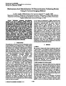
5.1. The AHB-Lite model Our case study is based on a specification from ARM [18] for the AMBA on-chip bus. The specification contains the description of a high performance bus called AHB. For this first experiment, a light version of this bus, called AHB-Lite [19], was considered: it only implements one master and doesn’t support split transactions. The model implements burst transfers, single clock edge operation and data width from 8 to 1024 bits. Additional features implemented by the full AHB bus concern the support of split transactions, the handover to the master in a single clock cycle and the support of up to 16 masters. It was optimized to decrease the simulation time. Decoder
The formula is made of two parts. The first one checks that the model is in a transfer phase. The htrans signal identifies the type of the frame currently transferred. It can be either not sequential or sequential, if the frame is the first of a burst sequence or not. The hwrite signal indicates that the master is writing data to a slave and the hready signal is the answer of the slave to signify it is ready to transfer. The second part of the formula (X (sig(hwdata) == "DATA") checks that a valid data is provided by the master. The two parts are connected by an implication operator. The always (“[]”) operator is put in front of the formula to ensure that it is valid during the whole simulation. The final specification file contains 23 main properties and 19 additional properties to evaluate the functional coverage of the simulation (e.g. each slave has been activated; all transaction types have been performed...). The specification file is loaded by the simulation application which initiates the transformation of each LTL formula into an automaton. Figure 5 shows the automata generated from the formula given above.
Slave #1
!p0 && !p1
select
!p3
init
Master
!p2
data out Slave #16
data in & response
select Read data / Response mux
addr & ctrl data in data out & response
Figure 4. High-level representation of an AHB-lite model
The model contains a master process, a decoder process and as many as 16 slave processes (Figure 4).
5.2. Verification process The system model was first debugged using classic in-code assertions and trace analysis. Thus, minor and obvious bugs were fixed. Then a set of properties written in English were formalized in LTL using the editor mentioned in Section 4.6. An example of a textual property and the corresponding LTL formula are given below. “In a write transfer, after the address phase of the transfer is sampled, the master should provide valid data in immediate next cycle”, is translated into: ltl_observer prop2(clk.event(posedge)){ [] (((sig(htrans) == "NSEQ" || sig(htrans) == "SEQ") && sig(hwrite) == true && sig(hready) == true) -> X (sig(hwdata) == "DATA")) }
final !p0 && !p1 && p4
data out & response
addr & ctrl
p4
!p2 && p4
addr & ctrl data in
true
!p3 && p4
Figure 5. Another example of automata
Labels p0, p1, p2, p3 and p4 respectively denote the following properties: sig(htrans) == "NSEQ", sig(htrans) == "SEQ", sig(hwrite) == true, sig(hready) == true and sig(hwdata) == "DATA". Just before the simulation, automata are bound to the model and to the simulator. After the simulation, the user is informed of the validity of each formula.
5.3. Performances Performances analysis was achieved on the AHB-Lite model with 16 slaves and a set of 42 observers. A profiler was used to record execution time and memory allocation. The overhead due to observers’ execution was evaluated during simulation. Approximately 67% of the simulation time was dedicated to observers. A simulation of 20 000 clock cycles took approximately 1.6 seconds without observers (250k events/sec). Adding observers raised the execution time to 5 seconds. At first sight, the simulation time rate used by observers can seem quite important. The situation can however be explained by the important number of observers compared to the fairly low complexity of the model. Indeed, the time overhead is directly proportional to the number of observers (to be more precise it is proportional to the number of atomic properties). The case study implied many observers (i.e. LTL formulae to check) verifying a fairly simple model.
Proceedings of the Seventeenth IEEE International Workshop on Rapid System Prototyping (RSP'06) 0-7695-2580-6/06 $20.00 © 2006 IEEE
Of course, verifying the same properties on a more complex model would lower the impact of the observers overhead. Furthermore the size of each formula tends not to exceed a certain size in practice. On the other hand, to evaluate advantages of doing introspection during the initialization phase (i.e. static introspection), the simulation was also performed using dynamic introspection (i.e. introspection during the evaluation of properties). In this case, the overhead rate due to introspection increased to 90%.
5.4. Discussions Concerning the model, the verification allowed us to find limit cases and synchronization bugs in our implementation. The hardest and longest part was not the construction of the observers but the construction of the model itself. Correction of bugs remains especially difficult. This case study was also a good opportunity to pinpoint weaknesses of the verification engine and find solutions to improve its performances. Among others, the formulation of complex behaviors with LTL is a difficulty frequently encountered in formal verification. However, the use of formula patterns [17] alleviates this task. Our LTL formula editor was thus extended to propose a set of such patterns to assist the designer. Furthermore, we are currently working on the implementation of another temporal logic to introduce a quantitative time specification. Moreover, the specification language lacks for complex operation like arithmetic or array access. A simple workaround can be used: instead of formalizing the complete property in the specification language, one can express more complex atomic properties in the model and use them in a complete LTL formula.
Parallelization of the verification engine and the simulation on different CPU (as well as on separate hosts) is also envisaged.
7. References [1] “SystemC, Version 2.1”, http://www.systemc.org/ [2] D.I. Rich, “The evolution of SystemVerilog”, IEEE Design & Test of Computers, Vol: 20 Issue: 4, Jul. 2003
[3] “Java Technology”, http://java.sun.com/, SUN [4] “.NET Framework”, http://www.microsoft.com/net, 2003 [5] F. Doucet, S. Shulka and R. Gupta, “Introspection in [6]
[7] [8]
[9]
[10] [11] [12] [13]
6. Conclusion and Future Work This paper presents a semi-formal verification method and tools in a system-level design environment. Our approach brought to light the steps of the verification process which could benefit from introspection and thus greatly simplify the development of modeling and simulation environments. Introspection is used to get the structure of the model and to retrieve data during simulation. ESys.NET can easily be extended thanks to hook-points to synchronize the execution of observers and the model simulation. Performances were evaluated on a concrete case-study. The overhead observed during simulation only depends on the number of observers. Performances should be improved by the next version of the .NET framework, especially by using generics classes for properties’ operands. Different execution models for temporal logics will also be explored which could also allow transaction level verification.
[14]
[15] [16] [17]
[18] [19]
System-Level Language Frameworks: Meta-level vs. Integrated” in DATE, 2003 J. Lapalme, E.M. Aboulhamid and G. Nicolescu, “A New Efficient EDA Tools Design Methodology”, ACM Transactions on Embedded Computing Systems, pp. 16, submitted February, 2005. Accepted July, 2005 http://esyssim.sourceforge.net D. Giannakopoulou, K. Havelund, “Automata-Based Verification of Temporal Properties on Running Programs”, In Annual International Conference on Automated Software Engineering, November 2001 Hiren D. Patel, Deepak A. Mathaikutty, David Berner and Sandeep K. Shukla, “SystemCXML: An Extensible SystemC Front End Using XML”, Formal Engineering Research using Methods, Abstractions and Transformations, Technical Report No: 2005-06. http://systemcxml.sourceforge.net/ M. Moy, F.Maraninchi and L. Maillet-Contoz, “PINAPA: The Extraction Tool for SystemC descriptions of Systemson-a-Chip”, in proceedings EMSOFT’05 C. Norris Ip and S. Swan, “A Tutorial Introduction on the New SystemC Verification Standard”, www.systemc.org Accellera Corp. PSL Language Reference Manual, http://www.eda.org/vfv/docs/psl_lrm-1.01.pdf, 2003 A. Pnueli, “The Temporal Logic of Programs”, In Proceedings of the 18 IEEE Symposium on Foundation of Computer Science, 1977 Eisner C., Fisman D., Havlicek J., Lustig Y., McIsaac A., et Van Campenhout D. “Reasoning With Temporal Logic on Truncated Paths”, in International Workshop on Computer Aided Verification, volume 2725 of Lectures Notes in Computer Science. Springer, 2003. P. Gastin, D. Oddoux. “Fast LTL to Büchi Automata Translation”, in conference on Computer Aided Verification, pp. 53-65, Jul. 2001 P. Wolper, M.Y. Vardi, and A.P. Sistla, “Reasoning about infinite computation paths”, IEEE Symposium on the Foundations of Computer Science, pp. 185-194, 1983 Matthew B. Dwyer, George S. Avrunin and James C. Corbett, “Property Specification Patterns for Finite-state Verification”, in the 2nd Workshop on Formal Methods in Software Practice, March. 1998. ARM company http://www.arm.com/ “AHB-Lite” http://www.arm.com/miscPDFs/1744.pdf
Proceedings of the Seventeenth IEEE International Workshop on Rapid System Prototyping (RSP'06) 0-7695-2580-6/06 $20.00 © 2006 IEEE