Journal of the Korean Physical Society, Vol. 55, No. 4, October 2009, pp. 1649∼1656
Inverse Verification of the Dose Distribution for Intensity Modulated Radiation Therapy Patient-specific Quality Assurance Using Dynamic MLC Log Files Jeong-Woo Lee Department of Biomedical Engineering, Research Institute of Biomedical Engineering, The Catholic University of Korea, Seoul 137-701 and Department of Radiation Oncology, Konkuk University Medical Center, Seoul 143-729
Jeong-Hoon Park, Jin-Beom Chung, Ji-Yeon Park, Bo-Young Choe and Tae-Suk Suh∗ Department of Biomedical Engineering, Research Institute of Biomedical Engineering, The Catholic University of Korea, Seoul 137-701
Doo-Hyun Lee Department of Radiation Oncology, National Cancer Center, Goyang 410-769 and Department of Biomedical Engineering, Research Institute of Biomedical Engineering, The Catholic University of Korea, Seoul 137-701
Semie Hong and Min-Young Kang Department of Radiation Oncology, Konkuk University Medical Center, Seoul 143-729
Kyoung-Sik Choi Department of Radiation Oncology, Sam Medical Center, Anyang 430-733 (Received 18 May 2009, in final form 9 July 2009) The aim of this study was to investigate a novel method for verification of the dose distribution for intensity modulated radiation therapy (IMRT) patient-specific quality assurance (QA) using dynamic multi-leaf collimator (DMLC) log files (Dynalog files). Dynalog files are recorded every 50 ms by using a MLC controller during the IMRT treatment. Dynalog files contain actual MLC positional information for various delivered dose fractions. As the nonuniform fluence is directly influenced by the MLC positional accuracy, our method for IMRT patient-specific QA can be performed using this information. Three nasopharyngeal cancer patients were selected for the evaluation. We developed an in-house program to convert MLC log files from an MLC controller to delivered MLC (dMLC) field files for the interface between the MLC controller and the treatment planning system. The in-house software, DMLC field file (DFF) converter, was written using programming language (Visual C++ 2005, Microsoft, Redmond, WA, USA). For inverse planning, Eclipse (v. 6.5, Varian, Palo Alto, USA) was used. The MLC log files were converted to dMLC files. The IMRT plans were recalculated and compared with the original plans. Comparisons were done via planar dose distributions using OP-IMRT software (v. 1.4, Wellhofer Dosimetrie, Germany) and dose volume histograms (DVHs) for targets and organs at risk (OARs). Gamma index (dose difference: 3%, distance to agreement: 3 mm) calculations were also performed for a quantitative analysis. There were significant differences (maximum dose difference: 587 cGy, maximum volume difference at 3000 cGy: 17%) in the DVHs of the parotid glands between planned MLC (pMLC)based and delivered MLC (dMLC)-based inverse IMRT QA (IVQA) plans for all three patients. The histograms showed an increased dose-volume in the dMLC-based IVQA deliveries compared to reference (Ref.) IMRT plans. Based on the present study, we can confirm the availability of our new approach to perform IMRT patient-specific QA providing a convenient and clear tool for IMRT dose verification. In the future, this method should be available for inverse on-treatment dose verification and for pre-treatment IMRT QA. PACS numbers: 87.53.Xd, 87.53.Tf Keywords: IMRT patient-specific QA, Dynamic MLC log file, DVH, Gamma index DOI: 10.3938/jkps.55.1649
-1649-
-1650-
Journal of the Korean Physical Society, Vol. 55, No. 4, October 2009
I. INTRODUCTION Intensity modulated radiotherapy (IMRT) beams are composed of complex multi-leaf collimator (MLC) segments. The non-uniform and customized fluence distribution in IMRT treatment is based on the interplay between an appropriate MLC performance and dose fraction in each segment. Investigators [1–5] have developed and presented a variety of IMRT quality assurance (QA) programs and have described their experiences in commissioning by using specialized solid phantoms and dedicated detectors. Although there are specialized radiographic and radiochromic films with 3D water-equivalent phantom systems and 2D detector array systems dedicated to IMRT QA, most are limited by their resolution, sensitivity, and application conditions [1]. Even though some general guidelines for IMRT QA have been issued by professional societies such as the American Association of Physicists in Medicine (AAPM) and the American Society for Therapeutic Radiology and Oncology (ASTRO), detailed procedures and criteria for quantitative analysis are not yet well established [3,4]. Nelms and Simon [6] conducted surveys on practical IMRT QA methods and criteria from at least 100 separate institutions in North America. The results showed that the measuring devices, performance methods, and quantitative analysis methods, including analysis tools and numeric criteria, were more or less different from one institution to the next, or had yet to be formally defined. Various quantitative analysis methods have also been suggested or modified based on reasonable decisions regarding IMRT QA results [7–11]. Low et al. [7] and Harms et al. [8] provided the mathematical formalism of gamma index tools for a quantitative evaluation of dose distribution. Although the gamma index evaluation to compare two dose distributions (one is planned and the other is delivered) is powerful in IMRT dose comparison, the clinical meaning of the pass-fail criteria (dose difference: 3%, distance to agreement: 3 mm) is not clear when it comes to the IMRT QA results. In plans for IMRT QA using specialized solid phantoms, so-called “hybrid plans”, anatomical and geometrical information on critical organs and targets is lost or is indiscernible in the dose matrix. Results from the planned and the measured dose distributions are difficult to analyze, and the correlations and potential discrepancies based on hybrid plans and phantom measurements are impossible to determine accurately. Some institutes have used DMLC log files to evaluate DMLC displacement errors during electronic DMLC compensation and dynamic treatments such as IMRT [12–15]. A Dynalog file is a record of the actual dose fractions versus the actual MLC leaf positions based on dynamic segmented treatment and is generated in the ASCII format [16]. Discrepancies between the planned ∗ E-mail:
[email protected]; Fax: +82-2-2030-5383
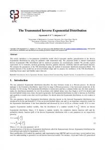
Fig. 1. The procedure of inverse dose verification for IMRT patient-specific QA. Quantitative analysis can be used for obtaining dose volume histograms of the “Volume of Interest” (VOI).
and the delivered DMLC files may lead non-uniform dose fluences different from the intended IMRT treatment. The aim of the present study is to suggest a new method for verification of the IMRT dose distribution by using DMLC Dynalog files and an in-house MLC field file converting program.
II. MATERIALS AND METHODS 1. Acquisition of MLC Log Files from Actual Dose Delivery
For this study, we used a Millennium 120-leaf MLC from a linear accelerator (CL21EX, Varian, Palo Alto, USA). The whole procedure is depicted in Fig. 1. Three nasopharyngeal cancer patients were selected for evaluation of our method for achieving IMRT patient-specific QA. An Eclipse (v. 6.5, Varian, Palo Alto, USA) was
Inverse Verification of the Dose Distribution for Intensity· · · – Jeong-Woo Lee et al.
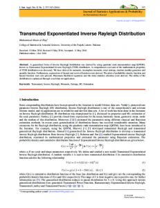
Fig. 2. The data structures of the (a) Dynalog and the (b) DMLC field files. The Dynalog file includes DMLC positional information every 50 ms. The DMLC field file contains the actual fluence data, which can be used for dose recalculation based on actual DMLC movement information in all segments. The dMLC files replace the pMLC files in comparison of the planned and the actual delivery.
-1651-
Fig. 4. In-house software, DMLC field file (DFF) converter, which converts Dynalog files to DMLC files. Dynalog files are composed of DMLC data from the A carriage and the B carriage. It is also possible to export fluence maps in ASCII format based on the Dynalog files.
Fig. 5. Comparison of IMRT plans calculated by using (a) pMLC and (b) dMLC. The dMLC field files were generated using Dynalog files from IMRT deliveries based on the original pMLC files. Fig. 3. An example of error analysis using the Dynalog File Viewer (DFV). (a) Dynamic leaf deviation histogram plots and (b) deviation values. (c) Dynamic leaf deviation root-mean-square (RMS) plots and (d) deviation values. The error histogram shows information for all leaf position deviations. The RMS error shows the calculated RMS values for leaf deviations. For further information, see the Reference Guide (DynaLog File Viewer).
used for inverse planning. MLC log files were recorded every 50 ms by using a MLC controller during the IMRT treatment [16]. Dynalog files contain actual MLC positional information for various delivered dose fractions. Dynalog and MLC field file examples are shown in Fig. 2. The Dynamic MLC positional error was analyzed using the Dynalog File Viewer (DFV) (Fig. 3). Basically, the Dynalog files were used for analyzing the root mean squares (RMS) MLC positional errors. Dynalog
file viewer (DFV) is a useful tool for this purpose. Error histograms are broken into 0.05 cm-bins spanning a total range of 0 − 1.00 cm [16].
2. DMLC Field File Converter for the Interface with the IMRT Planning System
We have developed an in-house program to convert MLC log files from an MLC controller to delivered MLC (dMLC) field files for the interface between the MLC controller and the treatment planning system. The inhouse software, DMLC field file (DFF) converter, was written using programming language (Visual C++ 2005, Microsoft, Redmond, WA, USA) (Fig. 4). Deliveries were performed based on the planning MLC (pMLC) field files in order to obtain the MLC log files. The MLC log files were converted to dMLC files by using the DFF
-1652-
Journal of the Korean Physical Society, Vol. 55, No. 4, October 2009
Fig. 6. An example of a hybrid phantom for IMRT patientspecific QA. (a) A hybrid plan using the nonuniform dose fluence obtained from the IMRT patient plan. (b) Setup for film measurement for comparison with the hybrid plan.
Fig. 7. Line profiles and γ-index comparisons using a DICOM-exported hybrid plan and film measurements.
converter. The converted DFFs were inversely imported and replaced with pMLC field files in the original IMRT plan. The recalculated DFF-based IMRT plan was compared with the original plan (Fig. 5).
3. Quantitative Analysis Based on Inverse Planning Using MLC Log Files
Comparisons were done via planar dose distributions by using the OP-IMRT software (v. 1.4, Wellhofer Dosimetrie, Germany) and dose volume histograms (DVH) for the targets and the organs at risk (OAR). The dicom files of the originally planned and the recalculated dose distributions were transported into the OP-IMRT software for analysis of the discrepancies due to DMLC misalignments. Gamma index (dose difference: 3%, distance to agreement: 3 mm) calculations were performed for a quantitative analysis. We applied the gamma index and DVH data to evaluate the impact of the discrepancy between the pMLC-based and dMLC-based IMRT 3D dose-volume data.
III. RESULTS As shown in Fig. 5, the dMLC-based IMRT plans were generated for nasopharyngeal cancer patients and were
Fig. 8. Differential dose volume histograms of gross tumor volumes (a, c, and e) and clinical target volumes (b, d, and f) from the pMLC-based reference (Ref) and dMLC-based inverse-QA (IVQA) IMRT plans for patient A, B, and C, respectively.
compared with the pMLC-based IMRT plans. Unlike the hybrid phantom IMRT QA method in Fig. 6 and Fig. 7, dose mapping on the anatomical and pathological images lets us easily and clearly understand the impact of discrepancies influenced by the misalignments of DMLC positions and segmental dose fractions during dynamic dose delivery. Table 1 and Table 2 show the planning summaries (targets and OARs) of the Ref. and the IVQA IMRT plans for patients A, B, and C. All patients had nasopharyngeal cancer. The prescribed doses were 70 Gy per 33 fractions at gross tumor volumes (GTVs) for three patients: 59.4 Gy for patients A and B and 63 Gy for patient C at clinical target volumes (CTVs) in the simultaneous integrated boost (SIB) technique. Regarding the number of fields applied in the IMRT plans, there were twelve, seven, and nine ports for patients A, B, and C, respectively. The DVH comparison revealed some discrepancies between the pMLC-based and the dMLC-based IMRT plans. There were significant differences (maximum dose difference: 587 cGy, maximum volume difference at 3000 cGy: 17%) in the DVHs of the parotid glands between the pMLC-based and the dMLC-based inverse IMRT QA (IVQA) plans for all three patients (Figs. 8, 9, and 10, and Table 2). For three different patients (A, B, and C), the disagreements between the Ref. IMRT plans and the inverse reconstructed QA plans (IVQA) were more severe
Inverse Verification of the Dose Distribution for Intensity· · · – Jeong-Woo Lee et al.
-1653-
Table 1. Reference planning summary (Targets) and IVQA IMRT plans for patients A, B, and C. All patients had nasopharyngeal cancer. Patients Plans No. of Total dose No. of Max. dose Min. dose Mean dose Standard deviation SIB‡ dose for CTV fields for GTV (cGy) fraction (cGy) (cGy) (cGy) (±cGy) (cGy) ¶ A Ref. 12 7000 33 7467 6145 6806 736 5940 IVQA† 7496 6157 6827 736 5940 B Ref. 7 7000 33 7574 6469 7169 166 5940 IVQA† 7615 6445 7204 157 5940 C Ref. 9 7000 35 7361 6499 6993 140 6300 IVQA† 7405 6535 7026 139 6300 Ref.¶ is an original IMRT reference plan. IVQA† is an inverse IMRT QA plan, which is generated by using inversely imported MLC field files based on the Dynalog files from the DMLC controller. SIB‡ stands for simultaneous integrated boost.
Table 2. Reference planning summary (OARs) and IVQA IMRT plans for patients A, B, and C. Patients
Plans Ref.¶
A IVQA†
Ref.¶ B IVQA†
Ref.¶ C IVQA†
OARs Brain stem Rt. parotid Lt. parotid Spinal cord Brain stem Rt. parotid Lt. parotid Spinal cord Brain stem Rt. parotid Lt. parotid Spinal cord Brain stem Rt. parotid Lt. parotid Spinal cord Brain stem Rt. parotid Lt. parotid Spinal cord Brain stem Rt. parotid Lt. parotid Spinal cord
Max. dose (cGy) 6053 3932 6076 4213 6225 4087 6401 4333 4662 6394 5478 4462 4637 6575 5781 4461 5010 5528 5789 4552 4969 6057 6376 4558
Min. dose (cGy) 2020 549 916 0 2026 550 954 0 1929 831 635 0 1929 876 663 0 223 1058 880 6.3 224 1078 890 2.4
Mean dose (cGy) 3150 1606 2261 1433 3197 1638 2435 1441 3046 2196 1679 1623 3037 2404 1862 1623 2105 2361 2430 1883 2103 2739 2821 1759
Standard deviation (± cGy) 630 685 968 1501 656 719 1099 1510 597 1109 853 1843 589 1246 1011 1841 1498 902 1033 1825 1493 1182 1307 1821
Ref.¶ is an original IMRT reference plan. IVQA† is an inverse IMRT QA plan, which is generated by using inversely imported MLC field files based on the Dynalog files from the DMLC controller.
around targets and both parotid glands (γ-index > 1.0), but were not severe around other structures, such as the brain stem or the spinal cord (γ-index 6 1.0) (Figs. 11,
12, and 13). There were some discrepancies between the Ref. and the IVQA plans on analysis of the γ-index distributions and planar dose distributions. Figs. 11, 12,
-1654-
Journal of the Korean Physical Society, Vol. 55, No. 4, October 2009
Fig. 9. Cumulative dose volume histograms of spinal cords (a, c, and e) and brain stems (b, d, and f) from the pMLCbased reference (Ref) and dMLC-based inverse-QA (IVQA) IMRT plans for patient A, B, and C, respectively.
Fig. 10. Cumulative dose volume histograms of right parotids (a, c, and e) and left parotids (b, d, and f) from the pMLC-based reference (Ref) and dMLC-based inverseQA (IVQA) IMRT plans for patient A, B, and C, respectively.
and 13 show that the failed area based on the γ-index criteria (dose difference: 3%, distance to agreement: 3 mm) was easily detected on the matched images.
IV. DISCUSSION AND CONCLUSION In this study, we investigated a novel methodology for performing inverse dose verification in the setting of IMRT patient-specific QA. This method could actually show delivered dose information on anatomical and pathological three-dimensional image sets instead of a solid phantom without critical volume data. Therefore, the method provided actual dose information on the volumes of interest to medical physicists and was much more helpful for evaluating the QA results. According to Nelms and Simon’s survey on planar IMRT QA analysis [6], many institutions use the singlegantry-angle composite method instead of field-by-field analysis. In addition, most institutions use a 3-mm of DTA and a 3% dose difference for the IMRT analysis on the survey. These parameters may not be acceptable as standard criteria for certain treatment sites [6]. In addition, it is very difficult to determine how dose discrepancies due to DMLC malfunction during dynamic segmented delivery impact the volumes of interest. If
Fig. 11. Comparison of the (a) Ref. plan with the (b) IVQA plan for patient A. An analysis was done by (c) transverse planar dose matching and (d) γ-index distribution (dose difference: 3%, dose to agreement: 3 mm).
the mismatched region is not a critical area or the effect is unimportant clinically, the QA results could be still acceptable, even though there is a large dose discrepancy above the QA criteria between the plan and the delivery. Contrary to the general IMRT QA using a hybrid plan, the inverse IMRT patient-specific QA method en-
Inverse Verification of the Dose Distribution for Intensity· · · – Jeong-Woo Lee et al.
-1655-
segments, so dose discrepancies were ultimately due to DMLC misalignments. Our study provides a convenient and reliable methodology to verify IMRT dose distributions. Based on the present study, we have confirmed the availability of our approach to perform IMRT patient-specific QA, thus providing a convenient and clear tool for quantitative analysis. In the future, this method could be available for inverse on-treatment dose verification, and for pretreatment IMRT QA.
ACKNOWLEDGMENTS Fig. 12. Comparison of the (a) Ref. plan with the (b) IVQA plan for patient A. An analysis was done by (c) coronal planar dose matching and (d) γ-index distribution (dose difference: 3%, dose to agreement: 3 mm).
This work was supported by Nuclear Research & Development Program of the Korea Science and Engineering Foundation (KOSEF) grant funded by the Korean government (MEST). (Grant code: 20090078119).
REFERENCES
Fig. 13. Comparison of the (a) Ref. plan with the (b) IVQA plan for patient A. An analysis was done by (c) sagittal planar dose matching and (d) γ-index distribution (dose difference: 3%, dose to agreement: 3 mm).
ables physicists and radiation oncologists more easily to evaluate the dose distributions delivered and the impact due to dose discrepancies. Recently, 2D ionization chambers or diodes arrays have become widespread in the application of IMRT patient-specific QA. Although 2D detector arrays are very useful in performing IMRT QA, they still have several limitations, such as anatomical and pathological information loss, limited measurement geometry, and relatively low resolution, compared to dosimetric films [17– 20]. In the present study, we proposed a new method for performing IMRT patient-specific QA by using automatic-generated Dynalog files quantitatively. The calculated DVH results showed that the regions requiring steep dose gradients (such as the parotids in nasopharyngeal IMRT planning cases) needed complex modulated
[1] A. L. Boyer, E. B. Butler, T. A. DiPetrillo, M. J. Enger, B. Fraass, W. Grant, C. C. Ling, D. A. Low, T. R. Mackie, R. Mohan, J. A. Purdy and M. Roach, Int. J. Radiation Oncology Biol. Phys. 51, 880 (2001). [2] T. LoSasso, C. S. Chui and C. C. Ling, Med. Phys. 28, 2209 (2001). [3] G. A. Ezzell, J. M. Galvin, D. A. Low, J. R. Palta, I. Rosen, M. B. Sharpe, P. Xia, Y. Xiao, L. Xing and C. X. Yu, Med. Phys. 30, 2089 (2003). [4] J. M. Galvin, G. Ezzell, A. Eisbrauch, C. X. Yu, B. Butler, Y. Xiao, I. Rosen, J. Rosenman, M. Sharpe, L. Xing, P. Xia and T. Lomax, Int. J. Radiation Oncology Biol. Phys. 58, 1616 (2004). [5] C. D. Venecia and P. Besa, J. Appl. Clin. Med. Phys. 5, 37 (2004). [6] B. E. Nelms and J. A. Simon, J. Appl. Clin. Med. Phys. 8, 76 (2007). [7] D. A. Low, W. B. Harms, S. Mutic and J. A. Purdy, Med. Phys. 25, 656 (1998). [8] W. B. Harms, D. A. Low, J. W. Wong and J. A. Purdy, Med. Phys. 25, 1830 (1998). [9] T. Depuydt, A. V. Esch and D. P. Huyskens, Radiother. Oncol. 62, 309 (2002). [10] N. L. Childress and I.I. Rosen, Int. J. Radiation Oncology Biol. Phys. 56, 1464 (2003). [11] L. Ma, N. Phaisangittisakul, C. X. Yu and M. Sarfaraz, Med. Phys. 30, 2082 (2003). [12] J. G. Li, J. F. Dempsey, L. Ding, C. Liu and J. R. Palta, Med. Phys. 30, 799 (2003). [13] A. M. Stell, J. G. Li, O. A. Zeidan and J. F. Dempsey, Med. Phys. 31, 1593 (2004). [14] W. Luo, J. Li, R. A. Price, L. Chen, J. Yang, J. Fan, Z. Chen, S. McNeeley, X. Xu and C. M. Ma, Med. Phys. 33, 2557 (2006). [15] L. Lee, Q. T. Le and L. Xing, Int. J. Radiation Oncology Biol. Phys. 70, 634 (2008). [16] Varian Medical Systems. DynaLog File Viewer reference guide, (Varian Medical System, Inc. 2003).
-1656-
Journal of the Korean Physical Society, Vol. 55, No. 4, October 2009
[17] B. Poppe, A. Blechschmidt, A. Djouguela, R. Kollhoff, A. Rubach, K. C. Willborn and D. Harder, Med. Phys. 33, 1005 (2006). [18] J. W. Lee, S. Hong, Y. L. Kim, K. S. Choi, J. B. Jung, D. H. Lee and T. S. Suh, Korean J. Med. Phys. 17, 131 (2006).
[19] A. V. Esch, C. Clermont, M. Devillers, M. Iori and D. P. Huyskens, Med. Phys. 34, 3825 (2007). [20] J. W. Lee, J. B. Chung, D. H. Lee, J. H. Park, B. Y. Choe, T. S. Suh, H. S. Jang, S. Hong, B. M. Park, M. Y. Kang, K. S. Choi and Y. H. Kim, J. Korean Phys. Soc. 53, 3436 (2008).