iPOS: A Fault-Tolerant and Adaptive Multi-Sensor Positioning Architecture with QoS Guarantees J¨urgen Bohn Institute for Pervasive Computing Distributed Systems Group ETH Zurich, Switzerland
[email protected]
Abstract. We describe the architecture of iPOS (short for iPAQ Positioning System), a fault-tolerant and adaptive self-positioning system with quality-of-service guarantees for resource-limited mobile devices. The architecture is based on a novel sensor modelling technique in combination with a probabilistic data-fusion engine, which is capable of efficiently combining the location information obtained from an arbitrary number of location sensors. As proof of concept, we present a prototypical implementation and discuss an experimental evaluation of the iPOS system. Keywords: Positioning, sensor modelling, sensor fusion, fault tolerance, quality of service, ubiquitous computing, mobile computing, location awareness.
1
Introduction
Location and position information is widely considered “the single most important piece of context” used in ubiquitous computing applications [ABO02], i.e., in applications that enable anytime, anywhere computing in everyday life situations [Wei93]. Consequently, localisation and positioning capabilities are of fundamental importance to mobile devices delivering such context-aware services and applications. The majority of existing indoor and outdoor systems for positioning and localisation rely on single or non-redundant combinations of location sensing technologies (cf. [HB01]). Therefore these systems are prone to service disruption and interferences, because the unavailability or failure of the single underlying technology leads to a complete failure of the service as a whole. In addition, many currently available location systems do not fully exploit the sources of location information that are readily available in existing everyday computing environments. Thus these location systems are not able to take advantage of various new sources of location information that are – as a side-effect – implicitly provided by the infrastructure. While technologies such as RFID, Wi-Fi, Bluetooth and ZigBee may have been invented with a certain primary application in mind (e.g., object identification or wireless data transfer), these technologies often leak location information during operation. Besides, the majority of existing location systems require the deployment of specialised hardware, such as grids of customised infrared or ultrasonic beacons, GPS receivers, which leads to additional costs. In addition, the number of small microcomputer-equipped objects and devices in everyday life environments is expected to increase significantly [HMNS01]. If these
devices have to be enabled to benefit from new positioning and location sensing techniques, it is particularly important to cope with the resource limitations and constraints these devices impose on potential positioning systems. A fundamental challenge of location and positioning systems is the quality of service of the services they provide, even more so in the case of mobile and resource-limited devices that do not feature costly equipment and highly reliable system components. For such resource-restricted mobile devices and computerised objects, computing resources found in the immediate locality provide a valuable source of localised redundancy that can be exploited for the realisation of dependable, fault-tolerant applications and services on the mobile devices themselves [Boh07b], thus freeing these devices from the dependence on centralised services and background computing and communication infrastructures. The Location Stack model proposed by Hightower et al. in [HBB02] is addressing some of these issues by means of a universal, multi-layered design abstraction for location-aware computing systems, providing a framework for the integration of arbitrary fusion techniques. Their implementation [GLHB03] is based on Bayesian filtering mechanisms for the data fusion layer, including Kalman- and particle filters [FHL+ 03]. While Kalman filters are computationally efficient, they require accurate sensors with comparably high update rates, which is not always the case with the kind of sensors we typically find in today’s ubiquitous computing environments. Besides, the complexity of particle filters reduces their suitability for the use with small, resource-limited mobile devices. In this context, however, integrating our fusion algorithm with a low overhead version of the Location Stack for explicit support of mobile devices could be an interesting option. The COMPASS location system [KB05] is a more recent positioning architecture that also takes up the idea of fusing different sensors with the help of a probabilistic fusion algorithm. However, so far no complete prototypical implementation and experimental evaluation is available.
2
Fault-Tolerant Self-Positioning Architecture
In the following, we present iPOS (short for iPAQ Positioning System), a robust and scalable probabilistic positioning system that addresses a number of shortcomings of common location systems for mobile devices (MoDs). The system is based on a lightweight map-based multi-sensor data-fusion architecture, which was explicitly tailored to operate efficiently and autonomously as a stand-alone service on small resourcelimited devices. The fusion architecture of our system is modularised and supports the integration of an arbitrary number of (internal) sensors and (external) third-party positioning services. Further, our positioning system is suited to work with standard off-the-shelf sensor hardware that is typically found in everyday life computing environments, thus allowing to exploit existing computing infrastructures for positioning. A special feature of our developed data-fusion architecture is the application of a novel event modelling technique that enables the positioning system to give quality-of-service (QoS) guarantees under certain conditions. As a proof-of-concept, we conclude with the description and experimental evaluation of a prototypical implementation of the iPOS system on a resource-limited handheld device. 2
2.1
Design Goals
The mobile positioning system architecture we developed and prototypically implemented realises the following design goals: – Fault Tolerance: The system is capable of tolerating the temporary or permanent failure of individual location sensing components (location sensors) by means of a redundant fusion architecture. – Adaptability: The fusion architecture is designed to perform an adaptive resource management, enabling the system to dynamically load or unload location sensing components during runtime, according to availability and coverage. – Self-Sufficiency: The positioning system is capable of self-sufficient local operation on a mobile device without the need of a background service infrastructure. – Extensibility: The modular design of our sensor fusion architecture makes it possible to easily integrate additional location sensors and location technologies. – Interoperability: By using a uniform internal representation of location information our systems enables the integration of arbitrary third-party positioning services. – Versatility: The positioning system is capable of integrating both geographic position information and symbolic location information, as well as processing local and global (WGS-84 [NIMA00]) position coordinates. – Quality-of-Service Guarantees: By discriminating “reliable” from “unreliable” location sensors in our model, the fusion engine is able to provide certain quality-ofservice (QoS) guarantees. – Support for Resource-Limited Mobile Devices: We provide a lightweight implementation of the architecture that performs well on resource-limited MoDs. 2.2
Architecture Overview
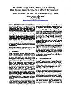
The positioning system we developed is executed on the MoD whose position is to be established during operation. The main architectural components of the positioning system are the resource manager, the fusion engine, the map handler, the internal event abstraction layer, and the sensor plugins (see Fig 1). In the context of our work, a sensor may be either a physical device or an application that in turn preprocesses the location information of other physical devices or applications. The sensor hardware or application can either be part of the MoD itself or constitute an external resource, such as a remote server, for instance. A sensor plugin is associated with one specific type of sensor. It preprocesses and transforms sensory location information into an abstract representation of position estimates we call sensor events. Each sensor event contains an absolute position with respect to a given twodimensional map model. New sensor events generated by sensor plugins are written into an internal sensor event queue for later retrieval and further processing. The core component of the system is the fusion engine, which processes sensor events to calculate the current position of the MoD. During each iteration of the positioning calculation, the fusion engine takes out the most recent sensor events from the sensor event queue and combines them by means of a map-assisted probabilistic sensor-fusion algorithm. The maps required in the process are obtained with the help of the map handler component, which can retrieve maps stored on the local file system or 3
Mobile Device Positioning System Resource Manager Sensor Plugins
Fusion Engine
Sensor Event Queue
Device 1
Position Event Queue
Position Event Server
Device 2 Maps
Map Handler
Map Files File System
Internal Clients
Initial Thread External Servers
External Servers
External Clients
Module Thread
Fig. 1. Overview of the architecture of the positioning system
download them from a remote server. The output of the fusion engine are time-stamped position events, which are stored in the position event queue. From that queue, the position event server takes out the most recent position estimates and makes them available to local or remote clients by means of a socket-based querying interface. The resource manager is responsible for managing the different components of the positioning service, including the initialisation, loading and unloading of components during runtime. In particular, the resource manager controls the operation of the sensor plugins, initialises the event queues and the map handler, starts the position event server, and controls the operation of the fusion engine. 2.3
Map Model
The map model we used in our system consists of a two-dimensional equidistant cell grid with square cells of equal size (e.g., cells of 0.5 m2 or 1.0 m2 ). Each cell within a grid is defined by an unambiguous cell index, and by a set of geographic position coordinates. The position coordinates may be local with regard to the map, or global according to the WGS-84 standard [NIMA00]. The specification of two global coordinates for two local reference positions in a map defines a coordinate transformation between local and global positions. 4
Each cell further contains a set of probability values for the transition to up to eight neighbouring cells, where each value can be set to zero for indicating obstacles or walls. A special type of cells called transition cells are used to connect a map to other maps. The map model further supports the placement of objects onto cells. An object has a unique symbolic identifier and a geographic position which is determined by the cell onto which the object is placed. It is possible to create arbitrary types of objects, each of which contains a number of specific attributes. For instance, an object of type “Radio Beacon” may represent a physical radio transmitter and contain attributes for its ID and its transmission range in meters, whereas an object of type “WLAN-RSS-Tuple” may represent a symbolic location identifier that is associated with a received signal strength (RSS) measurement of nearby Wireless LAN access points that was performed at the corresponding physical position, together with attributes describing the configuration of the measuring tool. The map model also provides a set of basic methods for processing maps, such as for joining and intersecting areas of a map, and for looking up and modifying cells or objects within a map. For facilitating map operations, the map model introduces a Region abstraction, which is defined as a set of cells, and the Clip abstraction, which is defined as the Region containing all cells that have an occupancy probability greater than zero concerning the current location of the MoD. The main idea of the Clip is to narrow down the number of significant cells that have to be considered during the mapassisted fusion process in order to enable an efficient position calculation on resourcelimited mobile devices. 2.4
Sensor Event Model
Sensor plugins generate sensor events. We say that a sensor event fired when it was created by a sensor plugin. For each type of sensor, a separate class of sensor events is defined that share common global properties. A sensor event contains location information in the form of either a symbolic location identifier or a geographic position. A sensor event containing symbolic location information we refer to as symbolic sensor event. Likewise, a sensor event containing geographic position information we call a geographic sensor event. The location information provided with a sensor event defines the (geographic) centre point of that sensor event. For sensor events featuring a symbolic location, the corresponding centre point is determined with help of the map model described earlier. For that, each class of symbolic sensor events is assigned a separate class of objects in the map model. Then each symbolic sensor event of that class is linked to an object of the corresponding object class with the same individual symbolic identifier. Any such object has to be added to the respective grid map during the learning or initialisation phase of the positioning system. Obviously, the mapping of sensor events to objects in the map model is bijective. Therefore, with the help of the map model, it is possible to decide a priori which symbolic sensor events can possibly occur within the mapped area. In particular, it is also possible to determine the symbolic sensor events that did not fire (i.e., where not created by sensor plugins) during an iteration of the sensor event fusion process. We exploit this ability to increase the accuracy of our position calculation in the sensor fusion engine. 5
Concerning shared properties, each class of sensor events contains a range property. Together with the individual centre point, the range defines the spatial area of influence of a single sensor event in the two-dimensional map model, which corresponds to a Region in the map model. Thus the range of a sensor event class is a measure of the accuracy of the corresponding sensor plugin and its provided location information. In the following, whenever we speak of the intersection or union of sensor events, we refer to the intersection or union of the respective Regions spanned by these sensor events. We also say that a sensor event covers an individual cell if that cell is part of the Region of the sensor event. Each sensor event class further contains a property blocking indicating whether the area of influence of the sensor event is affected by obstacles or walls. For instance, a sensor plugin for sensing nearby radio beacons may create a sensor event containing the symbolic identifier of a detected beacon as symbolic location identifier. Then, by means of the map model in which a corresponding beacon object was placed earlier and named accordingly, the geographic position of the cell containing the beacon object is taken as the geographic position of the radio beacon. Alternatively, in case the detected beacon already transmits its physical position, no further map lookup is required to establish the centre point of the corresponding sensor event. For instance, given a maximum range of 10 m for the type of radio beacon, the area of influence of the sensor event during the map-based fusion process is determined by identifying all cells within that range, starting from the centre point. In the process, if the sensor event is blocking, only cells that are in line of sight from the centre point are considered. 2.5
Las-Vegas and Monte-Carlo Sensor Events
Depending on the type of sensor, position estimates vary in terms of accuracy and reliability. In our system, we discern two categories of sensor plugins: (1) unreliable sensor plugins, which we call Monte-Carlo sensor plugins, and (2) reliable sensor plugins, which we call Las-Vegas sensor plugins. Likewise, we refer to a sensor event generated by a Monte-Carlo or Las-Vegas plugin as Monte-Carlo or Las-Vegas sensor event, respectively. The semantics of the Las-Vegas and Monte-Carlo sensor plugins follow the semantics of the behaviour of randomised algorithms. A Monte-Carlo sensor plugin (in short: MC-plugin) shows a deterministic behaviour in so far that it always returns a result upon request, in our case location information encapsulated in a Monte-Carlo sensor event (in short: MC-event), but the resulting position information is liable to be erroneous and possibly false. In contrast, a Las-Vegas sensor plugin (in short: LV-plugin) displays the following indeterministic behaviour: it does not always return a Las-Vegas sensor event (in short: LV-event), but if it does, the provided location information is correct in the following sense: it is guaranteed that the actual current position of the MoD lies within the boundaries determined by the known accuracy and area of influence of the respective Las Vegas sensor event. A typical class of LV-plugins are plugins that detect the presence of radio beacons for which the maximum range (i.e., the maximum distance from which a beacon can still be detected) can be safely and accurately determined. Consequently, if a beacon of that type is detected, the current position of the MoD is known to be within the area of influence of the beacon (i.e., within the physical area in which the beacon can be 6
detected). The knowledge of the maximum range yields an upper bound for the positioning error (which equals the maximum distance between any two physical positions within the range of the beacon). The upper bound for the positioning error can be interpreted as an upper bound for the accuracy value of the sensor (a higher metric accuracy value actually means a lower accuracy). An important quality of LV-plugins is that if multiple beacons (which may belong to different classes and therefore feature different ranges) are detected by the corresponding LV-plugins, then the current position of the receiver (i.e., the MoD) by definition has to lie in the intersection of the individual areas of influence of the involved beacons. In the map model, this results in a Region that is equal to or smaller than the Region covered by the beacon with the smallest range. This implies that the resulting accuracy for the intersection of multiple beacons is higher (i.e., better) or equal to the one of the beacon with the highest accuracy (and with the lowest accuracy value). A further implication of the reception of multiple LV-events is that the current Clip (i.e., the Region containing all cells that are candidates for the current position of the MoD, see Sect. 2.3) can be narrowed down to the intersection of the Regions of all received LV-events. Typical examples for MC-plugins are plugins that rely on received signal strength (RSS) measurements of all detected senders in the vicinity of the MoD, and which determine the best match out of previously empirically learnt RSS patterns for a number of reference positions by means of a nearest neighbour metric, for instance. Obviously, in case the signal strength values for some of the senders vary significantly (e.g., due to interference or mobile obstacles temporarily blocking or reflecting the signals), the calculated best match possibly yields a reference position that is far off the true best match for the actual current position of the mobile device. 2.6
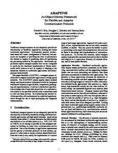
Operation of the Probabilistic Fusion Engine
The probabilistic fusion engine plays a pivotal role in our positioning system. Running on top of a two-dimensional map model, the fusion engine during each iteration step takes the sensor events stored in the sensor event queues, fuses their location information, and stores the resulting position events in the position event queue. Finally, based on a mobility heuristic that respects previously known positions, the new most likely position of the MoD is determined based on the computed occupancy probabilities of the cells in the Clip. A high-level schematic of the flow of control and operation of the probabilistic fusion engine and the integration of the different parts of the fusion engine is shown in Fig. 2. For a detailed formal description of the probabilistic fusion algorithm, see [Boh07b]. As we can see in Fig. 2, the fusion engine performs position calculations in iterations, each of which begins with the intention of sensor events from the sensor plugins. Based on these sensor events, the engine computes the Clip containing the cells with an occupancy probability greater than zero concerning the current location of the MoD. Then the fusion engine extracts position information from the available LV- and MCevents and merges them with the existing position probabilities (cell occupancy probabilities) that were calculated and stored in the respective cells of the map model during the previous iteration. By fusing the occupancy probabilities of previous iterations with 7
INITIALIZATION Read LV- and MCevents from sensor event queues.
# LV-events >0
# MC-events >0
NO
NO YES
YES
Clip := Intersection of the Regions of all LVevents
Clip := Union of the Regions of all MCevents
LV-event processing: Update cell occupancy probabilities for all cells in Clip using available LV-events.
MC-event processing: Update cell occupancy probabilities for all cells in Clip using available MC-events.
# MC-events >0
YES
Absence of sensor events: Update Clip and cell occupancy probabilities in the grid model by applying the mobility heuristic.
Clip normalization: Normalize cell occupancy probabilities in Clip.
NO
Position derivation: Estimate position using the maximumlikelihood heuristic.
NEXT ITERATION
Write new position event into position event queue.
Fig. 2. Control loop of the probabilistic map-based fusion engine
the newly obtained location information, a continuity of the positioning is achieved, assuming that subsequent positions of the MoD are spatially proximate. Further, it enables the system to provide position estimates even in case no sensor events are available. Based on the fundamental properties of our Las-Vegas and Monte-Carlo sensor modelling technique, the calculation of the Clip can be performed in an efficient manner as the intersection of all LV-events that fired during an iteration. Further, the knowledge of the absence of an LV-event with regard to cells in the Clip that are covered by a LVplugin in the map model is used for implementing a negative feedback by penalising the affected cells with a lower occupancy probability (Fig. 3-C). In the absence of LV-events, due to the inherent inaccuracy of MC-events, the Regions of any detected MC-events are joined with the current Clip to obtain the new Clip. However, if reliable LV-events were obtained, MC-events do not affect the size of the 8
-1 nt ve -E LV CLIP
-1 nt ve -E LV
-1 nt ve -E LV
-1 nt ve -E LV
CLIP
CLIP
-2 nt ve -E V L
A
-3 nt ve -E LV
LV
CLIP
t-2 en Ev
LV
C
B
-3 nt ve -E LV -1 nt ve -E C M
t-2 en Ev
D
Fig. 3. Exemplary Clip calculation in the grid map model based on two LV-events and on one MCevent. LV-events #1 (A) and #2 (B) fired and their intersections define the cells of the Clip. Since the reliable LV-event #3 did not fire (C), its cells have position probability zero and therefore are removed from the Clip. MC-event #1 does not affect the size of the clip, but only influences the cell occupancy probabilities of the cells it occupies within the Clip (D). A darker shade corresponds to a higher cell occupancy probability of the MoD
Clip, but instead only provide the fusion engine with additional position information for the cells in the clip they cover (see Fig. 3-D).
3
iPOS Positioning System Prototype
We prototypically implemented a fully functional prototype of the positioning system according to the system architecture presented in Sect. 2, which we called (iPAQ POsitioning System, or in short iPOS. The term iPAQ refers to the fact that the MoD was represented by a handheld device of type HP iPAQ (H5450 Series, PocketPC 2002). In our system, we employed the following location sensing technologies (see also Fig. 4): (1) active RFID beacons (i-Q8 tags and i-Card3 PCMCIA RFID reader by Identec Solutions), (2) Bluetooth-enabled sensor nodes (BTnodes, www.btnode.ethz. ch), (3) densely distributed passive RFID tags as part of the SDRI Positioning prototype [Boh07a], (4) a “smart badge” in combination with two “RFID gates”. The two RFID gates each consisted of one RFID antenna (Softronica ANTMR5000) connected to one RFID reader device (RIDEL5000-I, 13.56 MHz). Each reader device was controlled by an RFID-gate application running on a notebook computer. The MoD was equipped with a passive RFID tag (Philips I·CODE Type 1 [Phi06]) serving as a “smart badge”. Whenever the RFID-gate application detected the presence of the badge, it created a time-stamped RFID-gate-event containing the symbolic location identifier (or alternatively the geographic location) of the RFID gate and the ID of the detected tag. The RFID-gate-event was then forwarded to a tuple space managed by a centralised server that provided a socket-based communication interface. The RFID Gate LV-plugin on the MoD connected to this interface in order to retrieve the RFID-gate-events for its given tag ID (badge ID). The handheld device itself was directly connected to a BTnode which it employed for discovering nearby BTnodes in the environment. Figure 5 shows the MoD hardware setup. Further, for the interaction with the densely distributed RFID-tag infrastructure, we used the SDRI Positioning System as a reference positioning service. The iPOS positioning software on the handheld wirelessly connected to the SDRI positioning 9
Active RFID Tag
SDRI Positioning Trolley
BTnode (Bluetooth-enabled)
SDRI Infrastructure Fig. 4. Location sensing technologies: active RFID tags, active Bluetooth enabled sensor nodes (BTnodes), and SDRI Positioning System [Boh07a] with densely distributed RFID tags (superdistributed RFID tag infrastructure (SDRI) prototype [BM04])
service, which was executed on a separate notebook computer mounted on the trolley of the SDRI Positioning System (see Fig. 4). The iPOS software was implemented in Java using the CrE-Me 4.0 Java Virtual Machine by NSICOM. 3.1
Implemented Sensor Plugins
We implemented the sensor plugin components as independent, active modules that are managed by the resource manager component. In the following, we list the sensor plugins we developed and implemented based on the available sensing technologies. An overview of the sensor plugins and their configurations is shown in Table 1. The Active RFID LV-Plugin treats active RFID tags as individual radio beacons. For every detected active RFID tag, the plugin creates an LV-event containing the ID of the tag as symbolic location identifier. Consequently, each such beacon has to be inserted as an object into the map model at the cell that corresponds to the physical location of the beacon, to enable the fusion engine to resolve the geographic positions of the sensor events during the fusion process. The range of the plugin depends on the transmission power of the tags and on the sensitivity of the reader, both of which were configurable in our case. We used a configuration that limited the transmission range of the active RFID tags to below 3 m, resulting in a positioning accuracy per beacon that was better 10
HP iPAQ H5450
Identec i-Card3
BTnode
Serial Cable
Fig. 5. Mobile iPOS client with i-Card3 PCMCIA reader and BTnode connected by serial cable Table 1. Overview of implemented sensor plugins. The entries marked with an asterisk depend on the characteristics of the used sensor hardware or third-party positioning service, respectively Sensor Active RFID Beacons Bluetooth Beacons SDRI Prototype RFID Gate Generic LV-Plugin Active RFID RSS [2-m-grid] Bluetooth RSS [2-m-grid] WLAN RSS Generic MC-Plugin
Type Range/Accuracy Blocking LV ±3 m yes LV ±30 m yes LV ±0.3 m yes LV ±0.5 m yes LV * * MC ±5 m yes MC ±5 m yes MC ±10 m no MC * *
than ±3 m. The radio signals of the active RFID tags we used were blocked by walls. Therefore the sensor events were configured as blocking. The basic functionality of the Bluetooth-based LV-Plugin is similar to the one of the active RFID-based LV-plugin: each Bluetooth sender (here: BTnode) is treated as a radio beacon and its Bluetooth MAC address used as symbolic location identifier. A reliable upper bound of the transmission range of the BTnodes was experimentally evaluated to 30 m and set accordingly in the corresponding sensor event class. As a result, the accuracy of ±30 m of the Bluetooth beacons was much lower than the one of the active RFID beacons. The SDRI Positioning LV-Plugin makes use of an existing RFID-based self-positioning system we developed at ETH Zurich (SDRI Positioning System [Boh07a]) that directly provides location information in the form of geographic position coordinates at a rate of approx. 1 Hz. The SDRI Positioning LV-Plugin connected to the RFIDbased positioning service via a wireless network connection and created an LV-event for each obtained position. Further, based on the given hardware configuration and tag 11
distribution density of the prototypical SDRI, the range of the LV-plugin was set to 0.15 m, and the sensor events were configured as blocking. The RFID Gate LV-Plugin is the only plugin we implemented that makes use of a background service infrastructure: the LV-plugin has to connect to a central server and ask for any recent RFID-gate-event that contains the user’s RFID badge ID as identifier. For our experiments, we placed the RFID gates such that they covered the area of a single cell of 1 m2 in the map model, which corresponds to a range of approx. 0.5 m of the respective sensor events. Since RFID tags cannot be detected through walls, the sensor events were configured as blocking. As a basis for the MC-plugins we implemented an Abstract MC-plugin based on received signal strength (RSS) measurements of radio signals. The plugin first measures the signal strength values of all radio transmitters that are received at the current physical location and then compares the obtained RSS values with previously stored reference values (positions). With the help of a least-squares-metric, the known reference position whose RSS vector exhibits the minimum error compared to the current RSS vector is chosen as the current position of the MoD. Obviously, the quality of the positioning depends on the quality of the reference positions. In particular, if no reference position close to the true position of the MoD is available, or if the RSS measurements are distorted, the calculated position is liable to be wrong or far off the mark. Therefore, this type of plugin is considered unreliable. Based on the Abstract RSS MC-Plugin we created the Active RFID RSS and Bluetooth RSS plugins. In order to receive multiple senders per measurement, we used a configuration with a grid-like distribution with 2 m distance between adjacent units in the test area (see Fig. 6), which resulted in a range of up to 5 m for the corresponding plugins. The radio signals of our active tags and Bluetooth beacons were blocked by walls. For this reason, the sensor events were configured as blocking. Since we were not able to access the signal strength values of the Wireless LAN interface on our iPAQ handheld device, we couldn’t complete the implementation of the WLAN RSS plugin. We further developed generic plugins, the Generic LV-Plugin and the Generic MCPlugin, which enable the straightforward integration of arbitrary third-party positioning services that exhibit Las-Vegas or Monte-Carlo characteristics into the iPOS system.
4
Experimental Evaluation
In preparation of our practical experiments, we deployed our hardware for the sensing infrastructure in the corridor of our office building at ETH Zurich. We also created a grid map model of the corridor with square cells of 1 m2 size, which resulted in a precision of 1 m2 for the iPOS position estimates and in an inherent average position error of 0.35 m, given that the iPOS system returns the coordinates of the centre point of the cell in which the MoD is thought to be located. The BTnodes serving as Bluetooth senders and the active RFID tags were distributed in a grid with 2 m distance between adjacent entities, with a displacement of 1 m between the two grids. The map model was updated by inserting BTnode- and active-RFID-objects into the map at the respective positions as shown in Fig. 6. An area of the corridor was also covered with densely distributed RFID tags (see area shaded 12
in grey in the figure), using four RFID-tagged foil templates. In the figure, we can also see the locations of the map objects placed for the two RFID gates (i.e., the areas covered by their antenna fields), marked with grey rhombuses (diamonds) in the grid map model. The map objects for the reference positions that were learnt for the Bluetooth RSS MC-Plugin are marked with small squares in the map model. We further laid out a test track of 38 m, which started in a side hall and led in a loop through the prepared corridor as displayed in Fig. 6.
Fig. 6. Excerpt of the grid map model showing the experimental setup and test track
Our experimental method was as follows: The handheld running the iPOS application was put on top of the trolley that also carried the SDRI Positioning System. One person pushed the trolley along the test track marked in Fig. 6, while a second person initiated positioning samples at well-defined locations using a developed sampling tool. We executed our measurements based on two different ways of traversing the test track: (A) stop-and-go mode where the person pushing the trolley advanced one meter (i.e., one cell in the model) every five seconds, and at each position we took a position measurement using a sampling tool we developed, and (B) continuous mode where the person pushing the trolley advanced at a constant speed of 0.4 m/s while a second person took position samples after every two meters of distance the trolley had covered. We performed six positioning experiments based on different combinations of sensor plugins. An overview of the experimental configurations and the obtained positioning results is displayed in Table 2. For the experiments in stop-and-go mode (mode A), we performed five test runs per configuration, collecting 39 samples per run, which resulted in an overall number of 195 samples. For the experiments in continuous mode (mode B), five test runs were performed and 20 samples were collected during each run, yielding a total of 100 samples per configuration. The SDRI Positioning LV-plugin and the RFID Gate LV-plugin were modelled with the accuracy of one cell each. The Active RFID LV-Plugin was modelled with an accuracy of five meters. 13
Table 2. Overview of experiments based on different combinations of sensor plugins. For each experiment, n describes the number of collected samples, α the average error in meters, and σ the standard deviation of the error in meters Exp. Config. Active Plugins Mode #Runs n α [m] σ [m] 1 1 Active RFID LV RFID Gate LV SDRI Pos. LV A 5 195 1.14 0.97 2 1 Active RFID LV RFID Gate LV SDRI Pos. LV B 5 100 1.64 1.14 3 2 Active RFID LV A 5 195 1.44 1.01 4 2 Active RFID LV B 5 100 3.03 2.80 5 3 Active RFID LV RFID Gate LV SDRI Pos. LV Bluetooth RSS MC A 5 195 1.25 1.25 6 4 Bluetooth RSS MC A 1 39 6.66 3.62
5
Experimental Results
By comparing experiments number 1 and 2 based on the same configuration of LVplugins (see Figures 7 and 8), we can see that the accuracy of the iPOS positioning service in the stop-and-go mode was 30% higher compared to the continuous mode. With regard to the map model, the accuracy of 1.14 m with a standard deviation of about 1 m for the stop-and-go mode can be interpreted as follows: the average error amounts to approx. one cell in horizontal or vertical direction, with a standard deviation of one cell. Likewise, the error for the continuous mode in experiment no. 2 can be interpreted as amounting to approx. one cell in diagonal direction of the correct cell in the grid, with a standard deviation of approx. one cell. We consider this accuracy a good result in comparison to the achievable precision of the measurements. We found that the main reason for the decline in accuracy with increased mobility was the short delay between the creation of the sensor event and the processing in the fusion engine, which in particular affected the location information obtained via wireless connection from the SDRI Positioning LV-plugin and from the RFID Gate LVplugin. We can see in Figures 7 and 8 that the average error approximately doubles at those places along the path where the SDRI Positioning and RFID Gate plugins were encountered by the MoD. This observation also holds true for the results obtained using only the Active RFID LV-plugin for positioning: the average error of the continuous experiment (no. 4) increased by approx. 110% in comparison to the stop-and-go experiment (no. 3), with an even higher increase of the standard deviation. The stop-and-go experiment based on the active RFID tags modelled as a reliable LV-plugin further showed that the average and maximum accuracy of the majority of position estimates calculated by the iPOS fusion engine were contained in the range of the corresponding LV-plugin. Comparing the performance of the Active RFID LVplugin in experiments no. 3 and 4 with the overall performance of the multi-plugin 14
15 14 13 12 11
Error [m]
10 9 8 7
AVG MIN
6
MAX
5 4 3 2 1 0 0 1
2
3
4
5
6
7
8
9 10 11 12 13 14 15 16 17 18 19 20 21 22 23 24 25 26 27 28 29 30 31 32 33 34 35 36 37 38
Path [m] RFID Gate
SDRI
RFID Gate
SDRI
15 14 Positioning errors for experiment no. 1, configuration no. 1, mode A. Plugins: Active Fig. 7. RFID13LV-plugin, RFID Gate LV-plugin, and SDRI Positioning LV-plugin (runs = 5, n = 195, α = 12 1.14 m, σ = 0.97 m) 11
Error [m]
10 9 8 AVG MIN MAX
7 6 5 4 3 2 1 0 0
2
4
6
8
RFID Gate
10
12
14 16
18
20
22 24
26
28 30
32
34
36 38
Path [m] SDRI
RFID Gate
SDRI
Fig. 8. Positioning errors for experiment no. 2, configuration no. 1, mode B. Plugins: Active RFID LV-plugin, Bluetooth LV-plugin, RFID Gate LV-plugin, and SDRI Positioning LV-plugin (runs = 5, n = 100, α = 1.64 m, σ = 1.14 m)
experiments no. 1 and 2, we can see that the accuracy of the fusion process is indeed determined by the accuracy of the most accurate active LV-plugin at a time. In our case, this concerned the stretches along the test track where the areas of influence of the RFID Gate LV-plugin and of the SDRI Positioning LV-plugin were entered by the MoD. Finally, we performed an experiment where we added the Bluetooth RSS Plugin to the plugins of configuration 1 Here we can see that the overall accuracy has slightly decreased in the average case, with a few outliers with regard to the maximum positioning error. The reason for this effect was that the Bluetooth RSS MC-plugin on its own proved to be very unreliable and inaccurate, which had a pronounced negative effect whenever only MC-events and no LV-events were detected, as the Clip was then recal15
culated based on the potentially very inaccurate MC-events (see experiment no. 6). In the experiment based on LV-plugins only, the Clip was only extended according to the mobility heuristic and not changed completely in the absence of LV-events. To address this issue, we changed the Clip calculation procedure in the case that only MC-events are obtained to joining the existing Clip with the Regions of the MC-events rather than replacing the Clip with the union of the Regions of the MC-events. The Active RFID LV-Plugin and Active RFID RSS MC-Plugin could not be employed in parallel on the MoD as both plugins made use of the same RFID hardware and required incompatible driver settings. For a complete account of the performed experiments and an in-depth evaluation and discussion of the results refer to [Boh07b]. 5.1
Discussion
In the following, we discuss our experimental results according to the taxonomy for assessing location technology proposed by Hightower [HB01], which considers scalability, cost, recognition and limitations. Scalability. A major advantage of the iPOS positioning system is its extensibility as a result of its open plugin architecture and the support of global positioning coordinates according to the WGS-84 standard [NIMA00]. This makes it possible to integrate arbitrary location sensing technologies and third-party positioning services alike with little effort. For that reason, the iPOS system scales well in terms of versatility and variety of supported location sensing technologies. As a consequence, the iPOS system is capable of exploiting a large number of sensor technologies and sensing infrastructures as they are present in ubiquitous computing infrastructures. For instance, the system can interface existing positioning services as well as extract location information from wireless network infrastructures, Bluetooth hotspots, RFID-tagged carpets (e.g., [Vor05]), or stationary sensor networks. The iPOS system therefore also scales well with regard to cost as a factor. The iPOS system also scales well with respect to the number of sensor plugins that can be operated in parallel. The main limiting factor for the number of supported active plugins is the amount of available system resources on the MoD, as the number of cells that have to be processed in the map-assisted fusion engine is constant in the presence of LV-events, and increases linearly with the number of MC-events (or MC-plugins) that have to be processed in case no LV-events are available. In the worst case, the number of multiplications per cell in the Clip is linear with regard to the number of obtained sensor events. Further, in our system the normalisation of the occupancy probabilities is performed on the fly during the fusion process and does not pose a performance issue. As a result of this low overhead and complexity, the positioning architecture is particularly suited for the use on lightweight, resource-limited mobile devices. Concerning the maintenance of the map model, the system is further capable of performing a form of self-organisation: if an LV-plugin creates an LV-event that already contains geographic position information in addition to its symbolic location identifier, a corresponding LV-object can be automatically inserted into the map model. This has two advantages. Firstly, the newly mapped LV-event can now be considered during the negative feedback calculation in the fusion engine. Secondly, the Region of the mapped 16
LV-event can be pre-calculated and stored with the map model, increasing the efficiency of the fusion procedure on the resource-limited mobile device during runtime. Cost. Principally, the iPOS system can be configured to make use of any readily available hardware (on the mobile client executing the iPOS system) or infrastructure (in the user’s environment) that can be exploited for location sensing and positioning. Therefore, in general, the usage of the iPOS system does not result in extra costs. A MoD featuring Wireless LAN and Bluetooth connectivity, for example, can use these available radio interfaces for location sensing. The purchase of additional location sensing hardware, such as a mobile RFID reader or a GPS receiver module, may be considered if the needs of the user require it and/or if the physical support infrastructure is already available (e.g., stationary radio beacons as part of a locally distributed sensor network). Recognition. Our experimental results indicate a good accuracy of the fusion-based positioning system in comparison to the accuracy of the individual sensing technologies. Based on our developed fusion engine and the explicit modelling of reliable sensor events, the iPOS system is capable of providing quality-of-service guarantees. Firstly, the fusion engine guarantees that overall accuracy of the fusion process is at least as good as the accuracy of the most accurate LV-event that was part of the input during one iteration. Secondly, given that the LV-plugins were modelled with care and the positioning system does not suffer from timing or synchronisation problems, the iPOS system can provide quality-of-service guarantees with regard to the achieved accuracy if at least one LV-plugin generates sensor events: the position of the mobile device is guaranteed to be within the area that corresponds to the current Clip in the map model. Limitations. During our experiments, we recognised time synchronisation as an important challenge: the processing of sensor events with inaccurate timestamps can result in a degraded quality-of-service of the probabilistic fusion process. Possible solutions are the use of explicit time synchronisation mechanisms or the increase of the ranges of time-critical sensor events to account for a certain acceptable maximum delay. An implementation-specific limitation of our system is the use of a fixed cell size per map. Variable cell sizes would allow a more fine-grained resolution for specific areas of a map if needed, and avoid an unnecessarily high cell density in areas where applications are satisfied with less precise position information.
6
Conclusion
We presented a positioning system for ubiquitous computing that emphasises the robustness and fault tolerance of the core functionality, namely self-localisation of a resourcelimited “smart object” or mobile device. This is achieved by means of redundant location sensing and data fusion. The system architecture allows for the simple integration of multiple sensors due to the loose coupling between the acquisition of sensory location information on the one hand and the fusion-based positioning algorithm on the other. This enables a seamless transition between areas where different positioning technologies are available, including smooth hand-offs between indoor and outdoor areas. The 17
open plugin architecture further facilitates the integration of arbitrary location sensing technologies and existing third-party positioning services. In addition, by using a grid map model, the iPOS system is capable of integrating both symbolic or geographic representations of position information, as well as local and global geographic position coordinates. A special feature of the fusion algorithm is that, by distinguishing reliable from unreliable sensor plugins, it is able to provide quality-of-service guarantees for positioning results under certain conditions. By means of a prototypical implementation of our system on a resource-restricted handheld device, and based on a set of practical experiments, we provided first evidence of the feasibility of our approach.
References [ABO02] Gregory D. Abowd, Agathe Battestini, and Thomas O’Connell. The Location Service: A framework for handling multiple location sensing technologies. Available at www.cc.gatech.edu/fce/ahri/publications/location service.pdf, 2002. [BM04] J¨urgen Bohn and Friedemann Mattern. Super-Distributed RFID Tag Infrastructures. In Proceedings of the 2nd European Symposium on Ambient Intelligence (EUSAI 2004), Eindhoven, The Netherlands, number 3295 in Lecture Notes in Computer Science, pages 1–12. Springer, November 2004. [Boh07a] J¨urgen Bohn. Prototypical Implementation of Location-Aware Services based on a Middleware Architecture for Super-Distributed RFID Tag Infrastructures. Personal and Ubiquitous Computing, 2007. In Press. Online version available at http://dx.doi. org/10.1007/s00779-006-0107-2. [Boh07b] J¨urgen Bohn. User-Centric Dependability Concepts for Ubiquitous Computing. Doctoral Dissertation, No. 16653, ETH Zurich, 2006. Published by dissertation.de, March 2007. ISBN 978-3-86624-214-2. [FHL+ 03] D. Fox, J. Hightower, L. Liao, D. Schulz, and G. Borriello. Bayesian filtering for location estimation. IEEE Pervasive Computing, 2(3):24–33, July-September 2003. [GLHB03] David Graumann, Walter Lara, Jeffrey Hightower, and Gaetano Borriello. Realworld implementation of the Location Stack: The Universal Location Framework. In Proc. 5th IEEE Workshop on Mobile Computing Systems & Applications (WMCSA 2003), pages 122–128. IEEE Computer Society Press, October 2003. [HB01] Jeffrey Hightower and Gaetano Borriello. Location Systems for Ubiquitous Computing. IEEE Computer, 34(8):57–66, August 2001. [HBB02] Jeffrey Hightower, Barry Brumitt, and Gaetano Borriello. The Location Stack: A Layered Model for Location in Ubiquitous Computing. In Proceedings of the 4th IEEE Workshop on Mobile Computing Systems & Applications (WMCSA 2002), pages 22– 28, Callicoon, NY, June 2002. IEEE Computer Society Press. [HMNS01] Uwe Hansmann, Lothar Merk, Martin Nicklous, and Thomas Stober. Pervasive Computing Handbook. Springer, Heidelberg, 2001. [KB05] Frank Kargl and Alexander Bernauer. The COMPASS Location System. In Proceedings 1st International Workshop on Location- and Context-Awareness (LoCA 2005), Oberpfaffenhofen, Germany, number 3479 in LNCS, pages 105–112, May 2005. [NIMA00] National Imagery and Mapping Agency. Department of Defense (DoD) World Geodetic System 1984 (WGS 84). Technical Report 8350.2, NIMA, 2000. [Phi06] Philips Semiconductors. I-CODE – Smart Label Technology. Homepage at www. semiconductors.philips.com/products/identification/icode/, 2006. [Vor05] Vorwerk Teppichwerke GmbH & Co. KG. Vorwerk is presenting the first carpet containing integrated RFID technology. Press release, Hamlin, Germany, June 2005. [Wei93] Mark Weiser. Ubiquitous Computing. IEEE Computer, 26(10):71–72, October 1993.
18