Work in progress. [11] L. Chen, J. Steenstra, and taylor K-S. Geolocation-based addressing method for IPv6 addresses. Patent, Qualcomm Incorporated, January.
IPv6 support for VANET with geographical routing JinHyeock Choi, Yacine Khaled, Manabu Tsukada and Thierry Ernst INRIA Rocquencourt, IMARA Team, Domaine de Voluceau, BP 105, 78153 Le Chesnay Cedex, France E-mail: {JinHyeock.Choi, Yacine.Khaled, Manabu.Tsukada, Thierry.Ernst}@inria.fr Abstract— IPv6 support is needed in vehicular ad hoc network (VANET) with geographical routing. Basic IPv6 protocols such as address auto-configuration assume multicast capable link. However, in VANET, the definition of link becomes ambiguous and it is difficult to support link-scope multicast. Artificial emulation of multicast capable link like Ethernet is possible but may cause low efficiency and high cost. A new way to efficiently run IPv6 over VANET is needed and this paper proposes such a scheme. Our proposal takes the architecture defined by the C2C-CC (Carto-Car Communication Consortium) as a reference system and exploits its inherent features to perform IPv6 operations without link-scope multicast.
I. I NTRODUCTION Next generation vehicles are expected to exchange information with other vehicles and road side infrastructure for safety and non-safety applications. In Vehicular ad hoc networks (VANET), vehicles communicate with one another in order to anticipate trajectories, coordinate merging maneuvers and avoid traffic accidents. In this context, the knowledge of a vehicle’s actual position and trajectory information is critical. It’s generally accepted that position-based routing is useful for VANET environments [21]. Position-based routing or geographic routing (geonetworking) makes a forwarding decision based on the geographic location of communication peers such as source, destination and neighbors. The support of IPv6 (Internet Protocol version 6) in VANETs is necessary. With IP, all types o ITS applications can be accommodated and legacy Internet applications can be brought to vehicles. Applications are run transparently over diverse underlying communication medium which can be replaced as technology improves. More importantly, IP enables interoperability of ITS communication systems with other communication systems. As explained in [14], IPv6, the new version of IP, will highly benefit to ITS given the number of addresses it provides as well as auto-configuration, network mobility support and other enhancements compared to IPv4 take will effectively provide uninterrupted and transparent access to Internet as required by ITS applications. There are several attempts to combine IPv6 and geonetworking into a common ITS communication system architecture. Inside EU, the GeoNet project [15] was launched to integrate IPv6 into the Car-to-Car Communication Consortium (C2C-CC) architecture in order to benefit to other ITS European projects such as CVIS and SafeSpot. [4] proposes a scheme to run IPv6 over geonetworking layer by emulating an Ethernet link. [30] defines a new option to carry geographic information in IPv6 packets. However it’s not clear how IPv6
and geonetworking could be combined in VANET environments. The problem is that fundamental IPv6 protocols such as Neighbor Discovery and Stateless Address Autoconfiguration [24], [29] are considering multicast capable links, i.e. links that support a native mechanism at the link layer for sending packets to all or some of the neighbors. VANET lacks such a native link-scope multicast and, even, clear link boundary. This paper presents a new means to run IPv6 in VANET environments. Instead of emulation, we rely on geonetworking specific features for IPv6 operation. Our solution exploits inherent location managements functions to efficiently perform fundamental IPv6 protocols, i.e. Neighbor Discovery [24] and Stateless Address Autoconfiguration [29]. The paper is organized as follows: Section II describes Car2Car communication consortium [8] architecture which is our reference system. Section III provides the objective of our proposal and its requirements with a brief solution sketch. Section IV and Section V give the detailed procedures for IP configuration and IP packet delivery respectively. Section VI concludes the paper. II. C2C-CC ARCHITECTURE We consider the Car-to-Car Communication Consortium (C2C-CC) [8] architecture as the reference of our work. The main objective of C2C-CC is to ensure car-to-car and multihop communication for both safety and non-safety applications taking into consideration both the availability and nonavailability of the roadside infrastructure. C2C-CC is designing an original network protocol (C2C) tailored for vehicular environments and relying on positionbased routing. This protocol defines a separate the C2C header with a separate C2C identifier, tentatively 64-bit length, identifying C2C nodes. The C2C header is planned to carry the source C2C identifier, the destination C2C identifier, the source geographic location and the destination geographic location. C2C-CC also requires IPv6 support for its system to run such applications as infotainment [3]. This demands results in including an IPv6 stack in the main protocol architecture as depicted in Fig.1. Some applications are directly running over the C2C layer and some are indirectly over IPv6. We focus on the second case. Here the C2C layer is the lower-layer for IPv6 and, inside the C2C network boundary, packets are delivered with C2C’s specific forwarding mechanism, i.e. position based routing. As described in [4], packet forwarding is performed in the C2C layer and won’t go up to IP layer. There can be multiple
978-1-4244-2858-8/08/$25.00 ©2008 IEEE Authorized licensed use limited to: TELECOM Bretagne. Downloaded on February 15,2010 at 09:37:41 EST from IEEE Xplore. Restrictions apply.
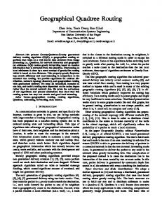
Fig. 1.
C2C-CC Architecture
wireless communication medium below the C2C layer but, for convenience, we assume only 802.11p in this paper. It’s not clear how the C2C layer can play the role of the sublayer for IPv6. The C2C layer is very different from traditional sub-layers like, i.e. Ethernet. There is neither clear-cut link nor generic link-scope multicast. [4] proposes to emulate a geographically defined Ethernet link within the C2C header. However, our proposal, instead of emulating Ethernet, exploits genuine C2C features to support IPv6. III. O BJECTIVES AND REQUIREMENTS For IPv6 to run over the C2C layer, two operations are needed, IP configuration and IP packet delivery. IP configuration is for a node to acquire necessary IP parameters for communication such as the IPv6 address and prefix information. IP packet delivery is for a node to efficiently deliver a packet to its destination using the C2C layer. A. IP configuration For IP configuration, a node should discover a reachable access router with a suitable prefix information as in RFC 4861 [24]. It also should acquire a valid IP address and be able to perform Duplicate Address Detection (DAD) as in RFC 4862 [29]. These operations are not difficult on an Ethernet link with link-scope multicast support. However, the C2C layer playing the role of IPv6 sub-layer lacks generic link-scope multicast support. Even the concept of link becomes extremely ambiguous there. It’s possible to artificially define a link and emulate Ethernet in the C2C layer but that would bring forth low efficiency and high complexity. Instead, we propose nodes to maintain two kinds of links: i) C2C link and ii) virtual point-to-point link. Each node forms a virtual point-to-point link with an access router through a C2C tunnel. Since this is a point-to-point link, the node can easily perform Neighbor Discovery and Stateless Address Autoconfiguration with DAD as in RFCs 4861 and 4862. For ordinary data transmission, the node uses the other C2C link. We’ll describe detailed IP configuration procedures in section IV.
B. IP packet delivery We briefly sketch the IP packet delivery framework in IPv6 over a C2C environment. Four main entities are involved in IP packet delivery: i) Source originates a packet and adds IPv6, C2C and 802.11p headers with suitable address and identifier. ii) L2 neighbors are the nodes which can communicate directly with one another over the wireless link, i.e. 802.11p. Take notice that the L2 neighbor is different from the IP neighbor. Usually neighbors on the IP link are the nodes on the same IP link. So there is a transitive relationship between neighbors. If node A and node B are neighbors and node B and node C are neighbors, node A and node C are neighbors. However such transitivity doesn’t hold for L2 neighbors in our definition. Upon generating an IP packet, a source chooses an L2 neighbor and forwards the packet to the L2 neighbor in the 802.11p frame. The chosen L2 neighbor is designated by the destination MAC address in the 802.11p frame. iii) IP next hop is the next hop from an IP viewpoint. Take notice that L2 neighbor is the next hop from an 802.11p viewpoint. IP next hop is the end node to which the packet is delivered by the C2C forwarding mechanism. IP next hop is a destination from a C2C viewpoint. Before IP next hop, all intermediary nodes only check the packet’s C2C header and ignore its IP header. Only IP next hop consults IP header to make a forwarding decision. If a destination is reachable through the C2C mechanism, the destination is IP next hop. If not, an access router is IP next hop. An IPv6 packet is encapsulated in the C2C header and IP next hop is designated by the destination C2C identifier in the C2C header. iv) Destination is the node to which IP packets are delivered and designated by the destination IPv6 address in the IPv6 header. A packet is generated from source, forwarded to L2 neighbor, then IP next hop and finally destination in that order. For example, in Fig.2, a packet is originated at node 1 and delivered to a corresponding node across an access router. Here node 1 is the source, node 2 the next L2 neighbor, access router the IP next hop and the corresponding node the destination.
Fig. 2.
IP packet delivery
Source generates an IPv6 packet with destination IPv6
Authorized licensed use limited to: TELECOM Bretagne. Downloaded on February 15,2010 at 09:37:41 EST from IEEE Xplore. Restrictions apply.
address, encapsulates it with the C2C header with IP next hop’s C2C identifier and encapsulates it once more with the 802.11p header with neighbor’s 802.11p MAC address as in Fig. 3. Take notice that the 802.11p header designates the neighbor, the C2C header designates the IP next hop and the IPv6 header the destination.
Fig. 3.
Packet encapsulation
For IP packet delivery, a source node performs two tasks: i) IP next hop determination is to find the IP next hop’s C2C identifier from a given destination IPv6 address. ii) L2 neighbor determination and address resolution is to find the next L2 neighbor’s C2C identifier and 802.11p MAC address from a given IP next hop’s C2C identifier. Traditionally these tasks require link-scope multicast support, but, in VANET environment, that is difficult and costly. So instead we rely on location management features in the C2C layer to perform those functions. The C2C layer maintains the information about communication peers. For example, a node manages the list of its L2 neighbors. Our proposal exploits this information maintenance features to resolve IP next hop and next neighbor information in the C2C layer without link-scope multicast. We’ll describe detailed IP packet delivery procedures in section V. IV. IP CONFIGURATION PROCEDURES For IP configuration, a node should discover a router which can provide an access to the Internet. The node should receive a Router Advertisement (RA) message to acquire a necessary IP parameter for global communication such as a valid prefix. In case of address autoconfiguration, the node should perform Duplicate Address Detection (DAD) to assure the address uniqueness. A. Link types In our proposal, a node manages two kinds of links i) C2C link and ii) virtual point-to-point link to an access router. C2C link is used for data transmission, i.e. IP packet delivery and virtual point-to-point link for signaling procedure, i.e. IP configuration. From IP viewpoint, it has two interfaces, one to C2C link of non-broadcast multi-access (NBMA) type and one to point-to-point link with an access router. Neighbor discovery messages [24] to the access router use the pointto-point interface. All other packets use C2C interface. This section describes a way to manage the point-to-point link. C2C link usage for packet delivery is provided in the next section. B. Access router search A node first should find an access router to the Internet. It should acquire IPv6 address, C2C identifier and geographic location of an access router. There are 3 ways to achieve this.
i) Map based Nowadays a vehicle is equipped with a navigation system containing a road map. We can include in this map the information of access routers along the roads. The map can contain roadside access routers’ IP address, C2C identifier and geographic location. With this map with access router information, a vehicle can choose a suitable access router by comparing its geographic location and access routers’. ii) Beaconing based An access router can send a beaconing message with a router flag to indicate that it’s an access router. Upon receiving this, a node can acquire necessary access router information. iii) RS/ RA based A node can send a Router Solicitation (RS) message to ask for a Router Advertisement (RA) message. An RS message can be delivered within a certain geographic area to reach an access router. A node can acquire necessary access router information with the above and moreover several enhancements are also possible for performance improvement. C. Virtual point-to-point link establishment Upon finding an access router’s C2C identifier, a node forms a virtual point-to-point link with the access router via C2C tunnel. The C2C tunnel end points are defined by its C2C identifier and the access router’s. Through this tunnel, the node sends the access router an RS encapsulated in C2C header. Upon receiving the RS from an unknown C2C node, the access router also forms a virtual point-to-point link with the same C2C tunnel and sends an RA through the tunnel. With this virtual point-to-point link, the node can perform Neighbor Discovery and Statelesss Address Autoconfiguration easily. Take notice that, if a node is attached to multiple access routers, the node manages different point-to-point links with different access routers. D. Stateless address autoconfiguration If the access router allows the node stateless address autoconfiguration, it includes a prefix with A-bit set in the RA as in [24]. For each node, the access router manages a separate virtual point-to-point link and assigns a different prefix. From the prefix, the node can configure an address and perform DAD as defined in [29]. Since it belongs to a point-to-point link, the operation is trivial as in IPv6 over 802.16 WiMAX case in RFC 5121 [26]. Such a configured global IPv6 address can be used in both point-to-point link and C2C link. Because a different prefix is assigned to a different node, there is no address conflict. However, we recommends nodes to restrict link-local address usage only for point-to-point link with an access router because its uniqueness is not guaranteed in C2C link. Also access routers may perform ingress filtering to drop packets with invalid source address, i.e. an address with a prefix which is not assigned by the router.
Authorized licensed use limited to: TELECOM Bretagne. Downloaded on February 15,2010 at 09:37:41 EST from IEEE Xplore. Restrictions apply.
TABLE I I NFORMATION ENTRIES FOR LOCATION MANAGEMENT
Location management Beaconing L2 neighbor list Location table
Destination cache Router list
Location service
IPv6 address Source Source Destination × Destination
C2C identifier Source Source Destination, IP next hop, L2 neighbor Router Destination
V. IP PACKET DELIVERY PROCEDURES In this section, we present IP packet delivery mechanism in detail. A. IP aware location management C2C layer maintains the location information of communication peers. It performs i) beaconing, ii) location table management and iii) location service. Beaconing is about to exchange geographic location information among L2 neighbors. Location table management is to record a communication peer’s geographic location and, possibly, a route to the peer. Location service is to resolve a communication peer’s geographic location from the peer’s identifier. We propose to make these location management functions be aware of IP information as below. 1) Beaconing: Each node sends a beaconing message with its interface. (IPv6 address, C2C identifier, 802.11p MAC address, geographic location). The beaconing message may also include time stamp, velocity vector, location information accuracy and other information to improve performance. 2) Location table: conceptually location table is divided into three sub-tables i) L2 neighbor list, ii) destination cache and iii) router list. However all three tables can be merged into one location table in implementation. i) L2 neighbor list L2 neighbor list maintains L2 neighbor information. L2 neighbor list records L2 neighbor’s (IPv6 address, C2C identifier, 802.11 MAC address, geographic location) . L2 neighbor list may also include time stamp, velocity vector, location information accuracy and other information to improve performance. L2 neighbor list is generated with beaconing messages from L2 neighbors. ii) Destination cache Destination cache records a route to a destination. Destination cache maintains the destination’s information, its IP next hop’s information and next L2 neighbor’s information. Destination cache records (Destination IPv6 address, Destination C2C identifier, IP next hop C2C identifier, IP next hop geographic location, L2 neighbor C2C identifier, L2 neighbor 802.11p MAC address). Destination cache is for performance enhancement. IP packet can be delivered even without destination cache but its presence greatly facilitates the data delivery. Take
Geographic location Source Sourse
802.11p MAC address Source Source
IP next hop Router Destination
L2 neighbor × ×
notice that, with an entry in the destination cache, IP next hop determination, L2 neighbor determination and address resolution is trivial. Given a destination IPv6 address, necessary IP next hop and L2 neighbor information can be found easily. In general, after sending a packet, a node records the destination, IP next hop, L2 neighbor information in destination cache for future use. iii) Router list Router list maintains the information of access routers which can provide an access to the Internet. Router list records (router C2C identifier, router geographic location). Router list may also include router IPv6 address and other information to improve performance. 3) Location service: Provides a destination’s geographic location from its identifier. When a source has only destination’s identifier but doesn’t know its geographic location, it relies on location service. It send a query with a destination’s identifier and location service replies with the destination’s geographic location. Detailed method to provide location service can be found in [22]. To map identifier to geographic location, location service manages 2-tuple of node’s (identifier, geographic location). In our scheme, location service manages 3-tuples of node’s (IPv6 address, C2C identifier, geographic location). When a source has only destination IPv6 address, it sends a query to location service with the IPv6 address and location service replies with the destination’s C2C identifier and its geographic location. [22] enlists various schemes for location service and all those can be easily modifies to deal with 3-tuples of (IPv6 address, C2C identifier, geographic location). Table 1 describes the IP aware location management functions and the information entities maintained by them. Take notice that there are 4 involving entities, i) source, ii) L2 neighbor, iii) IP next hop and iv) destination and 4 different information about them, i) IPv6 address, ii) C2C identifier, iii) geographic location and iv) 802.11p MAC address. B. Data transmission procedures In this section, with IP aware location management, we present a way for IPv6 packet delivery, i.e. a way to deliver an IPv6 packet to first L2 neighbor, then IP next hop and finally its destination. To send an IPv6 packet, next hop determination and address resolution are necessary. In Neighbor Discovery protocol
Authorized licensed use limited to: TELECOM Bretagne. Downloaded on February 15,2010 at 09:37:41 EST from IEEE Xplore. Restrictions apply.
[18], these functions are performed with link-local multicast message. However, our proposal uses IP aware location management to accomplish those functions without relying on link-local multicast message. In a source C2C layer with the functional blocks depicted in Fig.4, an IPv6 packet is encapsulated in C2C header with IP next hop’s C2C identifier and send to 802.11p layer with next neighbor’s 802.11p MAC address.
Fig. 4.
Functional block
We divide IP packet delivery into three cases i) Case 1: an entry in destination cache, ii) Case 2: no entry in destination cache but a reply from location service, iii) Case 3: no entry in destination cache and no reply from location service. 1) Case 1: an entry in destination cache : After a source generate an IPv6 packet, the packet is delivered to IP next hop determination module in C2C layer as in Fig.4. There the source consults its destination cache to see whether it has an entry for the destination IPv6 address. If there is an entry, the destination cache provides with the IP next hop’s C2C identifier, its geographic location and next L2 neighbor’s 802.11p MAC address. Take notice that, with IP next hop’s C2C identifier and its geographic location, underlying C2C forwarding mechanism can deliver the IPv6 packet to the IP next hop. C2C header for IP next hop is generated with its C2C identifier and its geographic location. The IPv6 packet is encapsulated in the C2C header and delivered to 802.11p layer with the next L2 neighbor’s 802.11p MAC address from the destination cache. 802.11p layer generates 802.11p frame with the next L2 neighbor’s MAC address, which encapsulates the C2C NET packet. This way, the IPv6 packet is forwarded to the next L2 neighbor, then IP next hop. In IP next hop and only there, the packet is delivered up to IP layer. If it’s the destination, the packet is sent to upper layer. If not, the IP next hop is an access router and the packet is forwarded to the destination in Internet with standard IP routing mechanism. 2) Case 2: no entry in destination cache but a reply from location service: Assume there is no entry for a given destination IPv6 address in the destination cache. C2C layer asks location service with the destination IPv6 address. Then location service replies with the destination’s C2C identifier
and geographic location. Take notice that this implies that the destination is its IP next hop. With the destination/IP next hop’s C2C identifier and geographic location, the packet can be delivered to the destination with underlying C2C forwarding mechanism as below. The source consults its geographic routing module and its L2 neighbor list to determine the next L2 neighbor to which it forwards the packet. The neighbor list also provides the 802.11p MAC address for the L2 neighbor. With these information, the packet is sent to the destination as described in Case 1. 3) Case 3: no entry in destination and no reply from location service: Assume there is no entry for a given IPv6 address in destination cache and location service provide no information for the destination either. Then the source assumes that the destination is unreachable with C2C forwarding mechanism and in Internet beyond an access router. As IP next hop for the destination, the source picks one access router from its router list with the access router’s C2C identifier and geographic location. With those information, the packet is delivered to the access router with underlying C2C forwarding mechanism as described in Case 2. VI. C ONCLUSION This paper presents a new way to run IPv6 in VANETs with geographic routing mechanisms, i.e. C2C-CC environment. The solution exploits inherent location management features to perform basic IPv6 protocols such as Neighbor Discovery and Stateless Address Autoconfiguration. Our scheme enables efficient IP configuration and IP packet delivery procedures without link-scope multicast. Vehicles can configure global IPv6 address and, with the address, communicate with peers on and off-VANET. R EFERENCES [1] E. Baccelli, K. Mase, S. Ruffino, and S. Singh. Address Autoconfiguration for MANET: Terminology and Problem Statement. Internet-Draft draft-ietf-autoconf-statement-04, Internet Engineering Task Force, Feb. 2008. Work in progress. [2] F. Bai, N. Sadagopan, and A. Helmy. Important: a framework to systematically analyze the impact of mobility on performance of routing protocols for adhoc networks. 2003. [3] R. Baldessari, T. Ernst, and M. Lenardi. Automotive Industry Requirements for NEMO Route Optimization. Internet-Draft draft-ietf-mextnemo-ro-automotive-req-00, Internet Engineering Task Force, Feb. 2008. Work in progress. [4] R. Baldessari, A. Festag, W. Zhang, and L. Le. A MANET-centric solution for the application of NEMO in VANET using geographic routing. In Proc. of th Weedev, Austria, 2008. [5] M. Behringer. Analysis of the Security of BGP/MPLS IP Virtual Private Networks (VPNs). RFC 4381, Internet Engineering Task Force, Feb. 2006. [6] C. Bernardos, M. Calderon, and H. Moustafa. Survey of IP address autoconfiguration mechanisms for MANETs. Internet-Draft draft-bernardosmanet-autoconf-survey-02, Internet Engineering Task Force, Oct. 2007. Work in progress. [7] L. Breisemeister. Group Membership and communication in highly mobile ad hoc networks. PhD thesis, School of Electrical and Computing Science, Tecnhical University of Berlin, 2001. [8] Car-to-car communication consortium: http://www.car-to-car.org. [9] I. Chakeres and M. Belding-Royer. AODV routing protocol implementation design. In Proceedings of the International Workshop on Wireless Ad Hoc Networking (WWAN), Tokyo, Japan, 2004.
Authorized licensed use limited to: TELECOM Bretagne. Downloaded on February 15,2010 at 09:37:41 EST from IEEE Xplore. Restrictions apply.
[10] I. Chakeres, J. Macker, and T. Clausen. Mobile Ad hoc Network Architecture. Internet-Draft draft-ietf-autoconf-manetarch-07, Internet Engineering Task Force, Nov. 2007. Work in progress. [11] L. Chen, J. Steenstra, and taylor K-S. Geolocation-based addressing method for IPv6 addresses. Patent, Qualcomm Incorporated, January 2008. [12] V. Devarapalli, R. Wakikawa, A. Petrescu, and P. Thubert. Network Mobility (NEMO) Basic Support Protocol, January 2005. IETF RFC3963. [13] S. Eichler. Performance evaluation of the IEEE 802.11p WAVE communication standard. In Proceedings of the 1st IEEE International Symposium on Wireless Vehicular Communications (WiVeC), 2007. [14] T. Ernst. The Information Technology Era of the Vehicular Industry. ACM SIGCOMM Computer Communication Review (CCR), Volume 36(Issue 2), April 2006. [15] Geonet project: http://www.geonet-project.eu. [16] S. Jiang. An enhanced prediction-based link availability estimation for MANETs. IEEE Transactions on Communications, 52(2):183–186, 2004. [17] S. Jiang, Y. Liu, Y. Jiang, and Q. Yin. Provisioning of adaptability to variable topologies for routing schemes in MANETs. IEEE Journal on Selected Areas in Communications, 22:1347–1356, 2004. [18] J. Kempf. Goals for Network-Based Localized Mobility Management (NETLMM). RFC 4831, Internet Engineering Task Force, Apr. 2007. [19] L. Kleinrock and F. Tobagi. Packet switching in radio channels: Part I – carrier sense multiple-access characteristics. IEEE Transactions on Communications, 23(12):1400–1416, 1975. [20] S. KrauB. Microscopic Modeling of Traffic Flow: Investi- gation of Collision Free Vehicle Dynamics. PhD thesis, Mathematisches Institut, Universitat zu Koln, 2001. [21] C. Maihfer. A survey of geocast routing protocols. IEEE Communications Surveys and Tutorials, 6, 2nd quarter 2004. [22] M. Mauve, J. Widmer, and H. Hartenstein. A survey on positionbased routing in mobile ad hoc networks. IEEE Network Magazine, November/December 2001. [23] T. Nadeau and H. van der Linde. MPLS/BGP Layer 3 Virtual Private Network (VPN) Management Information Base. RFC 4382, Internet Engineering Task Force, Feb. 2006. [24] T. Narten, E. Nordmark, W. Simpson, and H. Soliman. Neighbor Discovery for IP version 6 (IPv6). RFC 4861, Internet Engineering Task Force, Sept. 2007. [25] T. G. p. IEEE P802.11p: Wireless access in vehicular environments (WAVE). draft standard ed., IEEE Computer Society, 2006. [26] B. Patil, F. Xia, B. Sarikaya, J. Choi, and S. Madanapalli. Transmission of IPv6 via the IPv6 Convergence Sublayer over IEEE 802.16 Networks. RFC 5121, Internet Engineering Task Force, Feb. 2008. [27] C. SCC32. IEEE P1609.4 standard for wireless access in vehicular environments (WAVE) - multi-channel operation. draft standard ed., IEEE Intelligent Transportation Systems Council, 2006. [28] T. Schulze and T. Fliess. Urban traffic simulation with psychophysical vehicle-following models. In Proceedings of Winter Simulation Conference (WSC), 1997. [29] S. Thomson, T. Narten, and T. Jinmei. IPv6 Stateless Address Autoconfiguration. RFC 4862, Internet Engineering Task Force, Sept. 2007. [30] J. Vare, J. Syrjarinne, and K.-S. Virtanen. Geographical positioning extension for IPv6. In Proc. of the ICN, Guadeloupe, 2004. [31] R. Wiedemann. Modelling of RTI-Elements on multi-lane roads. Comission of the european community, Advanced Telematics in Road Transport, 1991. [32] L. Wischhof, A. Ebner, M. Rohling, H. Lott, and R. Halfmann. SOTIS a self-organizing traffic information system. In Proceedings of IEEE Semiannual Vehicular Technology Conference, 2003.
Authorized licensed use limited to: TELECOM Bretagne. Downloaded on February 15,2010 at 09:37:41 EST from IEEE Xplore. Restrictions apply.