I RIS: a firmware design methodology for SIMD architectures Jan Jacobs Oc´e Technologies BV, PO Box 101, 5900MA Venlo, The Netherlands
[email protected]
Leroy van Engelen, Jan Kuper, Gerard J.M. Smit University of Twente dept EEMCS, PO Box 217, 500AE Enschede, The Netherlands
Rui Dai National University of Singapore Design Technology Institute Faculty of Engineering, 10 Kent Ridge Crescent, Singapore 119260 Abstract Developing code for SIMD type hardware architectures is a tedious job. This is caused by the absence of both a coherent methodological framework and a hardware independent tooling. Moreover, the inherently difficult nature of programming dedicated massively parallel embedded processors, complicates the matter. This paper describes a single framework, called I RIS, to generate code for SIMD architectures. This framework is illustrated with a concrete case ”Stochastic Image Quantisation”. I RIS is based on an incremental construction of executable representations, which converge to the final target implementation in a semi-automated way.
1 Introduction Nowadays embedded systems manufacturers are facing tough problems in developing high performance applications. The ever growing functionality of applications combined with new programmable many-core processors increase the development complexity. Therefore Patterson [2] states: ”Although compatibility with old binaries and C programs are valuable to industry ... we welcome new programming models and new architectures if they simplify efficient programming of such highly parallel systems”. In addition to this we believe that parallelism not always can be derived automatically from sequential code with enough quality: we need the option to code the parallelism explicitly by the application programmer. In this paper, we focus on a methodology that improves the programmer’s efficiency for Single Instruction Multiple Data (SIMD) architectures. The development of applications for SIMD
architectures needs special attention because: (1) massive parallelism cannot be expressed adequately by current languages, (2) variables can have all bit dimensions (e.g. 10 bit integers), and (3) data dimensions of the problem and the limited memory resources on a processing element do not match in general (requiring tiling). The de facto way applications are programmed on such dedicated systems is by manually adapting sequential code, which is mostly written in C. This adaptation involves the replacement of the time critical sequential parts by parallel code. Most tooling is supplied by the manufacturer of the processor hardware and is, to no suprise and without exception, a C-compiler supporting intrinsic instructions (hardware dependent predefined functions). This means that the design can only be validated at the end of the development cycle, when finally the code becomes available. Striking examples which demonstrate the weaknesses of the current approach are analysis and design faults that are discovered in late phases of the development. Thus we propose a methodological framework for SIMD firmware development that should at least: a. be an integral design method that supports firmware development for the whole trajectory (from problem-scouting till maintenance), b. be interactive and be executable during the whole development process, c. be incremental, enabling elaboration on the current state of the design, d. supporting reuse to improve quality and efficiency, e. be domain independant, i.e. be applicable to multiple application domains. In this paper we propose a methodological framework, called IRIS, that satisfies all these requirements. As a crucial feature of IRIS we assume that the same language is
available during the complete design process, which supports executability at all stages. We call such a language an architectural language. We propose an architectural language that is close to mathematics and understandable for the developer, leading to readable and compact code without any reference to implementation in early phases and with concise description of details in later phases. A single language supporting these multiple roles is a necessity in IRIS. First we give an overview of related work (Section 2), next we describe the IRIS methodology (Section 3). We briefly introduce the case (Section 4), followed by an elaboration of the case using IRIS (Section 5). Finally we present and discuss the results (Section 6) and the conclusions (Section 7).
2 Related Work An influential development approach for hardwaresoftware co-design, the Y-chart [10], is based on concurrent elaboration on multiple domains (coupled to stakeholders) at different abstraction levels. These domains, which in fact are different views for specifying a hardware system, are: behavioural (functional), structural (hierarchy of interconnected components, computer architecture) and the physical/geometrical domain (physical placement in space and physical characteristics). It is a very generic methodology, mostly used for hardware development but not well suited for developing code for existing many-core programmable processing systems. The ”Iterative Design Methodology” [8], puts emphasis on the iterative aspect in hardware software co-design. The extra-functional design properties as performance, power and resource consumption, are analysed by using postmapping analysis tools. However, for interactive code development we need instant mapping analysis. In addition to the common direction for functional development, in [14] an orthogonal direction, namely that of design space exploration is introduced. Design Space Exploration is a structured way of identification and evaluation of design alternatives, and the development of criteria. The ultimate choice, which is part of decision recording, starts off a next development cycle. Agile methods such as Extreme Programming (XP) [4] try to reduce development time, typically from months to weeks, by reintroducing interactivity to the design process. These methods, however, mostly use an implementation language for the development roles. This leads to less readable and maintainable code in particular for the early phases. Recently [11] more emphasis is put on raising the level of abstraction by using new parallel languages instead of extending the traditionally used sequential languages (mostly C-based). However, these languages lack
functionality
implementation
initial tech scope probe familiarisation
functional architecture complete
incremental prototyping
transformational development
realisation complete
time
production
Figure 1. Design dimensions in IRIS possibilities for the detailed control at elementary processor level. Platform based design [13] recognises the importance of both top-down and bottom-up development dimensions. For Image Processing applications, Bagdanov [3] advocates the separation of development and implementation in large Object Oriented frameworks (Horus). He selected a functional language for application development and C++ for implementation. From the software economics side it is known since long that two relevant issues influence the choice of a development methodology and in particular of the architectural language. First, the cost of reworking the software is much smaller (by factors up to 200) in earlier phases than later phases [7]. Second, the length of description is the dominant factor in software development costs [6]. The shorter the description the better, giving credit to declarative languages (e.g. functional languages). None of the above approaches fulfills all requirements mentioned before.
3 The IRIS Methodology The IRIS design methodology, for deriving firmware for SIMD architectures should support different application domains and should be strongly phased, to allow for the different development roles, see Figure 1. In Section 5 the methodology will be illustrated with a case study. In our methodology we recognise three main phases: I) Familiarisation, II) Incremental prototyping, and III) Transformational development. I. Familiarisation. The goal of this phase is to come up with a provisionary demarcation of the system boundary and some confidence on the feasibility with respect to the intended hardware. This actually corresponds to the design activities normally deployed between the behavioural and the structural domains in the Y-chart methodology [10]. The physical domain is absent in our approach since we assume
that the (many-core) hardware technology is already available. We start with the scouting of both the problem (initial scope) and the intended hardware architecture (tech probing). In order to maximise the degree of freedom for system development an abstract ’mathematical’ description is made of the formulated problem. At the same time models are made of the target hardware – partly based on sample programs provided by the hardware supplier – to better understand its behaviour. Both activities use the architectural language. At the end of this phase, when sufficient confidence has been built up in both application and hardware architecture, the choice of the hardware is fixed. However, some parameters such as number of processors, clock frequency, size of memories, may change at a later stage. Actual code production consists of the following two phases: incremental prototyping and transformational development. II. Incremental prototyping. The goal of this phase is to establish the specification of the system. This phase leads via a number of intermediate steps to a complete specification, the Functional Architecture, and to a validation testset, a baseline set used in next phases. This specification is executable –as all the intermediate steps–, is independent of the target hardware, and serves as a live description of the system. The functional architecture marks an important milestone in the customer-architect co-operation. At this point we know the desired functionality of the system and we can turn to the transformational development, which is hardware architecture dependent. III. Transformational development. The goal of this phase is a satisfactory realisation of the desired functionality on the selected hardware architecture. This phase consists of behaviour preserving transformations (except for the trade-off subphase), which progressively involves making design choices determined by the hardware architecture used, see Figure 1 (right part). The validation testset is progressively extended at the same pace as the functional decomposition. This allows intermediate checking against the current complete validation testset. The Transformational Development phase exhibits the following subphases: Trade-off, Reorganisation, Template, and Translation. Trade-off. The goal of this subphase is to deliver a golden reference, which can be used for validation purposes for downstream transformations. Because of hardware limitations often concessions have to be made to the accuracy of computations, bit-width of variables, or even computation speed. Because of possible (mostly tiny) concessions made to the functionality, this subphase involves, besides architect and implementor, also the customer. Reorganisation. The goal of this subphase is to rephrase the executable model in a top-down manner such that it is more geared towards the chosen hardware architecture. This and following subphases involve only behaviour pre-
serving transformations. Template. The goal of this subphase is to identify reusable components which can reduce current and future work. These components may consist of common code fragments or even complete modules. The development direction is bottom-up, showing the abstraction of a code fragment (as a template instance) to the template. Both reorganisation and template subphases address the platform based issues [13]. Translation. The goal of this subphase is to realise a smooth transition to the target hardware. This involves a fully automatic translation from the model of the design coded in the architectural language, following the template and all earlier subphases, into the native target language (mostly C+intrinsics) of the chosen hardware. The unique contribution of IRIS to the field of developing firmware for a SIMD architecture is – to the best of our knowledge – that the framework is: integral, interactive, incremental, domain independent, and utilises a single architectural language that is close to mathematics and understandable by a developer. The IRIS framework depends heavily on the right choice of this architectural language. The language should be: (a) flexible, in the sense that it supports modelling of high level descriptions (close to mathematics) as well as implementation issues as data parallelism or even low level bit field assignments, (b) compact, since compactness of description is a virtue in reducing costs (c) executable, to offer verifiability of work in all phases, (d) interpretative, in order to realise the needed interactivity, and (e) general purpose, to allow for creating auxiliary tooling, such as memory utilisation or performance monitoring. In IRIS we use a functional language (like Haskell [5] of J [16]) as the architectural language because it fulfills the requirements mentioned above. We believe in a single architectural language for all phases that supports multiple roles because of ease of use: (1) one single framework is better facilitated by a single language provided the different roles involved can be served adequately, (2) a language close to mathematics facilitates precise specifications, (3) the language should facilitate concise description of implementation details, (4) code refactoring (for example in the Template subphase) is hindered when interfaced over cross-language domains, and (5) one language to investigate and document suitable alternatives is more beneficial than using different languages. It turned out that a functional language best satisfies the above mentioned properties and the requested support for multiple roles.
4 Case study We illustrate the IRIS methodology with stochastic image quantisation on an SIMD architecture [12] in Section 4.1. Other applications which were developed using IRIS are colour image processing for a printer, mining and visualising document spaces and raster detection, but are not discussed here. In Section 4.2 we present the target SIMD hardware architecture, the Linedancer of Aspex, followed by a functional view on the hardware (Section 4.3).
4.1
Stochastic Image Quantisation
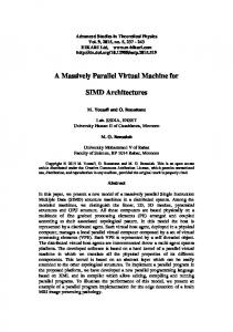
Business graphics are characterised by its use of relatively few colours, and relatively large areas having the same colour. The result of scanning business graphics often shows undesired variations in colour in such single coloured areas. To improve the quality of the scan we use a technique called stochastic image quantisation and which is used in combination with simulated annealing (see [9]). The scan process samples an original and returns a matrix of colours of pixels. In the context of this paper we assume, without loss of generality, that all colours are greyvalues. The matrix typically has a size of 5000 × 7000 pixels, whereas grey-values typically fall in the range 0..255. An example of a histogram for grey-values is shown in Figure 2. The objective of image quantisation is to assign all
µ0
µ1
µ2
µ3
0
255
pixels in class gs 0
1
2
3
Figure 2. Histogram of grey-values pixels to a limited number of classes. Let L be the number of classes, in Figure 2 L = 4. Let s be a pixel, then γs denotes the grey-value of s, whereas gs denotes the class to which s is assigned. Let S be the set of all pixels, then the mean of a class c is µc : µc = mean{γs | s ∈ S , gs = c}
f idg (s) = (γs − µgs )2
(2)
Thus, the fidelity of a pixel s is the square of the difference between the actual grey-value γs of s and the mean greyvalue µgs of the class to which s is assigned. The lower f idg (s) is the better the class mean fits the scanned image pixel. A second quality criterion is regularity which expresses the property of business graphics that relatively large areas have the same colour. That is, regularity indicates how well the grey-value of a pixel fits in its immediate surroundings. Let s = (i, j). Then we define p Ns = {(k, l) | (k − i)2 + (l − j)2 ≤ R, (k, l) 6= (i, j)} as the neighbourhood Ns of pixel s. Thus, Ns contains all pixels within distance R from s, except s itself. Let gr be the class of a pixel in the neighbourhood of s. Then the regularity is defined by: regg (s) = | {r ∈ Ns | gs 6= gr } | − | {r ∈ Ns | gs = gr } | (3) The lower regg (s) is, the more uniform the neighbourhood is. Thus, the quality criterion per pixel, energy, combining fidelity f idg (s) and regularity regg (s), is defined by eg (s):
grey-value histogram
grey-value pixels γs of
quality measure. The method of simulated annealing repeatedly assigns a new class c0 to each pixel s in a random way, compares the result with the previous assignment, and chooses the best. A quality function is used to chose between the new class gs = c0 or the old one gs = c. After several iterations this process leads to an optimal quality. One specific quality criterion per pixel, given the class assignment function g, is the so-called fidelity:
(1)
Stochastic image quantisation [15] now takes (the nearest integer to) µc as the best grey-value for class c. However, the question which pixel should be assigned to which class is not so easy to answer. The final answer to that question is determined in an iterative way and depends on a certain
eg (s) = f idg (s) + β · regg (s),
(4)
where the weight β > 0 allows for a better, image dependent, quantisation. The value for β is determined experimentally and is in most cases an integer in the range [1, 100] [15]. The quality criterion for the complete image is defined by the matrix Eg (S ): Eg (S ) = [[eg (s)]]s∈S ,
(5)
This matrix Eg (S ) is used by the simulated annealing procedure to produce the final quantisation matrix g(S ). Since the value eg (s) of each pixel must be minimised, quality is defined as the negated sum of all energies per pixel: Qg (S ) = − ∑ eg (s) = − ∑ f idg (s) + β · regg (s) s∈S
(6)
s∈S
This quality is used during development to make motivated choices for various design parameters.
5.1
Program Associative String Processing array (ASProCore) network cascadable over chips
Inter-PE communication network
PE 4,095
PE 4,094
Thousands of PEs
PE 4,093
PE 2
PE 1
Common instruction Bus
PE 0
On-chip RISC
On-chip or Off-chip memory
Figure 3. The scalable architecture of the Linedancer
4.2
Linedancer
Aspex’s Linedancer [1] is an implementation of a parallel associative processor. The processor contains 4096 simple processing elements in a SIMD arrangement (ASProCore), see Figure 3. The control is centralised in a RISC processor (SPARC). Each of these processing elements (PEs) on the Linedancer device has about 200 bits of memory (of which 64 bits are fully associative) and a single bit ALU, which can perform a 1 bit operation in a single clock cycle. Operations on larger bit-fields, specified by a start location and a field length, take multiple clock cycles. Multiple Linedancer devices can be connected together to create an even wider SIMD array, allowing a scalable solution. A Linedancer is programmed in an extended version of C, with additional functions for controlling the ASProCore. The Linedancer processor is chosen because it fits a pixel parallel model well (scalable in number of pixels) and the associative functionality facilitates the necessary table lookups for the quantisation class means.
After the familiarisation phase (Figure 1), we turn to the stepwise creation of a complete functional model based on the mathematical model of the system as given by the equations (1) – (6). This model can be immediately transcribed in a functional language such as Haskell (see [5]) by defining the corresponding functions: mu c = mean [ gamma s | s