We present a faster and simpler approach for the calculation of iron and magnet losses and torque of an interior permanent-magnet synchronous machine ...
IEEE TRANSACTIONS ON MAGNETICS, VOL. 46, NO. 12, DECEMBER 2010
4073
Iron and Magnet Losses and Torque Calculation of Interior Permanent Magnet Synchronous Machines Using Magnetic Equivalent Circuit Abdul Rehman Tariq, Carlos E. Nino-Baron, and Elias G. Strangas Department of Electrical and Computer Engineering, Michigan State University, East Lansing MI 48824 USA We present a faster and simpler approach for the calculation of iron and magnet losses and torque of an interior permanent-magnet synchronous machine (IPMSM) than finite-element methods (FEM). It uses a magnetic equivalent circuit (MEC) based on large elements and takes into account magnetic saturation and magnet eddy currents. The machine is represented by nonlinear and constant reluctance elements and flux sources. Solution of the nonlinear magnetic circuit is obtained by an iterative method. The results allow the calculation of losses and torque of the machine. Due to the approximations used in the formulation of the MEC, this method is less accurate but faster than nonlinear transient magnetic FEM, and is more useful for the comparison of different machine designs during design optimization. Index Terms—Accuracy, efficiency, magnetic scalar potential, permanent magnets, permeability, permeance, reluctance, saturation.
I. INTRODUCTION
H
IGH-POWER interior permanent-magnet synchronous machines (IPMSMs) are used extensively in hybrid vehicles as traction drives due to their high power density, wide speed range, and high efficiency. To compute and maximize the average efficiency of the drive, efficiency maps for the traction motors should be generated [1] to help match a drive with its application. An optimized machine design is usually the outcome of many design iterations, and machine power losses (copper, iron, and magnet) are computed to build the efficiency map for each iteration. Analytical methods presented by Mi et al. [2] and Roshen [3] cover stator iron losses for permanent-magnet (PM) machines. Dlala [4] proposed a calculation method based on the modeling of the – curve and the magnetic properties of the lamination material. Roshen presented an accurate method of core losses calculation for ac machines that addresses nonsinusoidal waveforms as well [5], [6]. The method is based upon a piecewise linear modeling of the flux density in the time domain. FEM is generally used to calculate iron losses with better accuracy. Computation of iron losses components for PMSMs were given by Yamazaki and Seto [7] with improvements proposed by Seo et al. [8] using variable iron loss coefficients. A dynamic loss model of the lamination material is presented by Belahcen and Arkkio in [9] to calculate the iron losses of electrical machines using FEM. To build efficiency maps, repeated calculations of machine losses by nonlinear time-stepping FEM takes hours. A widely used fast analytical machine design software tool (SPEED) includes a module that provides rapid sizing and calculates the performance characteristics of PM machines based upon linear characteristics of the material [10]. Calculation of the iron losses under magnetic saturation is handled by interfacing of SPEED with FEM [11]. Manuscript received April 21, 2010; revised August 19, 2010; accepted August 30, 2010. Date of publication September 09, 2010; date of current version November 30, 2010. Corresponding author: A. R. Tariq (e-mail: tariqabd@msu. edu). Color versions of one or more of the figures in this paper are available online at http://ieeexplore.ieee.org. Digital Object Identifier 10.1109/TMAG.2010.2074207
The magnetic equivalent circuit (MEC) or reluctance network analysis (RNA) and its application for electrical machines were introduced by Ostovic´ [12]. Improvements were made in MEC/RNA to estimate the performance of electromagnetic devices and electrical machines [13]–[21]. Performance analysis using MEC is receiving more attention, especially during the early design optimization. Its key advantages are the higher accuracy than the analytical and lumped parameter models and lower computational time than FEM. The majority of the work based on MEC addresses induction and switched reluctance machines and electromagnetic actuators [13]–[21]. Kim et al. [13] calculated the static characteristics of a linear brushless dc machine using MEC, neglecting the reluctance of the iron core. RNA-based iron loss calculation of a switched reluctance motor in [14] utilized an analytical function to approximate the – curve of the iron core. Perho presented RNA based performance analysis of an induction machine using a – curve approximated by a third-order function [15]. MEC was also used to model a voltage fed induction machine [16] in the frame of reference for different operating conditions. Derbas et al. [21] compared mesh-based to node-based analysis of nonlinear magnetic circuits. To improve the accuracy of the MEC/RNA and to capture the effects of saturation, leakage, and fringing of the flux, refinement of the elements was used. The switched reluctance machine was studied in [17], and an electromagnetic actuator in [18]. 3-D MEC was introduced in [19], [20], and encouraging results were obtained for an induction machine. Increasing the number of elements and using 3-D networks for MEC provides better accuracy, and development of MEC in this direction may replace the need of FEM. However, MEC will lose its key advantage of faster calculation due to increased size of the system of equations [15]. A lumped parameter model for flux switching PM machine by Zhu et al. [22] was used to calculate back electromotive force (EMF), stator inductance, and developed torque. A comparison between lumped parameters and FEM for the calculation of and axes inductances in PM machines was discussed in [23]. More detailed work was presented in [24] for the calculation of and axes inductances and torque for saturated IPMSM. Recent work on IPMSM by Zhu et al. [25] shows good match
0018-9464/$26.00 © 2010 IEEE
4074
of fundamental air gap flux density compared with that of FEM for no load, neglecting the reluctance of stator and rotor iron, and using fixed saturation level in the bridges. Analysis at a varying load will need further refinement of the elements due to saturation of the iron core. Our approach for modeling of MEC starts with that in [12] with a number of improvements and adaptations. IPMSMs, especially those having multilayered magnets and nonsymmetric elements of rotor geometry, operate in deeper saturation than induction and switched reluctance machines. Iron and magnet loss calculations of IPMSM using MEC have not been explored much in the past and this paper contributes towards this objective. The proposed method is expected to be fast and have comparable results with FEM. A simple 2-D MEC model of a radial flux IPMSM based on the limited and large iron core elements is used that works well for no-load as well as for varying load conditions. The – curve of the iron core material was modeled using cubic splines. The iron core and air gap are divided into saturating and nonsaturating elements, respectively. The winding current and magnets are represented by magnetomotive force (MMF) and flux source. Re-meshing of air gap elements with stator and rotor elements nodes is performed at every time step. Time-dependent solution of the flux leads to the calculation of iron and magnet losses and torque of the machine. Reduced accuracy due to the use of large core elements is compensated for in ways that avoid increasing the element count and prolonging solution: data points of – curve are used instead of an approximated analytical function, considerations are developed that lead to a careful design of elements and element sizes, and a new type of element is proposed that has two possible axes of flux for areas where the direction of flux varies in the time domain. We have presented an overview of our earlier work on this topic [26]. Here, the MEC method is discussed in detail, including the considerations for the creation of elements, improvement in the iron losses algorithm, and torque calculation. Magsoft’s Flux 2D, a commercial software package has been used as FEM tool. Solution of MEC and losses calculation is worked out using Matlab. Although the proposed method requires the geometrical dimensions of all elements of the MEC, most elements of the IPMSMs are symmetrical. The programming effort for each design iteration is primarily to enter the dimensions of only a few elements in the Matlab program. Each machine presented in this paper took about 10–15 min for this task. Furthermore, the dimensions of elements for each run can be generated automatically through parametrization. The overview of MEC approach for IPMSMs is presented in Section II. Considerations for the creation of elements are described in Section III. Development of mathematical model of MEC for a typical IPMSM and its solution is discussed in Section IV. Calculation of the iron and magnet losses are explained next in Section V. Application of the MEC method to two different machines, calculation of torque, and comparison with FEM results are presented in Section VI. Finally, conclusions in Section VII, give a summary and discuss potential utilization of the proposed method.
IEEE TRANSACTIONS ON MAGNETICS, VOL. 46, NO. 12, DECEMBER 2010
II. MEC APPROACH The first task of MEC is to divide the machine geometry into enough elements to reflect all its electromagnetic properties. The number of elements should allow the solutions of the MEC with reasonable accuracy in time significantly lower than FEM. Each magnet is represented by a flux source and a parallel nonsaturating reluctance [12]. Similarly, current carrying stator windings are modeled by time varying MMF. The iron core and air gap are divided into rectangular elements. The permeance of a uniform material is given by
(1) where , are area and length of the elements, and , are the permeability of free space and relative permeability, respectively. In order to determine the length and area of each element, the expected flux direction and its variation are established first. One side of every element is along the axial direction and it is equal to the stack length of the machine. The other side of the area is the element width. The length of each element is taken along the flux direction. varies widely and it is Due to the magnetic saturation, recalculated for all saturated elements at each iteration of every time step. The geometry of air gap elements and their interface with stator and rotor elements also varies at each time step due to machine rotation. III. FORMATION OF ELEMENTS The machine geometry is divided into large elements so that the magnetic flux can be approximately uniform in each element at any instant. The geometry of elements, with the exception of those in the air gap, is invariable. Stator teeth and back iron elements are symmetric. Rotational symmetry is also used to minimize the number of elements. A. Stator Elements The stator elements for one quarter of a three-phase, fourpole, 24-slot, 20-kW IPMSM are shown in Fig. 1. Each tooth is taken as one element, and its length is equal to the depth of the slot. The flux direction in every stator tooth remains along its length, radial to the axis of rotation. Since the width of stator teeth is not uniform along its length, it is taken as the weighted average of the teeth segments. A back iron element is created between every two adjacent teeth. The width of each element is the difference of the outer and the inner radius of the yoke. Its length is the weighted average of minimum and maximum arc distances in the yoke, which correspond to the inner and outer yoke radii. B. Rotor Elements The flux paths in the rotor are more complex than in the stator. The flux direction in the rotor elements varies significantly with the magnitude and phase of the load current as shown in Fig. 2,
TARIQ et al.: IRON AND MAGNET LOSSES AND TORQUE CALCULATION OF IPMSMs USING MAGNETIC EQUIVALENT CIRCUIT
4075
Fig. 1. Large elements of a quarter stator. (a) Elements. (b) Geometry.
Fig. 2. Rotor flux lines and location of specific elements: 1 = Saturated bridges, 2 = Nonsaturating bridges, 3 = Variable flux direction. (a) No load. (b) Full load.
and this is reflected in the type and geometry of elements of Fig. 3 discussed in this section. 1) Permanent Magnets: Are represented by a linear permeance in parallel with a flux source. Air pockets between the magnets are also represented by linear permeance. Half of each air pocket permeance is added to the permeance of the magnet on its each side. This results in one permeance parallel to each flux , , , and . source as shown by 2) Bridges: Are the narrow flux paths of iron core between two magnets, and between a magnet and rotor edge. Deeply saturated bridges (outer layer rotor edge) are represented by an . Bridges near rotor edge of inner equivalent air permeance magnet layer are not fully saturated and are treated as saturating . Similarly, the permeance between the magnets permeance , each half is are saturating too, and they are split into two in parallel with the magnet on its side. 3) Rotor Iron Between Outer Magnet Layer and Air Gap: Has varying flux direction due to varying rotor position and load current, but much less than the other rotor elements. The flux direction in this part is modeled as perpendicular to the magnet and elements. The width of each of these thickness in elements is equal to one third of the total arc length of the rotor surface in front of the outer magnet layer. These three permeances have a common node on the rotor surface. 4) Rotor Iron Between Magnet Layers and Around Shaft: Has flux direction that varies from the perpendicular to tangent to the magnet surface. To include this effect, the iron core of rotor is “counted” twice in the formulation of elements. The first time it is assumed that the flux path is along one direction, i.e.,
Fig. 3. Large elements of a quarter rotor. (a) Elements. (b) Geometry.
perpendicular to the magnet thickness. Here, the iron core is divided into elements , , , , , , , , , and . The second time the flux path is modeled as tangential to the magnet thickness. This results in the formation of , , , , , , , , and . Apelements plying this approach, the dimensions of all rotor elements are calculated and are listed in Table I. 5) Air Gap: Between stator and rotor are modeled as rectangular linear elements of length equal to that of the air gap. Their width is the air gap arc of the overlapping angle of stator and rotor elements, and it varies at every time step due to machine rotation. Between nonoverlapping stator teeth and rotor elements, the air gap permeance is zero. IV. DERIVATION AND SOLUTION OF MEC The MEC model of one pole pair is shown in Fig. 4. The physical connection between the left and right ends of the magnetic circuit is modeled through common variables. To simplify the MEC, two permeance elements in series with each flux source are combined to one element. A linear leakage permeance exists
4076
IEEE TRANSACTIONS ON MAGNETICS, VOL. 46, NO. 12, DECEMBER 2010
TABLE I LENGTH AND WIDTH OF THE ROTOR ELEMENTS
Fig. 4. Magnetic equivalent circuit of a pole pair of an IPMSM.
between every two stator teeth due to stator slot opening. The MMF source of the stator teeth depends on the winding configuration, coil pitch, number of turns, and input current. In order to calculate the flux through each element of Fig. 4, the magnetic scalar potential (MSP) of each node is computed
first by solving the MEC. Taking one node as reference, we write a system of equations in vector notation [12]
(2)
TARIQ et al.: IRON AND MAGNET LOSSES AND TORQUE CALCULATION OF IPMSMs USING MAGNETIC EQUIVALENT CIRCUIT
where is matrix of linear and nonlinear permeance, is vector of MSP of the nodes, and is vector of flux flowing into the nodes. The nonlinear system (2) was solved iteratively for every time step using successive over relaxation (SOR) method [27]. The stator nodes position was fixed, however, the rotor surface nodes were moving due to machine rotation, and their position was tracked in the solution of MEC. The overlap angle between stator and rotor nodes varied at each time step, and this affected the reluctance and connections of the air gap elements. Linear reluctance elements (other than in the air gap) were calculated only once, while the air gap reluctance was computed for every time step. The relative permeability of saturated elements was adjusted in every iteration. A cubic spline interpolation was used to represent the curve from discrete – data points and flux density was calculated from the MSP of the nodes.
4077
Fig. 5. Iron loss; provided by manufacturer and recalculated by coefficients.
V. CALCULATION OF IRON AND MAGNETIC LOSSES A. Iron Losses The iron losses were calculated by post processing of the MSP of the nodes of MEC. In FEM transient magnetic application, iron losses per unit volume for each element of iron core at one time instant “ ” and over one cycle of electrical frequency “ ” are given by (3) and (4), respectively [28] Fig. 6. Eddy-current flow in the magnets.
(3) original losses curve and as it is recomputed using the calculated coefficients. B. Losses in the Permanent Magnets (4) where Coefficient of hysteresis losses W/T s
m .
Coefficient of excess losses W Ts
m .
Conductivity of laminations
m
.
Thickness of laminations (m). Fill factor of laminations (0–1).
In magnets, for operation on the recoil line, hysteresis losses are not significant, nor are excess losses. The eddy-current losses in the permanent magnets were calculated by considering the eddy-current paths there as shown in Fig. 6 [29]. as length, thickness, and width of the Considering , , and is magnet magnet, respectively; is flux density and area perpendicular to the flux. The time varying flux in the , and hence the eddy currents. The magnet induces EMF is magnet length is along the axis of machine stack. EMF induced in each side of the magnet along its length, causing voltage source eddy currents to flow. The eddy loop has due to two voltage sources in series
Frequency of stator current (Hz). (5)
Maximum flux density (T). The three components of losses in (3) and (4) are hysteresis, eddy current, and excess losses. Here, is known for the stator and it is zero for the rotor. was calculated from MSP for each element at each time step, and were readily available from was calthe manufacturer’s information of laminations, and culated from lamination thickness and stack length of the maand ) were computed chine. The iron losses coefficients ( from the loss data of the laminations steel at two points on the losses curve provided by the manufacturer. Fig. 5 shows the
Representing the flux density in Fourier series
(6)
4078
The current in the magnets will be is calculated as
IEEE TRANSACTIONS ON MAGNETICS, VOL. 46, NO. 12, DECEMBER 2010
, and the
(7) Assuming that the magnets are much longer than wide, the major current path is along the length of magnet. The current path in each direction occupies half of the magnet. Then, area of eddy current path is
(8) is the resistivity of the magnets. The current density in the magnets is
(9) Magnet eddy-current power density distribution is given by Fig. 7. Comparison of space and time variation of flux density in stator teeth at no load. (a) Space variation in teeth. (b) Time variation in a tooth.
(10) From MSP of all nodes of the MEC, the flux density in the magnets is calculated from the linear relationship of MMF and flux. Magnet losses at different loads are calculated using (10) and fast Fourier transform (FFT).
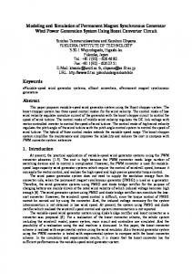
VI. APPLICATION OF PROPOSED METHOD TO MACHINE DESIGN A. Flux Density in the Stator Teeth The flux density calculated from MEC was compared to that computed using FEM. One pole in FEM had 4092 elements and 8138 nodes, whereas there are only 144 elements (88 saturating and 56 nonsaturating) and 72 nodes in a pole pair of the machine for MEC. Fig. 7 shows the comparison of space and time variation of the flux density at no load. Fig. 7(a) shows the flux density on an arc path in the stator teeth at an instant of time and Fig. 7(b) shows the time variation of the flux density in a stator tooth. Similar comparison is shown for rated machine current
in Fig. 8. Flux density calculated by the proposed method in the stator teeth agrees with that computed by FEM.
B. Iron and Magnet Losses The proposed method was used in two variations of a machine design to calculate iron and magnet losses. The baseline machine has the geometry of Figs. 1 and 3, while the modified one has 1.5 times thicker magnets in its interior layer. All other parameters were the same. The results are compared to those of FEM in Table II. The losses were calculated at three different load current levels: no load, half load, and full load. MEC gives losses between 6% and 12% lower than those calculated by FEM at all load conditions, in both machines. Errors are in the same direction. Losses of the modified machine calculated by FEM are higher at no load, and lower at half and full load than those of the baseline machine. This relation is similar to the results obtained from the proposed method using MEC model. An alternate and more accurate method to calculate the iron and magnet
TARIQ et al.: IRON AND MAGNET LOSSES AND TORQUE CALCULATION OF IPMSMs USING MAGNETIC EQUIVALENT CIRCUIT
4079
TABLE III TORQUE COMPARISON RATED CURRENT CALCULATED USING FEM AND MEC
the air gap were calculated for all overlapping elements at each time step. Arkkio’s method uses (11) to calculate the instantaneous torque of the machine
(11) where is the stack length of the machine, is the mean air gap radius, and is the overlapping angle of stator and rotor elements. Table III compares average torque of the two machines discussed earlier in this section. The torque was calculated by FEM and MEC at rated current applied in the quadrature axis of the machine. The error is within 12% in the same direction as that of the losses in Table II, which shows that torque calculation results are also consistent with those of iron and magnet losses. Losses and torque calculation took 195 s using the proposed method, whereas FEM spent about 3 h. VII. CONCLUSION
Fig. 8. Comparison of space and time variation of flux density in stator teeth at full load. (a) Space variation in teeth. (b) Time variation a tooth.
TABLE II COMPARISON OF IRON AND MAGNET LOSSES CALCULATED USING FEM AND MEC
losses from the flux density of each reluctance of the MEC using piece wise linear model is discussed in [5] and [6]. C. Developed Torque The developed torque of the machine was calculated by Arkkio’s method, a variant of Maxwell stress tensor method [30], [31]. From the MSP at each node of the MEC, normal and tangential components of the flux density in
A numerical method based on a MEC model was developed for the calculation of iron and magnet losses and torque of IPMSMs. Starting from the basic geometry, winding configuration and input currents of the machine, a system of nonlinear equations was derived and solved in the time domain for the MSP of the nodes. The system of equations is nonlinear, and it was solved iteratively at each time step, using the – data points of the iron core material. The flux density in each element was calculated from the MSP of the nodes, and this led to the calculation of the iron and magnet losses of the machine. The results of the proposed method were compared to those obtained using FEM. The proposed method gave lower iron and magnet losses and torque than those calculated by FEM when it was applied to two different machines. Although this difference is significant, the results of the loss calculations for these designs show similar trends as those obtained using FEM. The proposed method requires much less time for calculation of iron losses and torque than FEM. Therefore, this method can be useful for early sizing and efficiency comparison of several machine designs in reduced time. The MEC model of a machine can be developed easily from its geometry, thus shortening the total computation time. REFERENCES [1] S. Williamson, M. Lukic, and A. Emadi, “Comprehensive drive train efficiency analysis of hybrid electric and fuel cell vehicles based on motor-controller efficiency modeling,” IEEE Trans. Power Electron., vol. 21, no. 3, pp. 730–740, May 2006. [2] C. Mi, G. Slemon, and R. Bonert, “Modeling of iron losses of permanent-magnet synchronous motors,” IEEE Trans. Ind. Appl., vol. 39, no. 3, pp. 734–742, May–Jun. 2003.
4080
[3] W. Roshen, “Iron loss model for permanent-magnet synchronous motors,” IEEE Trans. Magn., vol. 43, no. 8, pp. 3428–3434, Aug. 2007. [4] E. Dlala, “A simplified iron loss model for laminated magnetic cores,” IEEE Trans. Magn., vol. 44, no. 11, pp. 3169–3172, Nov. 2008. [5] W. Roshen, “Magnetic losses for non-sinusoidal waveforms found in AC motors,” IEEE Trans. Power Electron., vol. 21, no. 4, pp. 1138–1141, Jul. 2006. [6] W. A. Roshen, “A practical, accurate and very general core loss model for nonsinusoidal waveforms,” IEEE Trans. Power Electron., vol. 22, no. 1, pp. 30–40, Jan. 2007. [7] K. Yamazaki and Y. Seto, “Iron loss analysis of interior permanent-magnet synchronous motors-variation of main loss factors due to driving condition,” IEEE Trans. Ind. Appl., vol. 42, no. 4, pp. 1045–1052, Jul.–Aug. 2006. [8] J.-H. Seo, T.-K. Chung, C.-G. Lee, S.-Y. Jung, and H.-K. Jung, “Harmonic iron loss analysis of electrical machines for high-speed operation considering driving condition,” IEEE Trans. Magn., vol. 45, no. 10, pp. 4656–4659, Oct. 2009. [9] A. Belahcen and A. Arkkio, “Comprehensive dynamic loss model of electrical steel applied to FE simulation of electrical machines,” IEEE Trans. Magn., vol. 44, no. 6, pp. 886–889, Jun. 2008. [10] J. R. Hendershot, Jr. and T. J. E. Miller, Design of Brushless Permanent Magnet Motors. Oxford, U.K.: Magna Physics Publishing and Oxford University Press, 1994. [11] T. J. E. Miller, Combined User’s Manual for Windows Version of SPEED Software. Glasgow, U.K., SPEED Laboratory, University of Glasgow, 2007. [12] V. Ostovic, Dynamics of Saturated Electric Machines. New York: Springer-Verlag, 1989. [13] J. K. Kim, S. W. Joo, S. C. Hahn, J. P. Hong, D. H. Kang, and D. H. Koo, “Static characteristics of linear BLDC motor using equivalent magnetic circuit and finite element method,” IEEE Trans. Magn., vol. 40, no. 2, pp. 742–745, Mar. 2004. [14] K. Nakamura, S. Fujio, and O. Ichinokura, “A method for calculating iron loss of an SR motor based on reluctance network analysis and comparison of symmetric and asymmetric excitation,” IEEE Trans. Magn., vol. 42, no. 10, pp. 3440–3442, Oct. 2006. [15] J. Perho, “Reluctance netwrork for analysing induction machines,” Acta Polytechnica Scandinavica, Elect. Engg. Series No. 110, PhD Dissertation, vol. 1, pp. 1–147, Dec. 2002. [16] S. D. Sudhoff, B. T. Kuhn, K. A. Corzine, and B. T. Branecky, “Magnetic equivalent circuit modeling of induction motors,” IEEE Trans. Energy Convers., vol. 22, no. 2, pp. 259–270, Jun. 2007. [17] M. Moallem and G. E. Dawson, “An improved magnetic equivalent circuit method for predicting the characteristics of highly saturated electromagnetic devices,” IEEE Trans. Magn., vol. 34, no. 5, pp. 3632–3635, Sep. 1998. [18] M. A. Batdorff and J. H. Lumkes, “High-fidelity magnetic equivalent circuit model for an axisymmetric electromagnetic actuator,” IEEE Trans. Magn., vol. 45, no. 8, pp. 3064–3072, Aug. 2009. [19] M. Amrhein and P. T. Krein, “Force calculation in 3-D magnetic equivalent circuit networks with a Maxwell stress tensor,” IEEE Trans. Energy Convers., vol. 24, no. 3, pp. 587–593, Sep. 2009. [20] M. Amrhein and P. T. Krein, “3-D magnetic equivalent circuit framework for modeling electromechanical devices,” IEEE Trans. Energy Convers., vol. 24, no. 2, pp. 397–405, Jun. 2009. [21] H. W. Derbas, J. M. Williams, A. Koenig, and S. D. Pekarek, “A comparison of nodal- and mesh-based magnetic equivalent circuit models,” IEEE Trans. Energy Convers., vol. 24, no. 2, pp. 388–396, Jun. 2009. [22] Z. Zhu, Y. Pang, D. Howe, S. Iwasaki, R. Deodhar, and A. Pride, “Analysis of electromagnetic performance of flux-switching permanent-magnet machines by nonlinear adaptive lumped parameter magnetic circuit model,” IEEE Trans. Magn., vol. 41, no. 11, pp. 4277–4287, Nov. 2005. [23] W. Soong, D. Staton, and T. Miller, “Validation of lumped-circuit and finite-element modelling of axially-laminated brushless motors,” in Sixth Int. Conf. Electrical Machines and Drives, Sep. 1993, pp. 85–90.
IEEE TRANSACTIONS ON MAGNETICS, VOL. 46, NO. 12, DECEMBER 2010
[24] E. Lovelace, T. Jahns, and J. Lang, “A saturating lumped-parameter model for an interior PM synchronous machine,” IEEE Trans. Ind. Appl., vol. 38, no. 3, pp. 645–650, May/Jun. 2002. [25] L. Zhu, S. Z. Jiang, Z. Q. Zhu, and C. C. Chan, “Analytical modeling of open-circuit air-gap field distributions in multisegment and multilayer interior permanent-magnet machines,” IEEE Trans. Magn., vol. 45, no. 8, pp. 3121–3130, Aug. 2009. [26] A. Tariq, C. Nino, and E. Strangas, “A novel numerical method for the calculation of iron and magnet losses of IPMSMs,” in IEEE Int. Electric Machines and Drives Conf. (IEMDC ’09), May 2009, pp. 1605–1611. [27] D. S. Watkins, Fundamentals of Matrix Computations. New York: Wiley, 2002. [28] “Flux 10.3 2D Application User Guide Volume 4, Solving and Results Post Processing,” CEDRAT GROUP, 2007. [29] X. Wang, J. Li, and P. Song, “The calculation of eddy current losses density distribution in the permanent magnet of PMSM,” in Proc. 2005 Asia Pacific Microwave Conf. (APMC), Dec. 2005, vol. 3. [30] A. Arkkio, “Time-stepping finite element analysis of induction motors,” in Int. Conf. Electrical Machines, ICEM’ 88, Sep. 1988. [31] N. Sadowski, Y. Lefevre, M. Lajoie-Mazenc, and J. Cros, “Finite element torque calculation in electrical machines while considering the movement,” IEEE Trans. Magn., vol. 28, no. 2, pp. 1410–1413, Mar. 1992.
Abdul Rehman Tariq (S’08) received the B.S. degree from the University of Engineering and Technology, Lahore, Pakistan, in 1993 and the M.S. degree from Michigan State University, East Lansing, MI, in 2002 , both in electrical engineering. He is working toward the Ph.D. degree in the Electrical Machines and Drives Laboratory, Electrical and Computer Engineering Department, Michigan State University. He was with Pakistan Steel, Karachi, Pakistan (1993–1995) and Advanced Engineering Research Organization, Hasan Abdal, Pakistan (1995–2006). His industrial experience encompasses the control of high-power dc drives and system engineering of integrated electromechanical systems. His research interests include efficient design and control of high power electrical machines and finite-element methods for electromagnetic systems.
Carlos E. Nino-Baron (S’06) received the B.S. degree from Universidad Industrial de Santander, Colombia, in 2002 and the M.S. degree from the University of Puerto Rico, Mayagüez, PR, in 2006, both in electrical engineering. He is currently working toward the Ph.D. degree in electrical engineering in the Electrical Machines and Drives Laboratory of the Electrical and Computer Engineering Department of Michigan State University, East Lansing, MI. His research interests are in the areas of design and control of a PMAC machines and drives for hybrid systems.
Elias G. Strangas (M’80) received the Dipl. Eng. degree in electrical engineering from the National Technical University of Greece, Athens, Greece, in 1975 and the Ph.D. degree from the University of Pittsburgh, Pittsburgh, PA, in 1980. He was with Schneider Electric (ELVIM), Athens, from 1981 to 1983 and the University of Missouri, Rolla, from 1983 to 1986. Since 1986, he has been with the Department of Electrical and Computer Engineering, Michigan State University, East Lansing, MI, where he heads the Electrical Machines and Drives Laboratory. His research interests include the design and control of electrical machines and drives, finite-element methods for electromagnetics, and fault prognosis and mitigation of electrical drive systems.