IEEE TRANSACTIONS ON ANTENNAS AND PROPAGATION, VOL. 56, NO. 11, NOVEMBER 2008
3411
Isolation Enhancement Between Two Closely Packed Antennas Angus C. K. Mak, Corbett R. Rowell, and Ross D. Murch
Abstract—This paper introduces a coupling element to enhance the isolation between two closely packed antennas operating at the same frequency band. The proposed structure consists of two antenna elements and a coupling element which is located in between the two antenna elements. The idea is to use field cancellation to enhance isolation by putting a coupling element which artificially creates an additional coupling path between the antenna elements. To validate the idea, a design for a USB dongle MIMO antenna for the 2.4 GHz WLAN Band is presented. In this design, the antenna elements are etched on a compact low- cost FR4 PCB board with 3 . According to our measurement dimensions of 20 40 1.6 results, we can achieve more than 30 dB isolation between the antenna elements even though the two parallel individual planar inverted F antenna (PIFA) in the design share a solid ground plane with inter-antenna spacing (Center to Center) of less than or edge to edge separations of just 3.6 mm (0.0294 ). Both simulation and measurement results are used to confirm the antenna isolation and performance. The method can also be applied to different types of antennas such as non-planar antennas. Parametric studies and current distribution for the design are also included to show how to tune the structure and control the isolation.
mm
0 095
Index Terms—Diversity antennas, multiple input and multiple output (MIMO), mutual coupling, planar inverted F antenna (PIFA), wireless communications.
I. INTRODUCTION
T
HE isolation between antennas is a critical parameter in many practical applications such as antenna arrays, diversity antennas and also multiple input multiple output (MIMO) communication systems. Of these applications, MIMO systems have attracted significant attention as they have the potential to achieve significant increases in wireless channel capacity without the need for additional transmit power or spectrum [1], [2]. One important requirement for MIMO antenna systems is the requirement for good isolation between antenna elements. In addition, for application in portable devices very small form factors are an important requirement and therefore good isolation between antennas with closely packed antenna elements is necessary. The design of closely packed MIMO antennas with good isolation is difficult to achieve and for an infinite array of antennas there are fundamental limits to the maximum isolation Manuscript received October 23, 2007; revised July 06, 2008. Current version published November 14, 2008. A. C. K. Mak and C. R. Rowell are with the Hong Kong Applied Science and Technology Research Institute, Shatin, New Territories, Hong Kong (e-mail:
[email protected]). R. D. Murch is with the Department of and Electronic and Computer Engineering, The Hong Kong University of Science and Technology, Clear Water Bay, Kowloon, Hong Kong. Digital Object Identifier 10.1109/TAP.2008.2005460
that can be achieved [3]. For planar inverted F antennas (PIFAs) oriented either collinear, orthogonal or parallel above a single ground plane with air substrate, it is often stated that the inter-element spacing should be at least greater than half of the free space wavelength in order to achieve approximately 20 dB isolation or more [4]–[6]. However for small numbers of closely packed antennas (usually 2–3 antennas) researchers have found that there are various methods that can be utilized to improve antenna isolation. For example mushroom-like EBG structures can suppress the surface wave between antenna elements [7]–[9], and thus reduce the mutual coupling between antenna elements. However, a number of mushroom-like structures are needed to be put under the antenna elements and this occupies a large area. Also, the defected ground structure (DGS) [10], [11] or a simple ground plane modification [12] has also been shown to provide a band-stop effect by suppressing the ground current flowing between antenna elements. It has been used for suppressing harmonics, cross polarization, and for increasing isolation of antenna [13], [14]. However, it creates difficulties for RF circuits to feed the antenna elements when the solid ground plane PCB is modified or removed. In addition, a compact integrated diversity antenna with two feed ports has been proposed in [15], [16]. Since they are based on patch antennas, the size may not be suitable in very small form factors. In [17], slot-cutting on the antenna elements to improve isolation is introduced, but there is no general solution to provide isolation. In [21], they put a two-port network on the input port of antenna elements. The two-port network comprises two stages of matching networks and a decoupling network. The isolation is enhanced by optimizing those networks such that S11 is minimized or S11 is in quadrature with S12. In [22]–[24], a suspended neutralization strip is inserted and physically connected to the antenna elements for improving isolation. This line samples a certain amount of the signal on one antenna element and delivers to the other antenna element in order to cancel out the existing mutual coupling. In this paper, we describe an alternative method for field cancellation between a pair of closely-packed antenna elements within a very small form factor. Instead of putting a suspended strip line that is physically connected to the antenna elements [22]–[24], we add a coupling element between the antenna elements in order to artificially create an additional coupling path for enhancing the isolation. This coupling element is not physically connected to the antenna elements and it is flexible both for controlling the frequency band of isolation, maximum isolation and the bandwidth of the transmission reduction between antenna elements. This additional coupling path is used to cancel out the original coupling and hence enhance the isolation between antenna elements. The size of the coupling element is
0018-926X/$25.00 © 2008 IEEE
3412
IEEE TRANSACTIONS ON ANTENNAS AND PROPAGATION, VOL. 56, NO. 11, NOVEMBER 2008
Fig. 1. Proposed isolation method. (a) Coupling between two closely spaced dipole antennas. (b) Coupling between two dipoles and an additional third element.
compact and flexible and the solid ground plane of the device does not need to be modified. To demonstrate the idea, a two antenna element MIMO USB dongle for use in 2.4 GHz WLAN 802.11 n is proposed. The whole structure consists of two antenna elements, one coupling element located between the two antenna elements. To have a more practical design, those elements are etched with a compact size on low cost FR4 PCB . FR4 is a common board with dimensions 20 40 1.6 material and easy for manufacture. It is found that the design can achieve more than 30 dB isolation with inter-antenna spacing (3.6 mm) demonstrating that (edge to edge) of less than significant improvement in isolation between antenna elements can be obtained. In Section II, the basic idea of utilizing the coupling element for enhancing isolation or equivalently compensating the effect of mutual coupling is described. We introduce the proposed structure for the 2 element MIMO USB dongle antenna in Section III and we also demonstrate its effectiveness by comparing more standard approaches. In Section IV, parametric studies are provided and they show how to tune the frequency band of isolation, maximum isolation and the bandwidth of the transmission reduction between antenna elements while in Section V a brief discussion of extensions to non-planar structures, multi-frequency bands and an increase in the number of antenna elements are also given to illustrate how the design concept can be extended. Finally, in Section VI, a conclusion of the proposed isolation method is presented.
II. PROPOSED ISOLATION METHOD To illustrate our isolation technique we first describe it using a simplified dipole model as shown in Fig. 1(a). As can be observed two dipoles are arranged close together and parallel to each other and it is assumed that the conductor diameter of the dipoles are small and the electrical length of each dipole is around half-wavelength. Port A is driven by a current source and Port B of dipole B is loaded with 50 ohms.
Assume a sinusoidal signal is fed into dipole A and the current flows in the same direction on dipole A. Since dipole B is put very close to dipole A, the strong coupled current on dipole B is approximately 180 degree out as shown of phase with the excited current on dipole in Fig. 1(a). In addition, the coupled current is directly proportional to excited current . Possible ways to reduce the coupling current are to arrange the two dipoles to be orthogonal to each other or to separate them further apart. However, those arrangements occupy a large area. Our proposed method is to introduce one more coupling path and this coupling path creates another coupled current with pre-determined magnitude and phase in order to cancel out the original coupling. The simplified diagram for the proposed method is shown in Fig. 1(b) where we create one more coupling element C which is put between the two dipoles. The total electrical length of the coupling element is around half wavelength. The capacitive loading on the top is used to minimize its length and controls the magnitude of coupling between the two dipoles. With this additional element there are two coupling paths. One is the original coupling path directly between dipoles while the other path that we create, is through the additional element. In this case the coupling starts from dipole A, through to the coupling element C, which, in turn, couples to dipole B. The direct coupling between elements A and B is similar to the previous case in Fig. 1(a). In Fig. 1(b) we denote the coupled current on dipole and it is approximately 180 degree out of B as on dipole A and the phase with the excited current overall magnitude depends on the coupling factor which we denote as . For the other coupling path we create, it occurs through the middle portion of the dipoles and is provided by coupling elon dipole B ement C. This coupled current is approximately in phase with the excited current on dipole . The reason is that the coupling element C introduces an additional 180 degree phase shift to this coupling path. So, the resultant coupled current on this path has approximately
MAK et al.: ISOLATION ENHANCEMENT BETWEEN TWO CLOSELY PACKED ANTENNAS
Fig. 2. Simulation model for proposed isolation method.
Fig. 4. Dimensions of proposed structure.
Fig. 3. S11 and S21 for dipoles with proposed isolation method.
no overall phase shift. If is the coupling factor in this path and is adjusted properly, the two coupled currents can be canof the second path celled out by controlling the magnitude so that the overall resultant coupled current is zero and this can be written as
(1) and then this also implies that . By using this method, the isolation can be improved drastically by designing an appropriate coupling element. If we write
3413
The addition of the coupling element C will also reduce the current in the original dipole A, by a similar coupling process, and therefore this will also affect the self-impedance of the anis not tennas. However, as long as the cancellation coupling too large, this effect can be handled by adjusting the antenna matching appropriately. To further illuminate and also help verify the idea, we have included a simulation based on the structure in Fig. 1(b). The detailed dimensions are shown in Fig. 2 where the additional coupling element C is twisted by 90 degrees so it can fit between the two closely spaced dipoles A and B. The thickness of the two identical dipoles and coupling element in the model are 0.1 mm and the dipoles are operating at 2.4 GHz band. The model is simulated by CST Microwave Studio 2006 B, [18] and the simulation result for return loss (Magnitude S11) and isolation (Magnitude of S21) are shown in Fig. 3. As the two dipoles are symmetrical, only S11 and S21 results are shown here. In Fig. 3, we can see that without the coupling element, peak isolation is around 7 dB at resonance while with the proposed method a peak isolation of around 14 dB is achieved when the two dipoles are closely spaced at 20 mm. It is also noted that the level and the position of the peak isolation can be controlled and they will be discussed in greater detail in Sections III–V. Also, the even with the additional coupling return loss is around element. III. IMPLEMENTATION OF TWO-CHANNEL USB DONGLE ANTENNA DESIGN A. A Two-Channel USB Dongle Antenna Design Utilizing the proposed design method as described in the previous section, a practical USB Dongle with 2 antennas operating
3414
IEEE TRANSACTIONS ON ANTENNAS AND PROPAGATION, VOL. 56, NO. 11, NOVEMBER 2008
Fig. 6. Proposed structure—gain and efficiency. Fig. 5. Proposed structure—return loss and isolation.
at the same frequency has been designed. This design can be used for WLAN with MIMO under the proposed 802.11n standard operating at 2.4 GHz. The overall size has to be small, as it is for a USB dongle, while at the same time maintaining good isolation between the antennas and our target size is approxi. mately 20 40 1.6 The details of our proposed USB WLAN Dongle with 2 antennas are shown in Fig. 4 where the dash-line shows the FR4 PCB substrate and the copper is shown in solid grey color. It can be seen that two identical PIFA [6], [19] antenna elements are integrated on a low cost FR4 substrate with a PCB thickness of 1.6 mm and relative permittivity 4.3. Their inter-antenna (11.6 mm) or spacing (center-to-center) is less than edge-to-edge separation is just 3.6 mm (0.0294 ). The PIFA are located on the top left hand side and right hand side of the PCB respectively and the resonant length is approximately a quarter wavelength. The coupling element is introduced for enhancing isolation and is located between the two PIFA antenna elements and is symmetrical above the centre of the overall antenna configuration. It is formed by adding two symmetrical arms and the shape of each arm roughly approximates an inverted L. The top middle and bottom of the PCB is reserved as a solid ground plane so that RF and digital circuitry can be placed there for practical use and allows the RF circuit to feed the antenna elements. The length of the coupling element comprises a common vertical path located between the two PIFA antennas and two separated horizontal paths located on the top of the two PIFA antennas. The common vertical path is mainly to provide the coupling mechanism to increase the isolation between the PIFA antenna elements and it couples the field with correct magnitude and phase among the PIFA antenna elements to increase isolation. The horizontal paths are for controlling the total electrical length which should resonate at the desired band at around 2.45 GHz. It consists of a meander line and capacitive loading in order to shorten its length. The resonant frequency of the coupling element is approximately given by (2)
where is the speed of light, is the vertical length of the coupling element located between the PIFA antenna elements and is the total length of the coupling element located on the top of either left or right hand side of the PIFA elements and is the extension length due to the capacitive or inductive loading effect. The proposed antenna structure is then simulated using CST [18] and a prototype is built. The return loss and isolation for both the simulation and measurement are shown in Fig. 5. As the two PIFA antenna elements are symmetrical, only S11 and S21 results are shown here. From the measurement results, it can be observed that the design for the USB WLAN Dongle with 2 antennas is realized and it covers the WLAN Band (2.4 GHz–2.48 GHz) with maximum 30 dB isolation as shown in Fig. 5. Although there is a slight undulation of the results and discrepancy between measured and simulated results, the points of our interest such as the frequency band and the deepest point for isolation are clearly shown. We believe the slight undulation is due to coupling between cables and the slight discrepancy is due to coupling between cables and the inaccurate PCB’s dielectric constant model. return According to the measurement result for the loss specification, it shows that the antenna can cover WLAN (802.11b, g or n) (2.4 GHz–.2.48 GHz). To further confirm the performance of the design, the gain and efficiency measurement was also carried out using a Satimo-StarLab near-field measurement system [20] in order to verify the actual gain and efficiency performance and is shown in Fig. 6. Since we are concerned with dual port antennas, when we measure one of the antenna elements for either efficiency or antenna pattern, the other antenna port is loaded with 50 ohms. From this result obtained thereby, the peak efficiency is up to 60% and the peak gain is 2 dBi. These clearly demonstrate the antenna can cover the WLAN 2.45 GHz band with 50% or greater efficiency. In addition, total efficiency due to mutual coupling can be calculated by the following equation.
(3)
MAK et al.: ISOLATION ENHANCEMENT BETWEEN TWO CLOSELY PACKED ANTENNAS
3415
Fig. 7. Proposed structure—antenna pattern.
Fig. 8. Antenna dimensions for different configurations.
where
is the total efficiency due to mutual coupling and is the radiation efficiency. From (3), the loss for our proposed antenna with 30 dB isolation due to mutual coupling is not significant and it is only 1%. The measured and simulated antenna patterns for exciting port 1 (left Port) at 2.4 GHz, 2.45 GHz, and 2.48 GHz are shown in Fig. 7. The differences can be attributed to the feeding cable influences on the radiation patterns. From the Theta 90 pattern illustrated in Fig. 7, the directive beam is radiating toward the direction between XY axes when the left port is excited. Similarly, the directive beam is radiating toward the direction beaxes when the right port is driven. This gives an tween advantage for MIMO application as two uncorrelated antenna patterns are favorable for MIMO applications.
Fig. 9. Different antenna configurations—return loss and isolation.
B. Comparison to Other USB WLAN Dongle Designs To provide comparisons, two other USB dongle antenna configurations are considered in Section III-C and D. These are (a) antenna without coupling element, (b) antenna with separated
ground plane. With these configurations we slightly adjusted the antenna length so the resonant frequency is fine-tuned to the correct range but the overall PIFA design remains the same.
3416
IEEE TRANSACTIONS ON ANTENNAS AND PROPAGATION, VOL. 56, NO. 11, NOVEMBER 2008
Fig. 10. Different antenna configurations—antenna pattern.
C. Antennas Without Coupling Element To verify the advantage of implementing the coupling element, the USB WLAN dongle configuration without coupling element was designed and the dimensions are the same as the first design except that this design does not contain the coupling element. The detail dimensions are shown in Fig. 8(a). and the copper is shown in solid grey color. The design has been simulated and built. The simulated and measurement result both for return loss and isolation are shown in Fig. 9(a). From the meareturn-loss bandsurement result, the isolation and the width are 6.12 dB and 115 MHz respectively. The simulated and measurement antenna pattern is shown in Fig. 10(a). In addition, the gain and efficiency measurement is carried out and shown in Fig. 11(a) and (b) respectively. From the results, the peak isolation is only around 6 dB and would not be sufficient for good MIMO operation and is much worse than the design using coupling elements where the isolation is over 30 dB. Besides this, both the measured peak efficiency (40%) and antenna gain (0 dBi) is lower than the one using coupling element, which are 60%, 2 dBi. For the 6 dB isolation, the efficiency reduction due to this poor isolation can be calculated from (3). It is around a 25% reduction for efficiency due to the mutual coupling. In Fig. 11(b), the measurement result for efficiency between the antennas with coupling element and the one without coupling element are also very close to this value. D. Antenna With Separated Ground Plane A USB dongle antennas with separated ground plane has also been designed. Although this may not be feasible for use in a
product as the electronic and RF circuitry need to have the same solid ground plane to feed the antenna elements, it is worthwhile to demonstrate this case with two separated grounds to compare with our proposed structure. A long slot 2 mm 40 mm is cut out through the ground plane and the detail dimensions are shown in Fig. 8(b) and the copper is shown in solid grey color. The design has been simulated and built. The simulated and measurement results both for return loss and isolation are shown in Fig. 9(b). From the measurement result, the isolation and the 6 dB bandwidth are 6.3 dB and 130 MHz respectively. The simulated and measurement antenna pattern are shown in Fig. 10(c). In addition, the gain and efficiency measurement is carried out and shown in Fig. 11(a) and (b) respectively. From the measurement results, the isolation is only around 6 dB and it is again worse than that of our proposed structure (30 dB). Besides this, both the measured efficiency (35%) and Peak antenna gain (1 dBi) are lower than those of the proposed structure, which are 60% and 2 dBi. The radiation pattern is also distorted and the directivity is reduced. The maximum gain on azimuth revealed in Fig. 10(b). The reason is that plane is only the small ground planes are radiating as well and this distorts the radiation pattern. IV. PARAMETRIC COUPLING ELEMENT STUDIES To further demonstrate the operation of the proposed structure described in Section III-A, we have performed some parametric studies and they explain how to tune the frequency band of isolation, maximum isolation and the bandwidth of the transmission reduction between antenna elements. We also present the surface current distribution on the element.
MAK et al.: ISOLATION ENHANCEMENT BETWEEN TWO CLOSELY PACKED ANTENNAS
3417
Fig. 12. Isolation versus two parameters (CL, CW).
Fig. 11. Different antenna configurations—gain and efficiency. Fig. 13. Isolation versus coupling width with optimal coupling.
A. Parametric Studies From the result of the proposed antenna with coupling element, it can be seen that the coupling element structure has a very good impact on improving isolation. To understand the design of the proposed structure and how to tune the frequency band of isolation, maximum isolation and the bandwidth of the transmission reduction between antenna elements, we have performed parametric studies of the coupling element. The study is based on the geometry given in Fig. 4. Referring to Fig. 4, the coupling element has two key parameters which we refer to as the coupling length (CL) and the coupling width (CW) as labeled on Fig. 4. We simulate the proposed structure in Fig. 4. and vary these two parameters (CW, CL) in order to understand how to tune the structure. For the studies on the effect of CW, firstly we fix the value of and vary the CW from 0.4 mm coupling length to 0.8 mm. In Fig. 12, we can observe that the position of the maximum isolation shifts to a higher frequency when the CW increases. (See the curves , 2/0.2, 2/0.6, 2/0.8 in Fig. 12). Secondly we fix the value of CW
and vary the CW from 1.5 mm to 2.5 mm. In Fig. 12, we can observe that the position of the maximum isolation shifts to lower frequency when the CL increases (see the curves , 1.75/0.4, 2.25/0.4, 2.5/0.4). From the result, we can notice that both the CL and CW have a big effect on the position of maximum isolation. Narrower CW and longer CL shift the maximum isolation to a lower frequency range. It is thought that they control the resonant length of the coupling element and shifts the position of maximum isolation in the frequency range. In addition, the parameter CW does not only have an effect on controlling the position of maximum isolation along the frequency range, it also plays an important role on the coupling level for canceling the mutual coupling. To verify this, we vary the parameter of CW from 0.2 mm to 1.8 mm and also tune the parameter of CL such that the position of maximum isolation point remains at the center frequency of operating band (i.e., 2.45 GHz). As depicted in Fig. 13. the level of maximum isolation becomes deeper when we reduce the CW. The reason is
3418
IEEE TRANSACTIONS ON ANTENNAS AND PROPAGATION, VOL. 56, NO. 11, NOVEMBER 2008
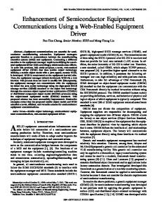
Fig. 14. Current distribution (a) without and (b) with coupling element.
that the narrower CW increases the field strength of the coupling element and which cancels out the mutual coupling between antenna elements and thus enhances the isolation. In addition to controlling the level of maximum isolation, the CW can also tune the bandwidth of the transmission reduction be,a tween antenna elements. In Fig. 13, when minimum isolation of at least 15 dB can be achieved across the (2.4 GHz–2.5 GHz) WLAN operating band. With this isolation, the efficiency degradation across the band (2.4 GHz–2.5 GHz) is only 1.4% according to (3). 1) Surface Current Distribution: To better understand how the coupling element improves isolation, an investigation of the surface current is also provided. Fig. 14(a) displays the simulations without coupling element. In this case, we excited the antenna element (PIFA A) on the left hand side and plot the surface current on the entire structure. In this arrangement, there is a strong current induced on the antenna element (PIFA B) on the right hand side. This induced current is 180 degree out of phase with the antenna element A (PIFA A) as we mentioned in Section II. For the case with coupling element as in Fig. 14(b), we excited antenna element (PIFA A) on the left hand side as with the previous case. We can see that the current induced on the antenna element (PIFA B) on the right hand side is much reduced. The reason is that the antenna element on the left (PIFA A) induces a reverse current on the vertical part of the coupling element. In turn it induces the co-phase current on the antenna element on the right (PIFA B) such that it cancels out the reverse current caused by coupling. We can see on Fig. 14(b) illustrates that there is a reverse current on the vertical part of the coupling element and a co-phase current on the antenna element the right (PIFA B). V. DISCUSSION The proposed isolation method described in the previous sections is applied to planar antennas structures. However, the principle can further be enhanced to the antennas with non-planar structure. Both the antenna elements and coupling element can be non-planar structures provided that the opposed current (i.e., opposed to the current due to mutual coupling) can be coupled and appropriately weighted between antenna elements through the coupling element. In addition, the proposed method can also be utilized for dual band antennas (i.e., 2.4 GHz/5.8 GHz WLAN) or multi-bands.
The coupling element can be designed to improve one or several bands. The choice depends on the isolation requirements for each band. In multi-band design, the lower band is usually the most critical one as the separation between antenna elements in terms of electrical length is relatively smaller than the higher bands. One practical approach is to improve the lower bands only if the isolation of higher bands is acceptable for the application. Of course, the coupling element for multi-bands can also be constructed using the same design method. For example, the dual band coupling design can be similar to the structure illustrated in Fig. 4 except that one more symmetrical horizontal path can be added to create one more resonant. For more bands, the design mainly depends on the complexity of the coupling element and the space available for the whole structure. The idea can also be extended to a system which contains more than two antenna elements. For example, in the case of a system containing three antenna elements, three coupling elements can be used. The three antenna elements (Antenna A, Antenna B, Antenna C) will be arranged in a circular way and oriented 120 degree with one another. The three coupling elements (1, 2, 3) can be put in between each pair of antenna elements (i.e., coupling element 1 between A and B, 2 between B and C). By a proper design, the coupling element can provide the proper magnitude and phase coupling for improving isolation. However, with more elements the isolation reduction will not be so effective and will reach fundamental limits in the infinite element case described in [3] VI. CONCLUSION In this paper, a coupling element to enhance isolation for closely packed antennas operating at the same frequency is proposed. We artificially create an additional coupling path by utilizing a coupling element to neutralize the coupling between the antenna elements. A simplified dipole model is introduced to demonstrate the proposed concept with the coupling element for improving isolation. A practical, compact and low-cost USB WLAN MIMO dongle with 2 antennas for use in 2.4 GHz WLAN 802.11n, is designed and demonstrated. In the design, the antenna elements with coupling element are located on compact PCB, with dimensions 20 40 1.6 mm and etched on low cost FR4 board. The MIMO USB dongle antenna was simulated and prototyped for verification. It can operate in 802.11b WLAN band for MIMO application with maximum 30 dB isolation, 2 dBi peak gain and 60% peak efficiency with (11.6 mm) their spacing (Center to Center) less than or edge to edge separations just 3.6 mm (0.0294 ). Various parameters are evaluated to see how they can be used to tune the frequency band of the maximum isolation, peak isolation and the bandwidth of the transmission reduction. REFERENCES [1] G. J. Foschini, “Layered space-time architecture for wireless communication in a fading environment when using multi-element antennas,” Bell Labs Tech J., vol. 1, no. 2, pp. 41–59, 1996. [2] J. W. Wallace, M. A. Jensen, A. L. Swindlehurst, and B. D. Jeffs, “Experimental characterization of the MIMO wireless channel: Data acquisition and analysis,” IEEE Trans. Wireless Commun., vol. 2, pp. 335–343, Mar. 2003.
MAK et al.: ISOLATION ENHANCEMENT BETWEEN TWO CLOSELY PACKED ANTENNAS
[3] W. K. Kahn, “Ideal efficiency of a radiating element in an infinite array,” IEEE Trans. Antennas Propag., vol. AP-15, no. 4, Jul. 1967. [4] H. Carrasco, H. D. Hristov, R. Feick, and D. Cofre, “Mutual coupling between planar inverted-F antennas,” Microwave Opt. Technol. Lett., vol. 42, no. 3, pp. 224–227, Aug. 2004. [5] T. Taga and K. Tsunekawa, “Performance analysis of a built-in planar inverted F antenna for 800 MHz band portable radio units,” IEEE J. Select Areas Commun., vol. SAC-5, pp. 921–929, Jun. 1987. [6] C. R. Rowell and R. D. Murch, “A capacitively loaded PIFA for compact mobile telephone handsets,” IEEE Trans. Antennas Propag., vol. 45, no. 5, pp. 837–842, May 1997. [7] D. Sievenpiper, L. Zhang, R. F. J. Broas, N. G. Alexopolous, and E. Yablonovitch, “High-impedance electromagnetic surfaces with a forbidden frequency band,” IEEE Microw. Theory Tech., vol. 47, no. 11, pp. 2059–2074, Nov. 1999. [8] F. Yang and Y. Rahmat-Samii, “Microstrip antennas integrated with electromagnetic band-gap (EBG) structures: A low mutual coupling design for array applications,” IEEE Trans. Antennas Propag., vol. 51, no. 10, pp. 2936–2946, Oct. 2003. [9] L. Li, B. Li, H. X. Liu, and C. H. Liang, “Locally resonant cavity cell model for electromagnetic band gap structures,” IEEE Trans. Antennas Propag., vol. 54, no. 1, pp. 90–100, Jan. 2006. [10] D. Ahn, J. S. Park, C. S. Kim, J. Kim, Y. Qian, and T. Itoh, “A design of the low-pass filter using the novel microstrip defected ground structure,” IEEE Microw. Theory Tech., vol. 49, no. 1, pp. 86–93, Jan. 2001. [11] C. Caloz, H. Okabe, T. Iwai, and T. Itoh, “A simple and accurate model for microstrip structures with slotted ground plane,” IEEE Microwave Wireless Comp. Lett., vol. 14, no. 4, pp. 133–135, Apr. 2004. [12] C.-Y. Chiu, C.-H. Cheng, R. D. Murch, and C. R. Rowell, “Reduction of mutual coupling between closely-packed antenna elements,” IEEE Trans. Antennas Propag., vol. 55, no. 6, pp. 1732–1738, Jun. 2007. [13] Y. J. Sung, M. Kim, and Y. S. Kim, “Harmonics reduction with defected ground structure for a microstrip patch antenna,” in IEEE Antennas Wireless Propag. Lett., 2003, vol. 2, pp. 111–113. [14] D. Guha, M. Biswas, and Y. M. M. Antar, “Microstrip patch antenna with defected ground structure for cross polarization suppression,” in IEEE Antennas Wireless Propag. Lett., 2005, vol. 4, pp. 455–458. [15] S. C. K. Ko and R. D. Murch, “Compact integration diversity antenna for wireless communications,” IEEE Trans. Antennas Propag., vol. 49, no. 6, pp. 954–960, Jun. 2001. [16] C. T. Song, C. K. Mak, R. D. Murch, and P. B. Wong, “Compact low cost dual polarized adaptive planar phased array for WLAN,” IEEE Trans. Antennas Propag., vol. 53, pp. 2406–2416, Aug. 2005. [17] R. Corbett, A. Mak, and C. L. Mak, “Isolation between multiband antennas,” in IEEE APS/URSI/AMEREM Int. Symp., Albuquerque, NM, Jul. 2006, pp. 551–551. [18] CST Microwave Studio 2006B by Computer Simulation Technology [Online]. Available: http://www.cst.com [19] G. K. H. Lui and R. D. Murch, “Compact dual frequency PIFA designs using LC resonator,” IEEE Trans. Antennas Propag., vol. 49, pp. 1016–1019, Jul. 2001. [20] Satimo [Online]. Available: http://www.satimo.fr/eng/index.php) [21] S. Dossche, S. Blanch, and J. Romeu, “Optimum antenna matching to minimize signal correlation on a two-port antenna diversity,” Electronics Letters, vol. 40, no. 19, Sep. . [22] A. Diallo, C. Luxey, P. L. Thuc, R. Straraj, and G. Kossiavas, “Enhancement of the isolation between two closely spaced mobile internal antennas by a neutralization effect,” presented at the 22nd Int. Rev. Progr. Appl. Comput. Electromagn. (ACES 2006), Miami, FL, Mar. 12–16, 2006. [23] A. Diallo, C. Luxey, P. L. Thuc, R. Staraj, and G. Kossiavas, “Study and reduction of the mutual coupling between two mobile phone PIFAs operating in the DCS1800 and UMTS bands,” IEEE Trans. Antennas Propag., vol. 54, Nov. 2006. [24] A. Diallo, C. Luxey, P. L. Thuc, R. Staraj, and G. Kossiavas, “ENHANCED diversity antennas for UMTs handsets,” presented at the EuCAP, Nice, France, Nov. 6–10, 2006.
3419
Angus C. K. Mak received the B.Eng. degree (First Class honors) in electronic engineering from Hong Kong Polytechnic University in 1996, the M.Sc. degree from the Chinese University of Hong Kong, in 2004, and the Ph.D. degree from Hong Kong University of Science and Technology, in 2008. In 1996, he started as an RF engineer in an R&D company, Ascalade Communications Inc. (formerly Arkon Networks Inc.) in Canada. He worked on antenna and rf/microwave transceiver designs for various handheld wireless products such as wireless communicator, 900 MHz PDA Digital Phone, 1.89 GHz DECT Phone and 2.4 GHz WLAN Access Point. As RF manager from 1999 to 2002, he headed up the design team, successfully putting a series of Antennas and RF Modules into mass production. (Manufactured 400 K Antennas and RF/Microwave transceivers and per week). At present, he is with the Applied Science and Technology Research Institute, Hong Kong, as RF Manager and specializes in Antenna and RF/microwave circuit designs including 2.4 GHz/ 5 GHz smart antenna design, Multiple RF transceivers design, reconfigurable multi-band mobile antenna design, electrically small antennas, MIMO antenna design and Beam-forming Antenna Array design and so on. He has also published several journal articles and conference papers. He holds one patent focusing on smart antenna design. He also has six more RF or antenna patents being filed in the US. His current research interests lie in the design of reconfigurable antenna, miniaturized antenna, multiple antennas, smart antenna, antenna array, RF /Microwave circuit design, isolation enhancement among antennas, MRI, etc.
Corbett R. Rowell received the B.A. degree in physics from the University of California Santa Cruz, in 1994, and the E.E.E. M.Phil. degree from the Hong Kong University of Science and Technology, in 1996. From 1997 to 1999, he worked as an RF Engineer at Allgon Mobile Communications, Sweden. In 1998, he started his own antenna design company, Integra Antennas Ltd. and sold part of it in 2003 to Molex Inc. From 2001 to 2003, he worked on Wall Street at JP Morgan as a technical expert in venture capital. From 2003 to 2005, he was a Senior Antenna Engineer at Molex Inc., Hong Kong. Currently, he is the R&D Director of RF and Antennas at the Applied Science and Technology Research Institute, Hong Kong. He has published over 10 papers and holds over 20 patents (including patents pending). His research interests are MRI, superconducting antennas, miniature antennas, antenna arrays, active antennas, beam-forming, isolation, and cycling.
Ross D. Murch is a Professor of Electronic and Computer Engineering at the Hong Kong University of Science and Technology. He is also a consultant for industry including the Applied Science and Technology Research Institute (ASTRI) and is also the founding and current Director of the Center for Wireless Information Technology at the Hong Kong University of Science and Technology. In July 2005, he was invited to the School of Engineering Science, Simon Fraser University, Canada, as the David Bensted Fellow and in July 2004 he visited Southampton University, UK as an HKTIIT fellow. His unique expertise lies in his combination of knowledge from both wireless communication systems and electromagnetics. He has contributed both to the design of compact antennas for wireless communications and also physical layer algorithms for enhancing the bit rates of wireless systems with over 190 publications and patents in the area of wireless communications that have attracted over 2500 citations. Prof. Murch is an Area Editor for the IEEE TRANSACTIONS ON WIRELESS COMMUNICATIONS and was the Technical Program Chair for the IEEE Wireless Communications and Networking Conference in 2007 and also the Advanced Wireless Communications Systems Symposium at IEEE International Communications Conference in 2002. He was also a keynote speaker at IEEE GCC 2007 and IEEE WiCOM 2007.