PHYSICS OF PLASMAS 17, 056102 共2010兲
Iterated finite-orbit Monte Carlo simulations with full-wave fields for modeling tokamak ion cyclotron resonance frequency wave heating experimentsa… M. Choi,1,b兲 D. Green,2 W. W. Heidbrink,3 R. Harvey,4 D. Liu,3 V. S. Chan,1 L. A. Berry,2 F. Jaeger,2 L. L. Lao,1 R. I. Pinsker,1 M. Podesta,3 D. N. Smithe,5 J. M. Park,2 P. Bonoli,6 and RF SciDAC and SWIM Team 1
General Atomics, P.O. Box 85608, San Diego, California 92186-5608, USA Oak Ridge National Laboratory, Oak Ridge, Tennessee 37830, USA 3 University of California-Irvine, Irvine, California 92697, USA 4 CompX, P.O. Box 2672, Del Mar, California 92014-5672, USA 5 Tech-X Corporation, Boulder, Colorado 80303, USA 6 Massachusetts Institute of Technology, Cambridge, Massachusetts 02139, USA 2
共Received 23 November 2009; accepted 21 January 2010; published online 23 February 2010兲 The five-dimensional finite-orbit Monte Carlo code ORBIT-RF 关M. Choi et al., Phys. Plasmas 12, 1 共2005兲兴 is successfully coupled with the two-dimensional full-wave code all-orders spectral algorithm 共AORSA兲 关E. F. Jaeger et al., Phys. Plasmas 13, 056101 共2006兲兴 in a self-consistent way to achieve improved predictive modeling for ion cyclotron resonance frequency 共ICRF兲 wave heating experiments in present fusion devices and future ITER 关R. Aymar et al., Nucl. Fusion 41, 1301 共2001兲兴. The ORBIT-RF/AORSA simulations reproduce fast-ion spectra and spatial profiles qualitatively consistent with fast ion D-alpha 关W. W. Heidbrink et al., Plasma Phys. Controlled Fusion 49, 1457 共2007兲兴 spectroscopic data in both DIII-D 关J. L. Luxon, Nucl. Fusion 42, 614 共2002兲兴 and National Spherical Torus Experiment 关M. Ono et al., Nucl. Fusion 41, 1435 共2001兲兴 high harmonic ICRF heating experiments. This work verifies that both finite-orbit width effect of fast-ion due to its drift motion along the torus and iterations between fast-ion distribution and wave fields are important in modeling ICRF heating experiments. © 2010 American Institute of Physics. 关doi:10.1063/1.3314336兴 I. INTRODUCTION
Ion cyclotron resonance frequency 共ICRF兲 wave is one of main auxiliary plasma heating methods in present tokamak experiments and future ITER.1 In particular, the ICRF wave with frequency equivalent to high ion cyclotron harmonic number has been used to heat background thermal electrons and drive noninductively plasma current in the DIII-D 共Ref. 2兲 and National Spherical Torus Experiment 共NSTX兲 共Ref. 3兲 devices. Although primary damping of ICRF wave is expected to occur on thermal electrons, theory predicts that partial damping of ICRF wave may also occur on fast-ions when a large population of fast-ions exists in the form of injected neutral beam ion and fusion born alpha due to k⬜ ⱖ 1 共k⬜ is the perpendicular wave number and is the fast-ion Larmor radius兲, which results in a reduction of current drive efficiency. This theoretical prediction has been observed in both DIII-D4,5 and NSTX6,7 high harmonic ICRF wave heating experiments in neutral beam preheated plasma aimed at full noninductive current drive. Experimental results indicated significant parasitic absorption by injected deuterium beam fast-ion at high harmonics. A first indication is enhanced neutron emission rate measured from neutron detector, increasing by a factor of 2 in DIII-D4,5 and a factor of 3 in a兲
Paper TI3 1, Bull. Am. Phys. Soc. 54, 254 共2009兲. Invited speaker.
b兲
1070-664X/2010/17共5兲/056102/9/$30.00
NSTX6,7 during the ICRF heating. A second indication is seen from fast ion information measured by the diagnostic fast ion D-alpha 共FIDA兲.4–8 FIDA, a type of chargeexchange recombination spectroscopy, infers fast-ion energy and spatial profile by exploiting Doppler shift of emitted photons with a wavelength 共兲. The Doppler shift is determined only by the component of fast-ion velocity in the direction of the collection optics. Therefore, it is convenient to relate measured wavelength to an equivalent 共or “observed”兲 fast-ion energy, E. Viewing channels are located vertically along the major radius 共in DIII-D, nine channels and in NSTX, 16 channels兲. FIDA has resolutions of 5 cm spatial, 10 keV spectral and temporal 10 ms. Fast-ion signals from FIDA show higher count rates above beam injection energy in both DIII-D and NSTX ICRF heating experiments,4–7 demonstrating that fast ions are accelerated above beam injection energy. Measured fast-ion spatial profiles show outward radial shifts from primary resonance layers near magnetic axis in both experiments. The three-dimensional bounce-averaged Fokker–Planck 共FP兲 code CQL3D 共Ref. 9兲 combined with ray-tracing code GENRAY 共Ref. 10兲 was previously used to simulate ICRF heating experiments. Preliminary result on the DIII-D experiment shows that CQL3D/GENRAY reproduces fast ion spectra qualitatively consistent with FIDA, however it computes more peaked spatial profile near magnetic axis than the measured profile from FIDA.4,6 A similar discrepancy is also
17, 056102-1
© 2010 American Institute of Physics
Downloaded 14 Jan 2011 to 198.35.3.144. Redistribution subject to AIP license or copyright; see http://pop.aip.org/about/rights_and_permissions
056102-2
Phys. Plasmas 17, 056102 共2010兲
Choi et al.
(a)
2 Smoothed NB Power (MW) 1 0 3
5th harmonic FW Power (MW) (b)
Density (x1019 m-3)
2 Te (0) (keV)
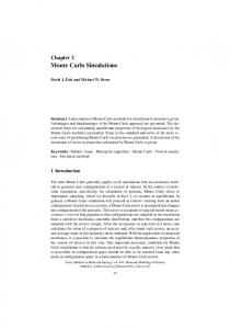
1 FIG. 1. 共Color online兲 Self-consistent ICRF heating simulation package using the 5D Monte Carlo finite-orbit code ORBIT-RF coupled with the 2D full-wave code AORSA.
found for the NSTX experiment. The discrepancy is likely due to the fact that the CQL3D computes fast-ion distribution with zero-orbit width approximation. It has been known that finite orbit motion of fast-ion may significantly modify ICRF wave propagation and absorption in the plasma.11 Therefore, this work is aimed at resolving this previous discrepancy by including finite drift orbit width effect in computing fast-ion distribution. For this, substantial computational work has been done through collaborations with the RF SciDAC community.12 As a result, the five-dimensional 共5D兲 Monte Carlo code ORBIT-RF 共Ref. 13兲 is successfully coupled with the twodimensional 共2D兲 global-wave field code all-orders spectral algorithm 共AORSA兲.14 Figure 1 explains how two codes are combined in a self-consistent way. ORBIT-RF computes a particle distribution function of an ensemble of fast-ion species in velocity and spatial space by solving a set of Hamiltonian guiding center drift orbit equations under Coulomb collisions and quasilinear 共QL兲 diffusive wave heating. Detailed description for ORBIT-RF is given in Sec. III. AORSA computes ICRF wave fields by solving Maxwell’s equations with oscillating current related to wave fields by a constitutive relation 共conductivity tensor兲. The particle distribution computed from ORBIT-RF is noisy due to Monte Carlo technique. Therefore, a new code P2F 共Ref. 15兲 was developed to reconstruct a smoothed distribution function from the noisy particle distribution to compute a dielectric tensor used in AORSA. Wave field amplitude and its spatial pattern computed from AORSA are passed to ORBIT-RF to evolve fast-ion distribution. Evolved fast-ion distribution is then fed back to AORSA to update the dielectric tensor and ICRF wave fields. In principle, iterations may be done until results converge. As similar self-consistent simulation packages, there are SELFO 共Ref. 16兲 and TASK/WM/GNET.17 However, these packages have some limitations when applied to high harmonic ICRF heating experiments in shaped plasmas, since TASK/WM is currently valid up to second harmonic, and FIDO is developed for a circular shaped plasma. Therefore, the success of this iteration between ORBIT-RF and AORSA motivates simulations of high harmonic ICRF heating experiments to understand the effect of nonzero orbit width on fast-ions in DIII-D and NSTX experiments.
0 3
(c)
Neutrons (x1014 s-1)
2 1 0
Neutrons without FW acceleration 1
2
Time (s)
3
4
FIG. 2. 共Color online兲 Time traces of experimental data from the DIII-D discharge 122993 for fifth harmonic central damping of 60 MHz ICRF wave on injected beam ions 共a兲 beam power 共dash兲 and ICRF wave power 共solid兲, 共b兲 central electron density 共dash兲 and central electron temperature 共solid兲, and 共c兲 measured neutron rate during ICRF heating 共solid兲 and computed rate from TRANSP without ICRF 共dash兲.
This paper is organized as follows. In Sec. II, the DIII-D and NSTX high harmonic ICRF heating experimental results are described. To model fast-ion resonant interaction with the ICRF wave in these experiments, Hamiltonian guiding center equations following fast-ion trajectory with finite drift orbit width are solved with Monte Carlo collision and QL heating operators. Details on numerical modeling work are given in Sec. III. In Sec. IV, latest simulation results from ORBIT-RF coupled with AORSA on DIII-D and NSTX heating experiments are presented and compared to the measurements from FIDA and neutron detector, and also with previous CQL3D/ GENRAY simulations. Lastly, a summary is given in Sec. V.
II. HIGH HARMONIC ICRF HEATING EXPERIMENTS IN DIII-D AND NSTX A. DIII-D
Figure 2 shows time traces of experimental data from the discharge 122993 in which fifth harmonic 60 MHz ICRF waves were damped near the plasma center on injected deuterium 共D兲 beam ions.4 Major radius at magnetic axis is R0 = 1.75 m, the minor radius a = 0.6 m, and the toroidal magnetic field B0 = 1.54 T. Neutral beams inject 1.2 MW of 75–81 keV D ions in the plasma in the direction of plasma current Ip ⬃ 1.0 MA. Tangency radius is 1.15 m 共the left
Downloaded 14 Jan 2011 to 198.35.3.144. Redistribution subject to AIP license or copyright; see http://pop.aip.org/about/rights_and_permissions
056102-3
2.5 NB Power (MW) 2.0 1.5 1.0 0.5 0.0 4 128742 w/o RF 3 2 1 0 4 3 2
Phys. Plasmas 17, 056102 共2010兲
Iterated finite-orbit Monte Carlo simulations…
128739 w/ RF 128740 w/ RF 128741 w/ RF
B. NSTX
(a) HHFW Power (MW)
(b)
Density (x10 19 m-3)
Te (keV) 128742 w/o RF 128739 w/ RF 128740 w/ RF 128741 w/ RF
(c)
Neutrons (x10 13 s-1)
1 0 0.10
0.15
0.20
0.25 0.30 Time (s)
0.35
0.40
FIG. 3. 共Color online兲 Time traces of experimental data from NSTX ICRF heating discharges 共128739–128741兲 and no ICRF discharge 共128742兲 for eighth harmonic central damping of 30 MHz ICRF wave on injected beam ions 共a兲 beam injection power 共dash兲 and ICRF wave power 共solid兲, 共b兲 central electron density 共ICRF shots for solid with symbol 夝, no ICRF shot for dash with symbol 夝兲 and central electron temperature 共ICRF shots for solid with symbol +, no ICRF shot for dash with symbol +兲, and 共c兲 measured neutron rates from three identical ICRF shots 共solid兲 and one no ICRF shot 共dash兲.
Time traces of NSTX experimental data6,7 are shown in Fig. 3. The three shots, 128739, 128740, and 128741, are nominally identical ICRF heating discharges, whereas the discharge 128742 is a reference discharge with the same neutral beam 共NB兲 timing and power but no ICRF heating. R0 = 104 cm, a = 67 cm, and B0 = 0.55 T. In all discharges, 1.0 MW beam injects 65 keV D beam ions in the direction of plasma current Ip ⬃ 0.8 MA from 150 to 400 ms. Tangency radius is 0.59 m. 1.1 MW ICRF power with 30 MHz frequency is coupled to the plasma from 210 to 370 ms for three ICRF heating discharges 关Fig. 3共a兲兴. 12-strap antenna is used to launch 30 MHz ICRF power with k储 = 7 m−1. At B0 = 0.55 T, the 30 MHz ICRF wave interacts with the D ions at several cyclotron resonance layers 共third–11th兲 along the major radius. The eighth harmonic layer is located near the magnetic axis at R = 104 cm. Figure 3共b兲 shows that larger increase in ne共0兲 is measured during ICRF heating, compared with the no-ICRF heating discharge, whereas the change of Te共0兲 due to ICRF heating is small. When the ICRF heating turns off, ne共0兲 = 3.0⫻ 1013 cm−3, Te共0兲 = 1.0 keV, and Ti共0兲 = 1.0 keV. Measured neutron emission increases about a factor of 3 during ICRF heating 关Fig. 3共c兲兴.
III. MODELING OF FAST-ION RESONANT INTERACTION WITH ICRF WAVE A. Fast-ion guiding-center drift motion
Equations 共1兲–共4兲 are Hamiltonian guiding-center drift equations18 implemented in ORBIT-RF to solve fast-ion motion including nonzero drift orbit width in the plasma source兲. After neutral beam preheats the plasma, 1.0 MW ICRF power is coupled to the plasma for a 1.5 s pulse 关Fig. 2共a兲兴. Four-element phased array is used to launch 60 MHz ICRF power into the plasma in countercurrent drive phasing with a peak in the vacuum spectrum at k储 = 5 m−1. At B0 = 1.54 T, the 60 MHz ICRF wave interacts with the D beam ions at three cyclotron resonance layers along the major radius, the fourth harmonic at R = 136 cm, the fifth at R = 174 cm near plasma center, and the sixth at R = 206 cm. Resonant interaction occurs mostly at fifth harmonic. Figure 2共b兲 indicates that the central electron temperature, Te共0兲, increases slightly during ICRF heating. During the discharge, typically, ne共0兲 = 3.0⫻ 1013 cm−3, Te共0兲 = 2.0 keV, central plasma ion temperature Ti共0兲 = 3.0 keV, and the effective charge Zeff ⬇ 2.0. As shown in Fig. 2共c兲, measured D-D 共mostly from beam-plasma reactions兲 neutron emission increases about a factor of 2 during ICRF heating. This demonstrates fast beam-ions are accelerated by the ICRF heating. Neutron rate becomes stationary approximately after 200 ms. Spectroscopic measurement of cold H-alpha and D-alpha lines indicates that the hydrogen concentration is usually below 1% during this discharge.5 Therefore, the resonant interaction between the ICRF wave and minority hydrogen is ignored in this work.
再
冎
B I B g ˙ p = − 共 + 2储 B兲 + 共 + 2储 B兲 , D D
再 冎
储B2 q B , 共1 − 兵储g其兲 + 共 + 2储 B兲 ˙ = D D p ˙ 储 = −
共1兲
共2兲
共1 − 兵储g其兲共 + 2储 B兲 B 共q + 兵储I其兲共 + 2储 B兲 B − , D D 共3兲
再 冎
储B2 I B 共q + 兵储I其兲 − 共 + 储 B兲 ˙ = . D D p
共4兲
Magnetic field perturbations and radial electric fields are ignored. Here, D = gq + I + 储关gI − Ig兴, p is the poloidal flux coordinate, is the poloidal angle, 储 is the normalized parallel gyroradius, is the angular coordinate, and is the magnetic moment. The Jacobian of these flux coordinates is given by J−1 = ⵜp ⫻ ⵜ • ⵜ. The function g共p兲 is the poloidal current, I共p兲 is the toroidal current, and q共p兲 is the safety factor. Equilibrium data for g共p兲, I共p兲, q共p兲, and B共p , 兲 are read from EFIT.19
Downloaded 14 Jan 2011 to 198.35.3.144. Redistribution subject to AIP license or copyright; see http://pop.aip.org/about/rights_and_permissions
056102-4
Phys. Plasmas 17, 056102 共2010兲
Choi et al.
8 G-C equations without drift Fast Ion Density (au)
Z/a
1.0
E ~ 61 keV Pitch ~ 0.05
0.0
6
4
2 Orbit-RF 0.0
–1.0 –1.0
0.0 x/a
1.0
FIG. 4. 共Color online兲 Single fast-ion trajectory solved from Hamiltonian guiding center equation with drift terms 共circle兲 and without drift terms 共diamond兲. Simulations are done for a few bounce times with fast ion energy 60 keV and pitch 0.04. Dashed line is assumed harmonic resonance layer.
The change in parallel velocity of fast-ion due to Coulomb collision with background plasma is calculated using slowing-down frequency between ion-ion and ion-electron,20 given by ⌬v储 = − v储⌬t,
共5兲
−3/2 储 = 1.6 ⫻ 10−9A−1 ne共兲Zf2⌳f共兲 f T e共 兲
⫻关1 + 共Ec/Ef兲3/2兴共1/s兲.
共6兲
The change in pitch angle 共p兲 induced by scattering between fast-ion and plasma ion is modeled by20 ⌬p = − p⬜⌬t + Rs冑共1 − p2兲⬜⌬t,
共7兲
⬜ = 1.8 ⫻ 10−7Af−1/2Ef−3/2ni共兲Z2i ⌳f共兲共1/s兲.
共8兲
In Eqs. 共5兲–共8兲, Ec = 14.8⫻ Af / A2/3 i Te共兲 is the critical energy, Af is the atomic mass number of fast-ion, ⌳f is the Coulomb logarithm, Ef is fast-ion energy, ni is the plasma ion density, ne is the plasma electron density, and the subscripts f and i denote fast-ion and background thermal-ion, and Rs is a random number. We assume that the density and temperature of background plasma ions and electrons, obtained from experimental data, are fixed during simulations. The change in due to the ICRF heating is computed using stochastic QL diffusive wave heating operator, which is described in Sec. III B. Quantities inside 兵 其 in Eqs. 共1兲–共4兲 describe drift orbit width terms. To understand effect of drift orbit terms on a
0.2
0.4
0.6
0.8
1.0
FIG. 5. 共Color online兲 Fast-ion density profile solved from Hamiltonian guiding center equation with drift terms 共solid兲 and without drift terms 共dot兲 during ICRF wave heating, indicating radial diffusion of ICRF heated fastions. Simulations are done for initial 20 toroidal turns with 80 keV deuterium fast-ions.
trajectory of fast-ion along magnetic flux surface, Eqs. 共1兲–共4兲 are solved for a single fast-ion with energy of 60 keV and pitch of 0.04 with and without drift terms. Simulations are done for a few bounce times. As shown in Fig. 4, when drift terms are included, fast-ion moves across flux surfaces and makes banana orbit trajectory, whereas fast-ion stays at the same flux surface when ignored. In case a resonance layer is located close to magnetic axis, the zero orbit fast-ion trajectory intersects always two resonance points, whereas banana orbit characteristic fast-ion passes through four resonant points, which may produce much broader local wave absorption profile.11 In addition, fast-ion drift motion across flux surface may induce radial diffusion of fast-ion when fast-ion is heated by the ICRF wave in the presence of collisions. To understand this, simple simulations are performed using an ensemble of 80 keV D ions for 20 toroidal transit times. As shown in Fig. 5, results demonstrate ICRF heated fast-ions near magnetic axis move outward in radial direction when drift terms are included. However, when ignored, heated fast-ions do not move radially since they are forced to stay at the same flux surface and thus spatial diffusion is not produced. Therefore, allowing of fast-ion motion with finite orbit drift terms is important for more accurate modeling. B. Stochastic quasilinear diffusive wave heating
In this work, the QL theory21 is used to model resonant interaction of fast-ion with the ICRF wave. It is based on stochastic diffusion of fast-ion in velocity space. When ions pass through ion cyclotron resonance layers, they may either absorb energy from or lose energy to the wave, depending on their phase difference with respect to the wave polarization.
Downloaded 14 Jan 2011 to 198.35.3.144. Redistribution subject to AIP license or copyright; see http://pop.aip.org/about/rights_and_permissions
056102-5
NB Only
(a)
0
0
NUBEAM PNB = 1.2 MW Ep = 80, 40, 25 keV
ORBIT-RF PNB = 0.9 MW Ep = 80 keV 40 Beam Energy (keV)
–1 0
80
(b)
NB Only
1
Pitch
Pitch
1
–1 0
Phys. Plasmas 17, 056102 共2010兲
Iterated finite-orbit Monte Carlo simulations…
40 Beam Energy (keV)
80
FIG. 6. 共Color online兲 Contour plots of fast beam-ion distributions computed from 共a兲 ORBIT-RF and 共b兲 NUBEAM for DIII-D 122993 before ICRF heating turns on.
Assuming that resonant ions lose their phase information with ICRF wave through successive collisions and wave stochasticity before they reenter the resonance region, a random walk model is appropriate, as shown in Eq. 共9兲, to reproduce stochastic nature in space ⌬ =
兺
关具⌬典 + Rs冑具⌬2典兴.
共9兲
particles
A time independent mean change 共具⌬典兲, representing drag, and rapidly fluctuating part 共冑具⌬2典兲, representing dispersion, are derived by connecting Brownian motion theory of individual particle to FP equation by Chandrasekhar.22 As a result, 具⌬典 is formulated as,23 具⌬典 =
q 2l 2⍀ 2 K兩E+兩2 ⫻ m 2B
冋冏
+ 2 Jl−1 + e2ik
E− Jl+1 E+
⫻
冉
再冉
Jl−1 + e2ik
Jl−1 E− Jl+1 + e2ik E+
冊 冊冎册
E− Jl+1 E+
␦共wl兲,
冏
2
共10兲
where Jl⫿1 is the 共l ⫿ 1兲th order Bessel function of the first kind, l is the ion cyclotron harmonic number wl = − l⍀ − k储v储 determining the resonance condition, is the wave frequency, ⍀ is the ion cyclotron frequency, k储 is the parallel wave number, v储 is the parallel velocity, = v⬜ / ⍀ = 冑2B / ⍀, B is the magnetic field, v⬜ is the perpendicular velocity, k⬜ is the perpendicular wave number, m is fast-ion mass, k defined as the direction of wave in x-y plane, cos k共x , y兲 = kx / k⬜, and sin k共X , Z兲 = ky / k⬜. Energetic ions absorb power at high harmonics of the ion cyclotron frequency, where Finite Larmor Radius 共FLR兲 effects are important. The argument of Bessel function, k⬜ ⫻ i takes into account this FLR effect. A factor K, associated with the integral over 储, physically related to a resonant interaction time, is present to account for correlation effect when energetic particle orbit intersects two resonances close to each ˙ = 0. other or resonance is located at turning point where ⍀ The expression for 具⌬2典 is similarly formulated.23 E+ and E−, defined as E⫾ = 共Ex ⫾ iEy兲, are the left-hand and right-hand polarized components of ICRF wave electric field. In fundamental or low harmonic heating experiments
such as in the Alcartor C-Mod tokamak, E− component does not play a significant role in ⌬ due to k⬜ Ⰶ 1. However, in high harmonic ICRF heating regimes that we simulate in this work, the contribution of E− component in ⌬ is not negligible due to large k⬜. For example, in DIII-D heating experiments, typically ⬇ 3 cm, while in NSTX it can be up to ⬇ 20 cm depending on fast-ion energy and magnetic field.10 Magnitude and structure of E+ and E− are computed from AORSA, which is described in Sec. III D.
C. Beam fast-ion slowing down distribution
As shown in Fig. 2共a兲, 1.2 MW beam injection preheats the plasma before the ICRF waves are coupled to the plasma. Therefore, the beam preheated plasma is first simulated to reproduce the experimental conditions before the ICRF heating. Figure 6 shows the Monte Carlo beam fast-ion distribution function in phase space computed from ORBIT-RF 关Fig. 6共a兲兴 and NUBEAM 共Ref. 24兲 关Fig. 6共b兲兴 before the ICRF turns on. The experimental data for the DIII-D discharge 122993, as shown in Fig. 2, is used. In the experiment, the beam has three energy components 共full: half: one-third兲. In usual DIII-D discharges, their fractions are 75%:15%:10%, respectively. In ORBIT-RF, only the full energy component is simulated. Therefore the beam injection power is adjusted to 0.9 MW 共75% of averaged experimental beam power 1.2 MW兲. Beam fast-ion slowing down distribution computed from ORBIT-RF is in reasonable agreement with NUBEAM computed distribution with three beam energy components at 1.2 MW beam power. Since fast-ion contributions from half and one-third energy components to FIDA measurement are ignorable due to very little acceleration of these low energy ions, modeling of injected beam fast-ion with a single full energy component with adjusted beam power would not affect significantly our comparison results between ORBIT-RF/AORSA and FIDA. The presence of MHD, possibly leading to nonclassical fast ion redistribution, may lead to inaccurate modeling of the distribution from simulation codes. The discharges have sawteeth but other MHD is negligible; the effect of the sawteeth on fast-ion redistribution is ignored in our simulations.
D. The ICRF wave fields
The ICRF wave field magnitude and spatial pattern in the plasma, used to compute “kicks” in the magnetic moment in expressions 共9兲 and 共10兲, are computed from AORSA, as described in Sec. I. Figure 7 shows E+ and E− components of the ICRF wave fields in 共R , Z兲 space for the DIII-D discharge 122993 ICRF heating parameters. Beam fast-ion distribution shown in Fig. 5 is used as initial beam ion condition. The phase difference between E+ and E−, which is not computed by AORSA, is assumed to be zero. Toroidal mode number N = 13 is set, which corresponds to a peak k储 in the antenna spectrum. Wave amplitudes are normalized with launched ICRF power 1.0 MW, assuming launched power is 100% absorbed by the plasma.
Downloaded 14 Jan 2011 to 198.35.3.144. Redistribution subject to AIP license or copyright; see http://pop.aip.org/about/rights_and_permissions
Phys. Plasmas 17, 056102 共2010兲
Choi et al.
(a) 4th
(b) 4th
5th 6th
1.0
100
5th 6th
4
(a)
Energy (keV)
60 40
Z (m)
20
Z (m)
0th iteration 1st iteration 2nd iteration
2
1.0
0.0
x10 4 (c)
80
E+ (V/m)
056102-6
–2
160
0.0
0
170
180
200
190
160
R (cm) 100
170
180
190
200
R (cm)
(b)
80
–1.0 1.2
1.6 2.0 R (m)
1.2
1.6 2.0 R (m)
60
Energy (keV)
–1.0
40 20
FIG. 7. 共Color online兲 Contour plots of ICRF wave electric fields computed from AORSA for 共a兲 E+ and 共b兲 E− using N = 13 and PRF = 1.0 MW for DIII-D 122993 ICRF heating parameters.
IV. RESULTS
160
170
180
200
190
R (cm)
FIG. 8. 共Color online兲 Contour plots of fast beam-ion distribution computed from ORBIT-RF 共a兲 before ICRF wave turns on, 共b兲 after ICRF wave turns on, and 共c兲 E+ component of ICRF wave electric field computed from AORSA at zeroth iteration 共dot兲, first iteration 共dash兲, and second iteration 共solid兲, for DIII-D 122993 heating parameters.
A. DIII-D discharge 122993
fast ion tails are continuously being accelerated above beam injection energy 共80 keV兲 due to the ICRF heating. In Figs. 10 and 11, fast-ion tail spectra and spatial profile computed from ORBIT-RF/AORSA are compared to those measured from FIDA and computed from CQL3D/GENRAY. The FIDA signal is integrated over particular wavelengths that are related to fast-ion energies with a response function to take into account an effective averaging over phase-space, specific viewing and beam geometry and recombination rate of fast ions.4 Fast ion distribution functions simulated from Beam Injection Energy (a)
0
Beam Injection Energy 1
Pitch
Pitch
1
-1 0
100 200 Beam Energy (keV)
300
(b)
0
-1 0
Beam Injection Energy 1
0
-1
100 200 300 Beam Energy (keV) Beam Injection Energy
1
(c)
Pitch
Pitch
ORBIT-RF is iterated twice with AORSA including QL and collisional orbit diffusion for 160 ms 共approximately one slowing down time兲. First iteration between fast ion distribution and ICRF wave field is done at 80 ms. Figure 8共a兲 shows beam fast-ion distribution, f共E , R兲, where E is the beam-ion energy and R is the major radius, calculated by ORBIT-RF before the ICRF turns on. Beam injection energy and tangency radius are 80 keV and 115 cm, respectively. In Fig. 8共b兲, structure and magnitude of E+ component of ICRF wave field computed from AORSA using the particle distribution function as given in Fig. 8共a兲 are shown as a dotted curve. ORBIT-RF evolves fast-ion distribution 关Fig. 8共a兲兴 with ICRF wave fields 关Fig. 8共b兲兴 during the first 80 ms. As a result, fast-ion distribution is modified due to ICRF induced kicks, as shown in Fig. 8共c兲, and beam tails are built-up above the beam injection energy. This modified distribution is passed on to AORSA to update the dielectric tensor and recompute ICRF wave fields. Dash-dotted curve in Fig. 8共a兲 shows the modified ICRF wave field structure and magnitude, indicating that the amplitude of ICRF wave field is reduced at the resonant layer 共marked with bar兲 since the ICRF wave is damped strongly on fast ion tail. Solid curve in Fig. 8共a兲 shows the modified wave field after a second iteration between fast-ion distribution and ICRF wave field. For this case, wave fields appear to rapidly converge after two iterations. This supports the validity of the proposed iteration scheme. In Fig. 9, the evolution of fast-ion distribution, f共E , p兲 where p is the particle pitch, is plotted at three consecutive time slices during the 160 ms computation time interval after the ICRF wave turns on at t = 20 ms 关Fig. 9共b兲兴, t = 70 ms 关Fig. 9共c兲兴, and t = 160 ms 关Fig. 9共d兲兴. Figure 9共a兲 is the initial beam distribution before ICRF turns on. It shows that
(d)
0
-1 0
200 100 Beam Energy (keV)
300
0
200 100 Beam Energy (keV)
300
FIG. 9. 共Color online兲 Contour plots of fast-ion distribution computed from ORBIT-RF coupled with AORSA 共a兲 before ICRF wave turns on, 共b兲 at 20 ms after ICRF turns on, 共c兲 at 70 ms after ICRF turns on, and 共d兲 at 160 ms after ICRF turns on, for DIII-D 122993, indicating that beam tails are being created above the beam injection energy 80 keV during ICRF heating.
Downloaded 14 Jan 2011 to 198.35.3.144. Redistribution subject to AIP license or copyright; see http://pop.aip.org/about/rights_and_permissions
056102-7
Phys. Plasmas 17, 056102 共2010兲
Iterated finite-orbit Monte Carlo simulations…
4 D
Fast ions (au)
Fast Ions (au)
Orbit-RF/AORSA
CQL3D/Genray
D
Measurement
3
Orbit-RF/AORSA (160 ms) (80 ms)
2 1
10
CQL3D/Genray
Measurement
170
30
40
50 Eλ (keV)
60
70
FIG. 10. 共Color online兲 Fast-ion spectra from FIDA 共signal ⫻ with error bar兲, CQL3D/GENRAY 共dashed line兲 and ORBIT-RF/AORSA 共solid line兲 for DIII-D 122993 fifth harmonic ICRF heating discharge. Here, E is the component of fast-ion velocity along vertical collection lens.
190 R (cm)
180
200
210
FIG. 11. 共Color online兲 Fast-ion spatial profiles from FIDA 共signal ⫻ with error bar兲, CQL3D/GENRAY 共solid with 䉱兲, ORBIT-RF/AORSA 共dashed line with 쎲 for 80 ms simulation and solid line with 쎲 for 160 ms simulation兲 for DIII-D 5th harmonic ICRF heating discharge 122793. Here, vertical dotted lines are fifth and sixth harmonic resonance layers of injected deuterium beam ions.
tively consistent with FIDA measurement, whereas CQL3D/ predicts more peaked radial profile near magnetic axis near primary fifth harmonic resonance layer. A noted discrepancy is that fast ions computed from ORBIT-RF/ AORSA indicate more outward radial shift than the peak observed from FIDA. GENRAY
ORBIT-RF/AORSA and CQL3D/GENRAY are used as inputs to the FIDA simulation code4 to include a response function in simulations for more quantitative comparison. Three curves for fast-ion spectra in Fig. 10 are obtained at major radii that indicate peaks of fast-ion density in each case. Both ORBIT-RF/AORSA and CQL3D/GENRAY predict fast-ion tail spectra qualitatively consistent with FIDA. As a quantitative measure of fast-ion acceleration due to the ICRF heating, the neutron enhancement factor Sn is calculated using the ratio of neutron reaction rates between NB only 共no ICRF兲 and NB coupled with the ICRF wave, given by
冉兺 冊 冒 冉兺 冊
Sn =
nc
具 v 典 iw i
i=1
具 v 典 iw i
NBonly
,
共11兲
Among the three identical ICRF shots shown in Fig. 3, the discharge 128739 is simulated in this work. ORBIT-RF is run for about 50 ms with the ICRF wave fields computed from AORSA. No iteration is done on this preliminary work. ICRF heated fast-ion tail spectra and spatial profile computed from ORBIT-RF/AORSA are compared to those measured from FIDA and computed from CQL3D/GENRAY in Figs. 12 and 13. Similarly, three curves for fast-ion spectra in
i=1
where nc is the number of Monte Carlo test ions, 具v典 is the reaction rate for beam-plasma, and wj is the weighting of each fast-ion. Sn is computed as ⬃2.1 from ORBIT-RF/ AORSA, which is slightly smaller than experimental number measured from the neutron detector, 2.4. This is likely due to that the neutron rate keeps increasing in experiment 关Fig. 2共c兲兴 until 200 ms, whereas the simulation is done for 160 ms. Therefore, for a more quantitative comparison to the measured data from stationary state, simulation should be extended to a longer time scale. Figure 11 compares fast-ion spatial profiles from the theory and the experiment. As discussed earlier, the ICRF wave field is updated after fast-ion is evolved for 80 ms. Two ORBIT-RF/AORSA results are shown at 80 and 160 ms evolution. As shown in Fig. 9, fast-ion distribution is continuously evolving during 160 ms, which is expected from increasing neutron rates from experiment until 200 ms 关Fig. 2共c兲兴. The fast-ion distribution computed for 160 ms reproduces outward spatial shift of ICRF heated fast-ion qualita-
Fast Ions (au)
NB+RF
nc
B. NSTX discharge 128739
Measurement 100
CQL3D/Genray
Orbit RF/AORSA 20
30
40 E (keV)
50
60
FIG. 12. 共Color online兲 Fast-ion spectra from FIDA 共signal ⫻ with error bar兲, CQL3D/GENRAY 共dashed line兲 and ORBIT-RF/AORSA 共solid line兲 for NSTX 128739 high harmonic ICRF heating discharge. Here, E is the component of fast-ion velocity along vertical collection lens.
Downloaded 14 Jan 2011 to 198.35.3.144. Redistribution subject to AIP license or copyright; see http://pop.aip.org/about/rights_and_permissions
056102-8
Phys. Plasmas 17, 056102 共2010兲
Choi et al.
3
Fast Ions (au)
CQL3D/Ray-tracing 2 8Ω D
9ΩD
Measurement 10ΩD Orbit-RF/AORSA
1
100
120
140
160
R (cm) FIG. 13. 共Color online兲 Fast-ion spatial profiles from FIDA 共dashed line is the averaged signal from three identical ICRF shots marked with ⴱ兲, CQL3D/GENRAY 共solid line with 䉱兲, ORBIT-RF/AORSA 共solid line with 쎲兲 for NSTX high harmonic ICRF heating discharge 128739. Here, vertical dashed lines indicate eighth–tenth harmonic resonance layers of injected deuterium beam ions.
Fig. 12 are obtained at major radii that indicate peaks of fast-ion density in each case. Both ORBIT-RF/AORSA and CQL3D/GENRAY predict fast-ion spectra qualitatively consistent with FIDA. Computed Sn from ORBIT-RF/AORSA is ⬃1.5, which is much smaller than experimental number, 2.5. Figure 13 shows that CQL3D/GENRAY computes a peak near magnetic axis, as expected, whereas ORBIT-RF/AORSA computes outward radial shift qualitatively consistent with FIDA. However, a similar discrepancy is found, showing more outward radial shift of fast ions than FIDA. V. SUMMARY AND DISCUSSION
Previous numerical study with zero-orbit approximation of fast-ion motion could not fully explain experimental observations in DIII-D and NSTX high harmonic ICRF heating experiments. In particular, a peak in radial fast-ion density profile measured from FIDA spectroscopy indicated outward radial shift from primary resonance layer near magnetic axis, whereas zero-orbit theory predicts a peak near magnetic axis. To assess finite drift orbit effect on this discrepancy, the 5D finite-orbit Monte Carlo code ORBIT-RF is coupled with the 2D full-wave code AORSA in a self-consistent way under the RF SciDAC project. Successful simulations of ORBIT-RF coupled by AORSA including QL and collisional orbit diffusion in both DIII-D and NSTX high harmonic ICRF heating experiments confirm that finite drift orbit effect on fast-ion motion and iterative simulation between fast-ion distribution and ICRF wave fields are important in modeling ICRF heating experiments. ORBIT-RF/AORSA simulations predict outward radial shift qualitatively consistent with FIDA in both DIII-D and NSTX, which cannot be reproduced by zero-orbit theory. This outward shift is due to radial diffusion of ICRF heated fast-ions across magnetic surfaces. As verified in Sec. II, finite drift orbit terms included in guiding center equations of fast-ion motion makes ICRF heated fast-ion move outward. As shown in Fig. 11, twice-iterated DIII-D simulation results
between fast-ion distribution and ICRF wave fields produce more consistent results with FIDA measurements than onceiterated result. Computed neutron rate is in reasonable agreement with measurement from neutron detector, though slightly smaller than measurement. A noted discrepancy is that ORBIT-RF/AORSA computes further outward shift from magnetic axis than FIDA. Data measured by FIDA data is averaged over a fairly long time window to get better statistics for the steady-state discharge, whereas simulations are done for 160 ms. This suggests simulations should be extended for more quantitative comparison to FIDA data from stationary phase. Further investigation such as statistics and convergence study is underway to improve the difference in peak of fast-ion density. Similar extensive study is also underway to resolve the discrepancy in NSTX result. ACKNOWLEDGMENTS
This work was supported in part by the U.S. Department of Energy under Contract Nos. DE-FG0395ER54309, DE-AC05-00OR22725, SC-G903402, and DEFG03-99ER54541. The authors would like to thank Professor M. Porkolab at MIT for his valuable discussions. 1
R. Aymar, V. A. Chuyanov, M. Huguet, Y. Shimomura, ITER Joint Central Team, and ITER Home Teams, Nucl. Fusion 41, 1301 共2001兲. 2 J. L. Luxon, Nucl. Fusion 42, 614 共2002兲. 3 M. Ono, M. G. Bell, R. E. Bell, T. Bigelow, M. Bitter, W. Blanchard, D. S. Darrow, E. D. Fredrickson, D. A. Gates, L. R. Grisham, J. C. Hosea, D. W. Johnson, R. Kaita, S. M. Kaye, S. Kubota, H. W. Kugel, B. P. LeBlanc, R. Maingi, R. Maqueda, E. Mazzucato, J. Menard, D. Mueller, B. A. Nelson, C. Neumeyer, F. Paoletti, S. F. Paul, Y.-K. M. Peng, S. Ramakrishnan, R. Raman, P. M. Ryan, S. A. Sabbagh, C. H. Skinner, T. Stevenson, D. Stutman, D. W. Swain, E. J. Synakowski, G. Taylor, A. Von Halle, J. Wilgen, M. Williams, J. R. Wilson, S. J. Zweben, R. Ackers, R. E. Barry, A. Bers, J. M. Bialek, P. T. Bonoli, M. D. Carter, J. Chrzanowski, W. Davis, E. J. Doyle, L. Dudek, P. C. Efthimion, R. Ellis, J. R. Ferron, M. Finkenthal, E. Fredd, T. Gibney, R. J. Goldston, R. E. Hatcher, R. J. Hawryluck, H. Hayashiya, K. W. Hill, T. R. Jarboe, S. C. Jardin, H. Ji, M. Kalish, P. LaMarche, L. L. Lao, K. C. Lee, F. M. Levinton, N. C. Luhmann, R. Majeski, J. Manickam, R. Marsala, T. K. Mau, B. McCormack, S. S. Medley, M. M. Menon, O. Mitarai, M. Nagata, N. Nishino, G. Oliaro, H. K. Park, R. Parsells, G. Pearson, T. Peebles, C. K. Phillips, R. Pinsker, G. D. Porter, A. K. Ram, J. Robinson, P. Roney, A. L. Roquemore, A. Rosenberg, M. Schaffer, S. Shiraiwa, P. Sichta, D. Stotler, B. C. Stratton, Y. Takase, W. R. Wampler, G. A. Wurden, X. Q. Xu, J. G. Yang, L. Zeng, and W. Zhu, Nucl. Fusion 41, 1435 共2001兲. 4 W. W. Heidbrink, Y. Luo, K. H. Burrell, R. W. Harvey, R. I. Pinsker, and E. Ruskov, Plasma Phys. Controlled Fusion 49, 1457 共2007兲. 5 R. I. Pinsker, M. Porkolab, W. W. Heidbrink, Y. Luo, C. C. Petty, R. Prater, M. Choi, D. A. Schaffner, F. W. Baity, E. Fredd, J. C. Hosea, R. W. Harvey, A. P. Smirnov, M. Murakami, and M. A. Van Zeeland, Nucl. Fusion 46, S416 共2006兲. 6 D. Liu, W. W. Heidbrink, M. Podestà, R. E. Bell, E. D. Fredrickson, S. S. Medley, R. W. Harvey, and E. Ruskov, Plasma Phys. Controlled Fusion 52, 025006 共2009兲. 7 M. Podesta, W. W. Heidbrink, R. E. Bell, and R. Feder, Rev. Sci. Instrum. 79 10E521 共2008兲. 8 W. W. Heidbrink, K. H. Burrell, Y. Luo, N. A. Pablant, and E. Ruskov, Plasma Phys. Controlled Fusion 46, 1855 共2004兲. 9 R. W. Harvey and M. G. McCoy, Proceedings of the IAEA TCM on Advances in Simulation and Modeling of Thermonuclear Plasmas, Montreal, Canada, 1992 共unpublished兲. 10 A. P. Smirnov and R. W. Harvey 共
[email protected]兲, Report CompX-2000–01, Ver. 2, http://www.compxco.com/genray.html. 11 M. Choi, V. S. Chan, L. A. Berry, E. F. Jaeger, D. L. Green, P. Bonoli, J. Wright, and RF-SciDAC Team, Phys. Plasmas 16, 052513 共2009兲.
Downloaded 14 Jan 2011 to 198.35.3.144. Redistribution subject to AIP license or copyright; see http://pop.aip.org/about/rights_and_permissions
056102-9 12
Phys. Plasmas 17, 056102 共2010兲
Iterated finite-orbit Monte Carlo simulations…
P. T. Bonoli, D. B. Batchelor, L. A. Berry, M. Choi, D. A. D’Ippolito, R. W. Harvey, E. F. Jaeger, J. R. Myra, C. K. Phillips, D. N. Smithe, V. Tang, E. Valeo, J. C. Wright, M. Brambilla, R. Bilato, V. Lancellotti, and R. Maggiora, J. Phys.: Conf. Ser. 78, 012006 共2007兲. 13 M. Choi, V. S. Chan, R. I. Pinsker, S. C. Chiu, and W. W. Heidbrink, Phys. Plasmas 12, 1 共2005兲. 14 E. F. Jaeger, L. A. Berry, E. D’Azevedo, D. B. Batchelor, M. D. Carter, K. F. White, and H. Weitzner, Phys. Plasmas 9, 1873 共2002兲. 15 D. L. Green, E. F. Jaeger, L. A. Berry, M. Choi, and RF-SciDAC Team, Proceedings of the 18th Topical Conference in Radio Frequency Power in Plasma 共Invited Paper兲, Ghent, Belgium, 2009 共unpublished兲. 16 J. Hedin, T. Hellsten, L.-G. Eriksson, and T. Johnson, Nucl. Fusion 42, 527 共2002兲.
17
A. Fukuyama, E. Yokota, and T. Akutsu, Proceedings of the 18th IAEA Conference on Fusion Energy, Sorrento, Italy, 2000 共unpublished兲. 18 R. B. White and M. S. Chance, Phys. Fluids 27, 2455 共1984兲. 19 L. L. Lao, H. E. St. John, Q. Peng, J. R. Ferron, E. J. Strait, T. S. Taylor, W. H. Meyer, C. Zhang, and K. I. You, Fusion Sci. Technol. 48, 968 共2005兲. 20 Physics Vade Mecum, edited by H. L. Anderson 共American Institute of Physics, New York, 1981兲, p. 63. 21 T. H. Stix, Nucl. Fusion 15, 737 共1975兲. 22 S. Chandrasekhar, Rev. Mod. Phys. 15, 1 共1943兲. 23 S. C. Chiu, V. S. Chan, Y. R. Lin-Liu, and Y. Omelchenko, Phys. Plasmas 7, 11 共2000兲. 24 R. V. Budny, Nucl. Fusion 34, 1247 共1994兲.
Downloaded 14 Jan 2011 to 198.35.3.144. Redistribution subject to AIP license or copyright; see http://pop.aip.org/about/rights_and_permissions