IEEE Computer Graphics and Applications
It's Really Not a Rendering Bug, You See…
September 1996
21
Andrew Woo and Andrew Pearce Alias-Wavefront Marc Ouellette University of Toronto
A
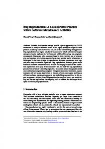
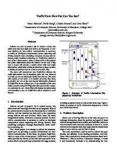
rtifacts of rendering, though often treated on a case-by-case basis, have not yet been treated as a class. We propose the non-exhaustive taxonomy shown in Table 1. Each category is treated at greater length in the following sections, and some workarounds are provided. Surface acne When ray tracing, you are intersecting rays with surfaces to determine visibility. The hit distance from the ray origin must be larger than some positive ε to qualify as a hit.1 Otherwise, floating-point precision problems can cause secondary rays (such as reflection, refraction, and shadow rays) to self-intersect incorrectly.2 For example, when this ε is not applied to shadow rays, incorrect selfshadowing causes small black dots (often referred to as surface acne) to appear on the surface. However, even using the ε check does not totally eliminate this problem. Black dots are still likely to occur when the shadow ray is very close to being perpendicular to the surface normal N. Then, as in Figure 1 (p. 22), no reasonable ε value can eliminate the incorrect self-shadowing if the intersection point with the viewing ray is off by just a little. Numerical inaccuracy of those Most rendering algorithms intersection points can result from single-precision deliberately employ floating-point math, or a faraway hit distance t. approximations and other
shortcuts for efficiency. These economies—not coding errors—produce characteristic image artifacts. This article classifies the best-known varieties.
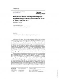
To elaborate on the cause of numerical instability in the latter case, let the intersection point be O + tD, where O is the ray origin and D is the ray direction. Then a large t value multiplied with D (normalized) can result in a numerically unstable answer. An effective workaround to this problem is available for planar polygons. You can adjust the intersection point for the viewing ray, x, to sit much closer to the visible polygon by shooting a ray in the reverse direction of the original ray, that is, x - t'D, and intersecting only against the plane on which the polygon resides. Thus the standard ray-plane intersection equations will serve: t' = (d - N • x)/(-N •D), where N • P = d defines the planar equation of the polygon. The better intersection point; x' = x - t'D, should be used as the start point to shoot second-generation rays. The point x' provides a numerically stable solution, since t' and D are very small, and a subtraction from x with a small number will be numerically stable as well. Figure 2 (p. 22) illustrates an example of surface acne, where the middle of the sphere contains black dots due to improper shadowing from a point light far to the right of the sphere. (For more images showing the surface acne artifacts, and more general proposals to alleviate this problem, refer to Amanatides and Mitchell.3) The ugly-looking black polygons will be explained next as part of the terminator problem.
Table 1. Taxonomy of rendering artifacts. Name Surface acne Terminator problem Phong vs. Phong Separation of diffuse and specular reflection Nature of mirror reflections
Symptoms Black dots Black Blotches Misshapen annulus
Visiblity inconsistency
Color confusion
Naïve texture interpolation
Warped textures
Misshapen annulus Misshapen annulus
Underlying Cause Grazing ray reintersection Improper self-shadowing Confusion in terminology Spatial misalignment of components Incorrect expectation of symmetry Mixed dominance of two surfaces Naïve linear interpolation
IEEE Computer Graphics and Applications
September 1996
22
In Figure 3, polygons A and B represent polygonal approximations to the smooth surface region. At point x on polygon A, the vertex-interpolated normal N' (instead of the planar normal N) is used to compute illumination. Since N' • L > 0, light contribution is present, and shadow occlusion must be computed to determine whether x is shadowed. The shadow ray for point x intersects polygon B and incorrectly concludes that x is in self-shadow. Use point x', which represents the correct intersection point on the actual surface, to avoid this problem (but x' is not easily computable).
1 Likelihood of surface acne artifacts.
The ugly black polygons around the shadow boundaries in Figure 2 are an example of terminator problem artifacts. Their most common formation is a stair-step pattern. Note that terminator problem artifacts occur in most shadow algorithms to varying degrees. You can reduce the size of the artifacts through finer tessellation of the surface (if the data is available).
2 Surface acne and terminator problem.
Snyder and Barr4 provided a workaround to compute x' that sometimes handles convex surfaces. The basic idea is to introduce a positive ε value along N that can allow the intersection point to escape the self-shadowing. The selection of ε, however, is user driven. If the value is too small, the problem persists; if the value is too large, then some regions can be incorrectly illuminated instead of shadowed. Phong versus Phong At least two very confusing issues exist for the models Phong proposed in his famous paper.6 First, two variations exist for what has often been called the Phong reflection model: one from the original paper by Phong and the other proposed by Blinn.7 The specular highlights from the two models can look very different. An approximation relating the two models can be derived,8 but even this approximation cannot possibly yield matching results in all situations.
3 Terminator problem.
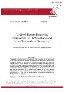
Also confusing, Phong actually proposed two ideas in the same paper. One is the above reflection model; the other is commonly known as Phong shading. Phong shading refers to the technique of vertex normal (linear) interpolation. The term "shading" is often carelessly employed in computer graphics to indicate (among other things) some sort of interpolation; for example, Gouraud shading means vertex color interpolation. It might be worthwhile to stop using the term "shading" as applied to Phong or Gouraud shading and use the term "interpolation" instead. 4 Unusual T-
The distinction between a reflection model and an interpolation model is very important. This distinction permits many combinations for surface rendering, such as using Gouraud interpolation with the Phong reflection model, Phong interpolation with the Phong reflection model, or Phong interpolation with Blinn's reflection models.7
shaped highlight pattern.
Terminator problem The terminator problem4 results from improper selfshadowing due to planar-polygon approximation of smooth surfaces. This problem extends to mirror reflection, refraction, and Gouraud shading,5 but we will discuss only the shadowing problem in any detail.
Separation of diffuse and specular reflection In Figure 4, the planar floor is illuminated by a single point light placed slightly above the floor. Based on expectations of the Phong reflection model,6 a rendering of this floor should
IEEE Computer Graphics and Applications
September 1996
23
contain a single circular highlight, not the T-shaped highlight seen in the figure. Figure 4 when rerendered produced Figure 5, a rendering with the specular component set to 0, and Figure 6, a rendering with the diffuse component set to 0. Clearly, the T-shaped highlight results from combining specular and diffuse highlights that happen to be located at different positions. The simple superposition of the disjoint specular and diffuse components results in the odd highlight shape. Summation of the different components is common in computer graphics, so it is surprising that this artifact is not better known. Another artifact results from segmenting the diffuse and specular components, as shown in Figure 7. Note that the highlight ends very abruptly, instead of smoothly dying off. This abrupt change and the (black) boundary occur because the diffuse evaluation indicates no light reaching it (that is, N • L < 0), but the specular evaluation still has some light contribution. Since N • L is the primary indicator of light reaching the point, the specular contribution is ignored in the illumination. Note that this artifact exists for most specular models, though Figure 7 is rendered using the Phong reflection model.6
5 Unusual highlight pattern with diffuse highlights only.
6 Unusual highlight pattern with specular highlights only.
Nature of mirror reflections Mirror reflections are a main benefit of ray tracing.1 With mirror reflections about planar surfaces you would expect symmetry, so Figure 8 might be puzzling. Note that the highlight shape, size, and location on the actual sphere are very different when mirrored in the two walls.
7 Highlight cutoff.
Reflective symmetry does not apply to specular highlights, since they are view dependent. In the case of reflection rays, mirrored specular highlights become reflection-ray dependent (that is, the reflection ray is the viewing ray in this case) according to Whitted's illumination model.1 Thus specular highlights are rarely symmetric when mirrored. In addition, the highlights reflected can depend on the polarization of light as well (see Wolf and Kurlander9). Visibility inconsistency In all approaches to determining visibility, the goal is to compute the closest visible surface. However, surfaces can be very close to each other in depth and still produce inconsistent visibility winners. Deciding on a consistent visibility winner can be tricky-so much so that most visibility implementations do not bother with the issue. One scenario in which the lack of a consistent visibility winner causes a big problem occurs when coincident surfaces have different colors assigned (see the sphere in Figure 9, p. 24). Without a strategy for determining a consistent visibility winner, such collisions arbitrarily choose the winner from pixel to pixel, which in most cases produces a mix of both objects' colors and a resulting color confusion.
8 Incorrect mirror reflection expectations.
IEEE Computer Graphics and Applications
September 1996
24
course, is to raise those surfaces marginally above the floor. Note that this visibility problem can also be caused by a more serious numerical problem instead of the exact depth issue. If the near clipping plane used in a non-ray-tracing environment is very small, the numerical precision for the surface depth in perspective space can be compromised easily. Then the perspective depth can result in incorrect visibility answers, which would also result in the artifacts already shown. Fortunately, most renderers permit user input into clipping plane values.
9 Incorrect visibility determination.
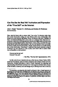
Naive texture interpolation Texture mapping adds interesting features to an otherwise matte surface. To texture-map polygons, common practice associates a (u, v) coordinate with each polygon vertex. This (u, v) is the index into the texture map. The (u, v) for any region inside the polygon is usually computed by linearly interpolating the vertices' (u, v) coordinates, a process easily done for a three-sided polygon (the triangle). Assuming interpolation in 3D space, linear interpolation of disproportionate triangle sizes can cause warping artifacts. (We are not talking about interpolation in the wrong space. Some papers10,11 have discussed interpolation in perspective space that can result in bad warping artifacts. This is actually a coding and logic error, and can be alleviated by employing hyperbolic interpolation11 or by interpolating in 3D space.)
10 Uneven quadrilateral.
For example, consider texture mapping a checkerboard onto a quadrilateral subdivided into two triangles, as illustrated in Figure 10. To map the texture onto the quadrilateral, it is natural to assign the four vertices of the triangle to the four corners of the texture. The texture is then linearly interpolated within each triangle. Another scenario where problems arise appears in Figure 9, where the partially transparent box and cylinder sit exactly on the floor. Thus the bottoms of those surfaces collide exactly with the floor, and weird artifacts occur when the scene is rendered. The easy way to resolve this, of
11 Poor texture interpolation.
As a result, exactly half the texture gets mapped to each triangle, as illustrated on the right-hand side of Figure 11. The texture is severely distorted because the two triangles differ so drastically in size and shape. The result is unexpected (intuitively and mathematically) for mapping the checkerboard across a quadrilateral. The result should look more like the left-hand side of Figure 11. One possible solution would be to apply nonlinear interpolation techniques, such as interpolation using C1 piecewise polynomial functions,12 but this can be computationally expensive. An alternative solution to this problem is to tessellate the quadrilateral more in both the u and v directions, assigning the correct vertex (u, v) so that the linear interpolation error within the smaller triangles is negligible (the left-hand quadrilateral in Figure 11 subdivided the object 15 times in u and v).
IEEE Computer Graphics and Applications
If you continue to use linear interpolation, its unfortunate limitations require an additional criterion for good polygon reduction and tessellation algorithms when texture mapping is involved. For tessellation algorithms, the poor texture interpolation problem is avoided by producing evenly sized polygons. For reduction or simplification algorithms, it is best to consider the linearity of the (u, v) coordinates before considering simplification of the region. Conclusions
We wrote this article in hopes of saving programmers a lot of time debugging something that is really not a bug, but instead a limitation of the algorithm. Our taxonomy is not exhaustive, but it does include many common rendering problems that we have encountered over the years. Most of these limitations can be circumvented with the proposed solutions. In reality, there are more workarounds than true solutions. This imbalance warrants more research into proper solutions to these and similar problems. Acknowledgments
Many thanks to Changyaw Wang, Eugene Fiume, Atjeng Gunawan, and Alan Paeth for proofreading this article and providing useful suggestions. Thanks also go to the reviewers for their useful comments. References 1. T. Whitted, "An Improved Illumination for Shaded Display," Comm. ACM, Vol. 23, No. 6, June 1980, pp. 343-349. 2. E. Haines, Essential Ray Tracing Algorithms, An Introduction to Ray Tracing, Academic Press, Cambridge, Mass., 1989, pp. 46-47. 3. J. Amanatides and D. Mitchell, "Some Regularization Problems in Ray Tracing," Graphics Interface, May 1990, pp. 221-228. 4. J. Snyder and A. Barr, "Ray Tracing Complex Models Containing Surface Tessellations," Computer Graphics, Vol. 21, No. 4, July 1987, pp. 119-128. 5. H. Gouraud, "Computer Display of Curved Surfaces," IEEE Trans. Computers, Vol. C-20, No. 6, June 1971, pp. 623-629. 6. B. Phong, "Illumination for Computer Generated Pictures," Comm. ACM, Vol. 18, No. 6, June 1975, pp. 311-317. 7. J. Blinn, "Models of Light Reflection for Computer Synthesized Pictures," Computer Graphics, Vol. 11, No. 2, July 1977, pp. 192-198. 8. F. Fisher and A. Woo, "R.E Versus N.H Specular Highlights," in Graphics Gems IV, P. Heckbert, ed., Academic Press, Cambridge, Mass., Aug. 1994, pp. 388-400. 9. L. Wolf and D. Kurlander, "Ray Tracing with Polarization Parameters," IEEE CG&A, Vol. 10, No. 6, Nov. 1990, pp. 44-55. 10. P. Heckbert, "Survey of Texture Mapping," IEEE CG&A, Vol. 11, No. 6, Nov. 1986, pp. 56-67. 11. J. Blinn, "Jim Blinn's Corner: Hyperbolic Interpolation," IEEE CG&A, Vol. 12, No. 4, July 1992, pp. 89-94. 12. N. Max, "Smooth Appearance for Polygonal Surfaces," Visual Computer, Vol. 4, 1989, pp. 160-173.
September 1996
25
Andrew Woo is senior R&D manager and has been at Alias Research (now Alias-Wavefront) for the last six years, having worked on Sketch! and Studio/PowerAnimator His interests lie in general rendering issues. Woo received a BS in 1987 for computer science and commerce, and an MS in 1989 for computer science, both at the University of Toronto. He is a member of IEEE, ACM, and CHCCS, and served as treasurer for the 'Toronto Local Siggraph group from 1989-1992.
Andrew Pearce is senior architect and has been involved in rendering at Alias-Wavefront for more than nine years, working on Studio/PowerAnimator He received a BS in 1984, and an MS in 1987, in computer science from the University of Calgary.
Marc Ouellette is a PhD candidate at the University of Toronto in the field of computer graphics, specializing in rendering. He has also been involved in rendering at Alias Research (now Alias-Wavefront) for the past two years. Ouellette received a Bmath in 1987 for pure mathematics and computer science from the University of Waterloo, and an MS for computer science in 1989 from the University of Toronto.
Readers can contact Woo and Pearce at Alias-Wavefront, 110 Richmond Street East, Toronto, Ontario, Canada, M5C 1P1; e-mail {awoo, pearce}@aw.sgi.com, and Ouellette at 10 King's College Road, Dept. of Computer Science, University of Toronto, Toronto, Ontario, Canada, M5S 3G4; e-mail
[email protected].