Copyright © 2012 Tech Science Press
MCB, vol.9, no.1, pp.77-93, 2012
IVUS-Based Computational Modeling and Planar Biaxial Artery Material Properties for Human Coronary Plaque Vulnerability Assessment Haofei Liu∗ , Mingchao Cai∗ , Chun Yang∗,† , Jie Zheng‡ , Richard Bach§ Mehmet H. Kural¶ , Kristen L. Billiar¶ , David Muccigrosso‡ Dongsi Luk , Dalin Tang∗,∗∗
Abstract: Image-based computational modeling has been introduced for vulnerable atherosclerotic plaques to identify critical mechanical conditions which may be used for better plaque assessment and rupture predictions. In vivo patientspecific coronary plaque models are lagging due to limitations on non-invasive image resolution, flow data, and vessel material properties. A framework is proposed to combine intravascular ultrasound (IVUS) imaging, biaxial mechanical testing and computational modeling with fluid-structure interactions and anisotropic material properties to acquire better and more complete plaque data and make more accurate plaque vulnerability assessment and predictions. Impact of pre-shrinkstretch process, vessel curvature and high blood pressure on stress, strain, flow velocity and flow maximum principal shear stress was investigated. Keywords: Coronary artery; cardiovascular; fluid-structure interaction; atherosclerotic plaque rupture, IVUS.
∗ Department
of Mathematical Sciences, Worcester Polytechnic Institute, Worcester, MA 01609
† School of Mathematical Sciences, Beijing Normal University, Key Laboratory of Mathematics and
Complex Systems, Ministry of Education, Beijing, 100875, China Institute of Radiology, Washington University School of Medicine, St. Louis, MO 63110 USA § Cardiovascular Division, Washington University School of Medicine, Saint Louis, MO 63110, USA ¶ Department of Biomedical Engineering, Worcester Polytechnic Institute, Worcester, MA 01609 k Department of Pathology & Immunology, Washington University School of Medicine, Saint Louis, MO 63110, USA ∗∗ Dalin Tang, Corresponding author, 508-845-1575,
[email protected] ‡ Mallinckrodt
78 1
Copyright © 2012 Tech Science Press
MCB, vol.9, no.1, pp.77-93, 2012
Introduction
Atherosclerotic plaques may rupture without warning and cause acute cardiovascular syndromes such as heart attack and stroke. It is commonly believed that plaque rupture may be linked to critical stress/strain conditions. Image-based computational models have been developed by several groups combining mechanical analysis with image technology aiming to identify critical flow and stress/strain conditions which may be related to possible plaque rupture [1-11]. Our previous publications provided in vivo evidence that that plaque rupture may be linked to critical stress/strain conditions [12-13]. However, existing in vivo 3D plaque models are mostly for carotid plaques based on magnetic resonance imaging (MRI) data. Similar models for coronary plaques based on in vivo image data are rare in the current literature [14-18] because clinical recognition of vulnerable coronary plaques has remained challenging and beyond the capability of non-invasive diagnostic imaging such as MRI and CT coronary angiography. Coronary imaging is more difficult because: a) coronary arteries move with the pumping heart constantly; b) coronary artery has smaller dimensions compared to carotid arteries; c) coronary arteries are not as accessible as carotid arteries; and d) plaque components are not reliably delineated as in carotid arteries. Traditional invasive x-ray angiography can delineate luminal stenosis, but not plaque components. Intravascular ultrasound (IVUS) imaging with tissue characterization represents the most promising and potentially clinically relevant technique for recognition of vulnerable plaques in vivo in patients [7].
A framework combining IVUS, mechanical testing and modeling is proposed in this paper to develop 3D in vivo IVUS-based models with fluid-structure interactions (FSI), cyclic bending and anisotropic properties to perform mechanical analysis for human coronary atherosclerotic plaques. The procedure includes a) IVUS acquisition of coronary plaque morphology and blood flow and pressure information; b) X-ray coronary angiography for coronary motion and curvature; c) biaxial mechanical testing of coronary plaque material properties; d) 3D computational modeling based on data acquired in a)-c). Cyclic bending represents the bending caused by cardiac motion and is included in the FSI model to evaluate its impact on stress conditions in coronary plaques. Anisotropic material models will be used for the vessel for more realistic modeling and more accurate computational flow and stress/strain predictions.
IVUS-Based Computational Modeling
2 2.1
79
Data acquisition, models and methods IVUS plaque image, flow velocity and pressure data acquisition, and x-ray angiography
One 3D IVUS data set was acquired during cardiac catheterization from a patient (male, age: 51) after voluntary informed consent. For IVUS image acquisition, a 20-MHz, 2.9F phased-array Eagle Eye Gold IVUS catheter (Volcano Corp., Rancho Cordova, CA) was positioned 2 cm beyond a stenosis in the mid segment of the right coronary artery. A pullback at 0.5mm/s was performed to 2 cm proximal to the lesion for recording digitized cross-sectional IVUS images. The catheter orientation was fixed at the proximal interface with the imaging console and the distal tip was constrained by the coronary guidewire that remained stationary in the monorail lumen. During the pullback, the IVUS images were recorded with electrocardiogram gating and then reconstructed from the RF data and plaque contour detection was performed using automated Virtual Histology (VH) software (ver 3.1) on a Volcano s5 Imaging System (Volcano Corp., Rancho Cordova, CA) to provide geometrical and compositional output. Four basic plaque tissue components were provided by VH images: (1) Fibrous tissue (dark green), (2) Fibro-fatty tissue (light green), (3) Necrotic core (red) and (4) dense calcium (white). Forty-five slices (selected from a 195-slice IVUS data set by picking one imaged during the diastole) covering the plaque region were used for model construction (Fig. 1). A two-step filtering-smoothing process was employed to convert the noisy IVUS-VH data to slices with smoothed plaque component contours for finite-element model construction: Step 1, an in-house software Atherosclerotic Plaque Imaging Analysis (APIA) written in Matlab was used to automatically generate contour plots of lumen, vessel out-boundary and plaque components with a smoothing filter to remove outliers with pixel size < 5 (IVUS system interpolated apparent pixel size was 20 µm). This filtering dimension (5 pixels = 0.1 mm) was empirically determined based on visual inspection of all VH images. Fibrous and fibro-fatty tissues were merged and treated as a uniform fibrous tissue; Step 2, the APIA-generated contour plots (Fig. 1(b)) were inspected slice by slice by the modeling group and further smoothing was applied to get slices ready for model construction. Isolated small components were removed. Components which are close to each other and with complex non-smooth contours were combined and outlined using cubic splines (Fig. 1(c)). Critical morphological features such as cap thickness were kept in the smoothing process. Figure 1 shows 22 IVUS-VH slices selected from the 45 slices used for the model, segmented contours by APIA, contours after smoothing, filtering and merging, and the 3D reconstructed geometry showing all 45 slices (Fig. 1 (g)). One sample slice with enlarged view was used to show the merging
80
Copyright © 2012 Tech Science Press
MCB, vol.9, no.1, pp.77-93, 2012
Figure 1. and smoothing details (Fig. 1 (d)-(f)). It should be noted that S44 is near the inlet
of the segment because IVUS recorded the slice numbers in a reversed way.
Figure 1: Selected IVUS slices from a 45-slice set, segmented contours by MPIA, contours after smoothing, filtering and merging, and 3D reconstructed geometry.
A Combo-Wire XT 9500 (Volcano Therapeutics, Inc.) 0.014-inch guide-wire with a Doppler flow velocity sensor at the tip was used (figure above) to acquire on-site blood pressure and flow velocity data. The pressure sensor was 15 mm offset from the flow sensor. The measurements were recorded digitally onto a ComboMap (Volcano Therapeutics, Inc.) console for offline analysis. Measurement of intracoronary flow velocity and blood pressure was acquired at baseline. An average of 5 beats was used to calculate average peak velocity (APV) at baseline. Blood pressure data was extracted from Pd, an 18 averaged pressure recorded on the pressure sensor. Although there is an offset between two sensors, the Pd should be very
IVUS-Based Computational Modeling
81
Figure 2: Screen shoot from an IVUS Combo-Wire for patient-specific on-site blood pressure acquisition and pressure conditions using in the models.
close to the pressure around the flow sensor. Figure 2 shows a snapshot of the ComboMap screen and the extracted inlet pressure profile. It should be noted that the outlet pressure profile is adjusted Outlet pressure was adjusted by trail-and-error to generate flow velocity matching the velocity measurement. The traditional x-ray angiogram (Allura Xper FD10 System, Philips, Bothel, WA) was obtained prior to the pullback of the IVUS catheter to determine the location of the coronary artery stenosis in patients (Fig. 3). Because this imaging modality can demonstrate the dynamic phasic changes of the coronary artery tree during the cardiac cycle with a high frame rate (30 frames / sec), we used x-ray angiographic data for the determination of the stenosis segment movement and curvature. Figure 3 gives one frame of x-ray angiographic image showing vessel curvature, the starting and ending locations of the segment we took for modeling, and the extracted curvature plot. 2.2
The 3D FSI model, boundary conditions, and the pre-shrink-stretch process
3D anisotropic and isotropic multi-component FSI models were constructed to calculate flow and stress/strain distributions using the plaque sample shown in Fig. 1. Blood flow was assumed to be laminar, Newtonian, and incompressible. The Navier-Stokes equations with arbitrary Lagrangian-Eulerian (ALE) formulation were used as the governing equations. On-site pressure conditions from IVUS measurements were prescribed at both inlet and outlet (see Fig. 2). No-slip conditions and natural traction equilibrium conditions are assumed at all interfaces. The vessel wall was assumed to be anisotropic whose constitutive equations and
82
Copyright © 2012 Tech Science Press
MCB, vol.9, no.1, pp.77-93, 2012
Figure 3: X-ray angiographic image used to determine the location of the myocardium and patient-specific curvature variations.
parameter values are given in next section. All other plaque components (lipid core for this sample) were assumed isotropic and parameters used in our previous publications were used in this paper [12]. Putting these together, we have: ρ(∂ u/∂t + ((u − ug ) · ∇)u) = −∇p + µ∇2 u,
(1)
∇ · u = 0,
(2)
u |Γ = ∂ x/∂t,
∂ u/∂ n|inlet,outlet = 0,
p|inlet = pin (t), ρvi,tt = σi j, j ,
p|outlet = pout (t), i, j = 1, 2, 3;
(4)
sum over j,
εi j = (vi, j + v j,i + vα,i vα, j )/2, i, j,
(3)
α = 1, 2, 3,
(5) (6)
σi j · n j |out_wall = 0,
(7)
σirj · n j |inter f ace
(8)
=
σisj · n j |inter f ace,
where u and p are fluid velocity and pressure, ug is the mesh velocity, µ is the dynamic viscosity, ρ is density, Γ stands for vessel inner boundary, f , j stands for derivative of the function f with respect to the jth variable, σ is stress tensor (superscripts ‘r’ and ‘s’ indicate different materials), ε is strain tensor, v is solid displacement vector. For simplicity, all material densities were set to 1 g·cm−3 in this paper.
IVUS-Based Computational Modeling
83
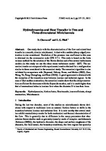
Figure 4: The biaxial testing apparatus and sample results showing 3D plots of measured stress-stretch data from a human carotid sample with fitting curves by the anisotropic Mooney-Rivlin model. Markers for protocols with 5 axial:circumferential stress ratios: ∗ : 1:1; X : 1:0.7; O: 1:0.5; +: 0.7:1; V:0.5:1.
Under the in vivo condition, the artery is axially stretched and pressurized. Therefore, we need to shrink the in vivo geometry both axially and circumferentially a priori to generate the start-shape for the computational simulation. With that, the vessel would be able to recover its in vivo geometry under pressure and with proper axial stretch. The circumferential shrinkage was determined to be 4% by trial-anderror for the vessel material used in this paper with axial shrinkage was set to 5%. It should be noted that circumferential shrinkage of the outer wall had to be different from the lumen shrinkage so that total mass (volume) of the vessel was conserved.
84 2.3
Copyright © 2012 Tech Science Press
MCB, vol.9, no.1, pp.77-93, 2012
Biaxial mechanical testing and anisotropic material models
A custom planar biaxial test device was used under stress control to obtain stress and strain measurements over a wide range of ratios of stress along the longitudinal and circumferential axes of arterial specimen splayed open to form square samples (see Fig. 4). The forces along the axes were measured via two torque transducers (effective resolution ∼0.02N) to determine the stress. Four graphite particles attached to the sample were tracked by a CCD camera to determine 2D strain (640 x 480 pixels; effective resolution ∼0.07% strain). The applied maximum longitudinal: circumferential stress ratios were 1:1, 0.7:1, 0.5:1, 1:0.7 and 1:0.5. Based on average stress in the vessel walls at systolic pressure, the maximum engineering stress applied was 250kPa. A modified Mooney-Rivlin (M-R) model was used to fit the biaxial data [12]: W = c1 (I1 − 3) + c2 (I2 − 3) + |D1 [exp(D2 (I1 − 3)) − 1] +
1 I1 = ∑ Cii , I2 = [I12 −Ci jCi j ], 2
K1 exp[K2 (I4 − 1)2 − 1], 2K2 (9) (10)
where I1 and I2 are the first and second invariants of right Cauchy-Green deformation tensor C defined as C =[Ci j ] = XT X, X=[Xi j ] = [∂ xi /∂ a j ], (xi ) is current position, (ai ) is original position, I 4 = Ci j (nc )i (nc ) j ,nc is the unit vector in the circumferential direction of the vessel, c1 ,D1 ,D2 , and K 1 and K 2 are material constants. A least-squares method was used to determine the parameter values in Eq. (1) to fit our experimental circumferential and axial stress-stretch data [12]. Five human coronary plaque samples were tested and the one with median stiffness was used in this paper. The parameter values are: c1 = -1312.9 kPa, c2 =114.7 kPa, D1=629.7 kPa, D2 =2.0, K1 =35.9 kPa, K2 =23.5. Figure 4 shows that our model with parameters selected with this procedure fits very well with the measured experimental data. Our measurements are also consistent with data available in the literature [19-20]. 2.4
3D re-construction of plaque geometry and component-fitting mesh generation method
All segmented 2D slices were assembled with the curvature given in Fig. 3 (b) and read into ADINA input file. 3D plaque geometry was re-constructed following the procedure described in Tang et al. [12]. Because plaques have complex irregular geometries with component inclusions which are challenging for mesh generation, a component-fitting mesh generation technique was developed to generate mesh for our models. Using this technique, each slice was first divided into
IVUS-Based Computational Modeling
85
component-fitting areas (called “surfaces” in ADINA). The neighboring slices were stacked to form volumes. Four types of volumes (hexahedron, prism, pyramid, and tetrahedron) were used to form regular (hexahedron) volumes and special volumes when the component changes drastically from one slice to the next slice. With this method, the 3D plaque domain was divided into hundreds of small “volumes” to curve-fit the irregular plaque geometry with plaque component inclusions. 3D surfaces, volumes and computational mesh were made under ADINA computing environment. Mesh analysis was performed by decreasing mesh size by 10% (in each dimension) until solution differences were less than 2%. The mesh was then chosen for our simulations.
Figure 5: Plots of Stress-P1 , Strain-P1 , flow velocity and flow maximum shear stress from the baseline model showing basic stress/strain and flow characteristics.
2.5
Solution method
The coupled FSI models were solved by a commercial finite-element package ADINA (ADINA R & D, Inc., Watertown, MA, USA). ADINA uses unstructured finite element methods for both fluid and solid models. Nonlinear incremental iterative procedures were used to handle fluid-structure interactions. Finer mesh was used for thin plaque cap and components with sharp angles to get better resolution and handle high stress concentration behaviors. The governing finite element equations for both the solid and fluid models were solved by the Newton-Raphson iteration method. More details of the models and solution methods are given in [10,12-13].
86 3
Copyright © 2012 Tech Science Press
MCB, vol.9, no.1, pp.77-93, 2012
Results
Simulations were conducted using four models to quantify effects of different model assumptions on flow and stress-strain distributions. Effects of the following factors were investigated: a) the pre-shrink-stretch process; b) the importance of patientspecific pressure data; and c) the differences between the straight vessel and vessel with patient-specific curvature. Model 1 (M1, baseline model) included 4% circumferential shrinkage, 4.8% axial shrinkage (which led to 5% stretch), on-site pressure and patient-specific vessel curvature. Model 2 (M2) is the “no-shrink” model and did not use pre-shrinkage. Model 3 (M3) is the high-pressure model. Model 4 is the “straight model” to investigate the effect of curvature on stress/strain and flow predictions. The model features and maximum values of the mechanical characteristic from the 4 models were summarized in Tables 1 & 2. More details are presented below. Table 1: List of models and their modeling and boundary conditions. Model
Circ. Shrinkage 4%
Axial Shrinkage 4.8%
Pressure
Curvature
On-site
0%
0%
On-site
M3
4%
4.8%
80-150 mmHg
M4
4%
4.8%
On-site
Patient Angiography Patient Angiography Patient Angiography No
M1 (Baseline) M2
3.1
Matching in vivo Yes No No Yes
Baseline results from the base model
Figure 5 plots the maximum principal stress (Stress-P1 ), maximum principal strain (Strain-P1 ), flow velocity and flow maximum principal shear stress (FMSS) from the baseline model to give an overview of our solutions from these plaque models. Figures 5 (a) and (b) gave Stress-P1 and Strain-P1 on the lumen surface when the vessel was cut from a middle plane. Maximum Stress-P1 and Strain-P1 values were observed at a location where thin fibrous cap covered a lipid core (near S10 on Fig. 1). Flow velocity and FMSS had maximum values when the vessel had a stenosis. Those are mechanical characteristics we are looking for when comparing different models and when we are assessing plaque vulnerability using large scale patient data.
87
IVUS-Based Computational Modeling
Table 2: Comparison of maximum values of stress, strain and flow velocity and flow maximum shear stress (FMSS) from the 4 models listed in Table 1. Model
Maximum Stress-P1
M1 149.4 kPa (Baseline) (100%) M2 181.9 kPa (121.8%) M3 217.9 kPa (146%) M4 160.7 kPa (107.6%)
3.2
Maximum Strain-P1 0.114 (100%) 0.145 (127.2%) 0.141 (123%) 0.13 (114%)
Maximum Velocity (cm/s) 97.4 (100%) 99.3 (102.0%) 95.4 (97.9%) 100.0 (102.7%)
Maximum FMSS (dyn/cm2 ) 131.3 (100%) 135.1 (102.9%) 128.5 (97.9%) 136.9 (104.3%)
Impact of the pre-shrink-stretch process on stress/strain predictions
Figure 6 compares the results from the baseline model (M1) and a model without circumferential and axial shrinkage (M2). Without the pre-shrink-stretch process, the maximum Stress-P1 value on the lumen surface was 21.8% higher than that of the baseline model; the corresponding maximum strain-P1 value is 27.2% higher than that of the baseline model. Flow velocity and FMSS from M2 were 2-3% higher than that from M1, much less than the differences on structural stress and strain values. To examine the effects of the shrink-stretch process more closely, Slice 40 (S40) was selected and Figure 7 compares the in vivo contour, the contour after shrinking, the contour from our solution, and Stress-P1 and Strain-P1 distributions on the slice for M1 and M2, respectively. It can be observed that with a 4% shrinkage in circumferential direction and 4.8% in the axial direction, the contour from our M1 solution recovered the in vivo geometry very well (error within 1%). On the other hand, in the case without proper shrinking, the lumen from M2 was 5.5% greater in the spanned direction. Maximum Stress-P1 and Strain-P1 values in the M2 were 12.6% and 38.8% higher than that of M1. 3.3
Impact of on-site pressure on accuracy of stress/strain predictions
To investigate the influence of on-site pressure over stress/strain and flow model predictions, simulation was performed using M3 where a typical “high”blood pressure profile (80-150 mmHg) was used and Fig. 8 gives plots of stress and strain plots on the lumen and flow velocity and shear stress plots on the middle cut-plane.
88
Copyright © 2012 Tech Science Press
MCB, vol.9, no.1, pp.77-93, 2012
Figure 6: Comparison of stress, strain and flow shear stress from modeling with and without pre-shrinkage. M1: baseline model with 4% circumferential shrink and 4.8% axial shrink-stretch to match in vivo geometry. M2: axial and circumferential shrinkages were not applied.
. With a 36% increase in peak pressure value, the maximum Stress-P1 value was 46% higher than that observed in the baseline model. The maximum Strain-P1 value was 23% higher. 3.4
Comparison between the model with curvature and the straight model
Stress-P1 , Strain-P1 , flow velocity and FMSS from the straight vessel were shown in Figure 9. Maximum Stress-P1 value increased 7.6% from the curved model, while maximum Strain-P1 had an increase of 14%. Maximum flow velocity and flow shear stress increased 2.7% and 4.3%, respectively.
Figure 7
IVUS-Based Computational Modeling
89
Figure 7: Comparisons of contours, stress and strain distributions of M1 and M2 on a selected slice (Slice-40 whose location was marked in Fig. 5).
3.5
Discussion and conclusion
The proposed approach provides an opportunity to improve current coronary plaque models with a) better image resolution (25 micron in-plane resolution from IVUS vs. 300 micron from in vivo MRI), b) actual measured blood pressure at the site 24 of the lesion; c) patient-specific vessel curvature; and d) biaxial mechanical testing data from a human coronary plaque which was noticeably stiffer than that of carotid arteries. This is only a preliminary report. Success of this project will lead to more accurate plaque vulnerability assessment and predictions for possible plaque rupture risk so that better decisions for treatment can be made leading to better public health and reduced Medicare costs. Large scale patient studies are needed to further validate our assessment schemes.
90
Copyright © 2012 Tech Science Press
MCB, vol.9, no.1, pp.77-93, 2012
Figure 8: Plots of Stress-P1 , Strain-P1 , flow velocity and flow maximum shear stress from the model with higher pressure conditions. Inlet pressure Pmax=150 mmHg, Pmin = 80 mmHg. Outlet pressure was adjusted accordingly.
Figure 9: Plots of Stress-P1 , Strain-P1 , flow velocity and flow maximum shear stress from the straight model showing differences with the model with curvature. Circumferential shrinkage: 4%; axial shrinkage: 5%.
Acknowledgement: This research was supported in part by NIH grant NIH/NIBIB R01 EB004759 and NSF grant DMS-0540684. Chun Yang’s research is supported in part by National Sciences Foundation of China 11171030 and the Fundamental Research Funds for the Central Universities. The authors would like to thank Mark Cicero for providing ComboMap software to analyze blood pressure and flow used in this project.
IVUS-Based Computational Modeling
91
References 1. Bluestein, D.; Alemu, Y.;, Avrahami, I.; Gharib, M.; Dumont, K.; Ricotta, J. J.; Einav, S. (2008): Influence of microcalcifications on vulnerable plaque mechanics using FSI modeling, J Biomech. vol. 41, no. 5, pp. 1111-1118. 2. Chandran, K. B.; Wahle, A.; Vigmostad, S. C.; Olszewski, M. E.; Rossen, J. D.; Sonka, M. (2006): Coronary arteries: imaging, reconstruction, and fluid dynamic analysis, Crit Rev Biomed Eng. vol. 34, no. 1, pp. 23-103, 2006. 3. Groen, H. C.; Gijsen, F. J.; van der Lugt, A.; Ferguson, M. S.; Hatsukami, T. S.; van der Steen, A. F., Yuan, C.; Wentzel, J. J. (2007): Plaque rupture in the carotid artery is localized at the high shear stress region: a case report. Stroke, 38:2379-2381. 4. Holzapfel, G. A.; Sommer, G.; Regitnig, P. (2004): Anisotropic mechanical properties of tissue components in human atherosclerotic plaques, J. Biomech. Eng. 126(5):657-665. 5. Li, Z. Y.; Howarth, S. P.; Tang, T.; Graves, M. J.; U-King-Im, J.; Trivedi, R. A.; KirkPatrick, P. J.; Gillard, J. H. (2007): Structural analysis and magnetic resonance imaging predict plaque vulnerability: a study comparing symptomatic and asymptomatic individuals. J Vasc Surg. 45(4):768-75. 6. Liang, Y.; Zhu, H., Friedman, M. H. (2008): Estimation of the transverse strain tensor in the arterial wall using IVUS image registration, Ultrasound Med Biol. 34(11):1832-45 . 7. Mintz, G. S.; Nissen, S. E.; Anderson, W. D.; Bailey, S. R.; Erbel, R.; Fitzgerald, P. J.; Pinto, F. J.; Rosenfield, K.; Siegel, R. J.; Tuzcu, E. M.; Yock, P. G. (2001): American College of Cardiology clinical expert consensus document on standards for acquisition, measurement and reporting of intravascular ultrasound studies (IVUS), J Am Coll Cardiol., 37:1478–92. 8. Tang, D. (2006): Flow in Healthy and Stenosed Arteries, Wiley Encyclopedia of Biomedical Engineering, Article 1525, New Jersey, John Wiley & Sons, Inc.. 9. Tang, D.; Yang, C.; Zheng, J.; Woodard, P. K.; Saffitz, J. E.; Petruccelli, J. D.; Sicard, G. A.; Yuan, C. (2005): Local maximal stress hypothesis and computational plaque vulnerability index for atherosclerotic plaque assessment, Ann. Biomed. Eng., 33(12):1789-1801.
92
Copyright © 2012 Tech Science Press
MCB, vol.9, no.1, pp.77-93, 2012
10. Tang, D.; Teng, Z. Z.; Canton, G.; Yang, C.; Ferguson, M.; Huang, X.; Zheng, J.; Woodard, P. K.; Yuan, C. (2009): Sites of rupture in human atherosclerotic carotid plaques are associated with high structural stresses: an in vivo MRI-based 3D fluid-structure interaction study, Stroke. 40;32583263, Featured article on MDlinx.com. PMCID: PMC2727515. 11. Teng, Z. Z.; Canton, G.; Yuan, C.; Ferguson, M.; Yang, C.; Huang, X.; Zheng, J.; Woodard, P. K.; Tang, D. (2010): 3D critical plaque wall stress is a better predictor of carotid plaque rupture sites than flow shear stress: an in vivo MRI-based 3D FSI study, J. Biomech. Eng., 132(3):031007, PMCID: PMC2924579. 12. Yang, C.; Bach, R.; Zheng, J.; El Naqa, I.; Woodard, P. K.; Teng, Z. Z.; Billiar, K. L.; Tang, D. (2009): In vivo IVUS-based 3D fluid structure interaction models with cyclic bending and anisotropic vessel properties for human atherosclerotic coronary plaque mechanical analysis, IEEE Trans. Biomed. Engineering, 56(10):2420-2428. 13. Yang, C.; Tang, D.; Kobayashi, S.; Zheng, J.; Woodard, P. K.; Teng, Z. Z.; Bach, R.; Ku, D. N. (2008): Cyclic Bending Contributes to High Stress in a Human Coronary Atherosclerotic Plaque and Rupture Risk: In Vitro Experimental Modeling and Ex Vivo MRI-Based Computational Modeling Approach, Molecular & Cellular Biomechanics, 5 (4), 259-274. 14. Samady, H.; Eshtehardi, P.; McDaniel, M. C.; Suo, J.; Dhawan, S. S.; Maynard, C.; Timmins, L. H.; Quyyumi, A. A.; Giddens, D. P. (2011): Coronary artery wall shear stress is associated with progression and transformation of atherosclerotic plaque and arterial remodeling in patients with coronary artery disease. Circulation. 16;124(7):779-88. Epub 2011 Jul 25. 15. Suo, J.; Oshinski, J. N.; Giddens, D. P. (2008): Blood flow patterns in the proximal human coronary arteries: relationship to atherosclerotic plaque occurrence. Mol Cell Biomech. 5(1):9-18. 16. Wentzel, J. J.; van der Giessen, A. G.; Garg, S.; Schultz, C.; Mastik, F.; Gijsen, F. J.; Serruys, P. W,; van der Steen, A. F.; Regar, E. (2010): In vivo 3D distribution of lipid-core plaque in human coronary artery as assessed by fusion of near infrared spectroscopy-intravascular ultrasound and multislice computed tomography scan. Circ Cardiovasc Imaging. 3(6):e6-7. 17. Chatzizisis, Y. S.; Coskun, A. U.; Jonas, M.; Edelman, E. R.; Feldman, C. L.; Stone, P. H. (2007): Role of endothelial shear stress in the natural history of
IVUS-Based Computational Modeling
93
coronary atherosclerosis and vascular remodeling: molecular, cellular, and vascular behavior. J Am Coll Cardiol. 26;49(25):2379-93. 18. Gibson, C. M.; Diaz, L.; Kandarpa, K.; Sacks, F. M.; Pasternak, R. C.; Sandor, T.; Feldman, C.; Stone, P. H. (1993): Relation of vessel wall shear stress to atherosclerosis progression in human coronary arteries. Arterioscler Thromb. 13(2):310-5. 19. Holzapfel, G. A.; Gasser, T. C.; Ogden, R. W. (2000): A new constitutive framework for arterial wall mechanics and a comparative study of material models, J. Elasticity, 61:1-48. 20. Holzapfel, G. A.; Sommer, G.; Regitnig, P. (2004): Anisotropic mechanical properties of tissue components in human atherosclerotic plaques, J. Biomech. Eng. 126(5):657-665.